Structural Modelling using Etabs 2018
AIM to model and analyze the g+7storey buildingusing etabs with application ofproper load cases and load combination
for the given typical floor plan
step 1
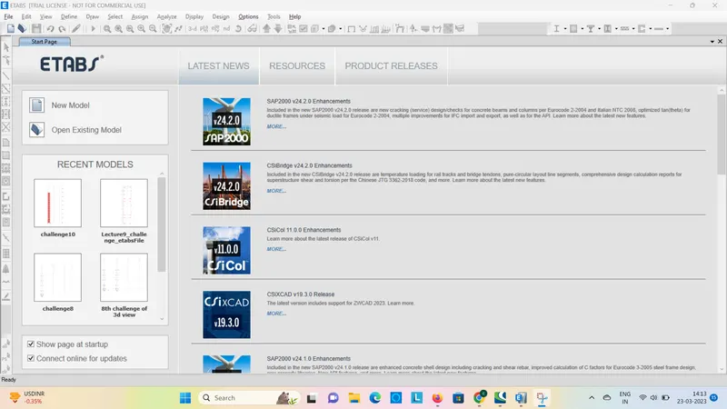
open the etabs software
set the grid and storey details using editing optionx-direction and y direction with the proper spacing
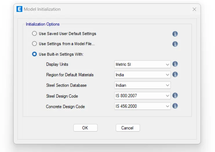
Now in the model initiation window desired units, Design codes which are to be used was
selected.
Step 2)
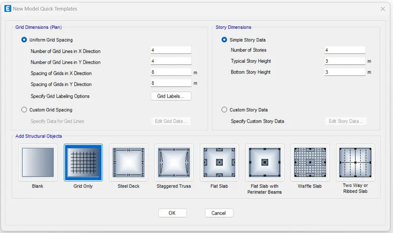
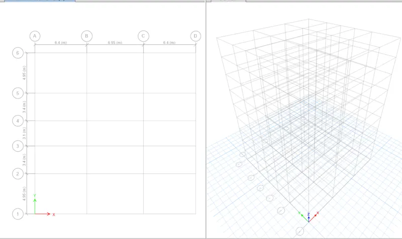
a. In New Model Quick templates under grid dimensions select the custom grid spacing
and then click edit grid data.
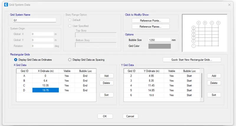
b. The grid dimensions were inserted according to CAD file drawing as follows
Step 3)
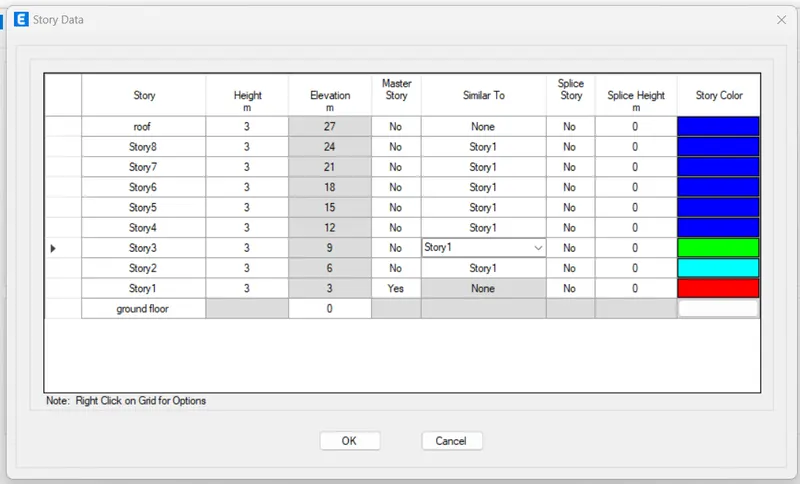
a. Now we have to enter the Story data as per cad files. (It's G+7 building)
b. Floor to floor height is given as 3m
c. For that click on New Model Quick templates under Story dimensions select the custom
story data and
d. then click edit story data.
e. Now input the storey details as given in question and story 1 was selected the master
story as and was applied to rest story from 2nd story to roof and then click OK
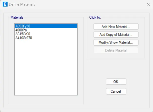
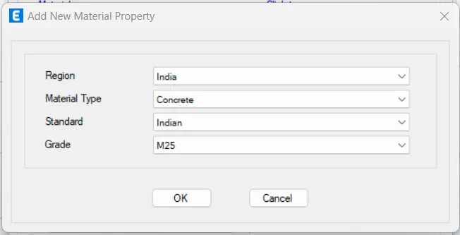
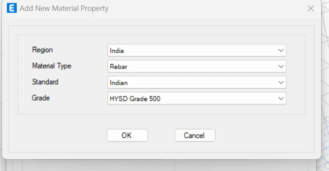
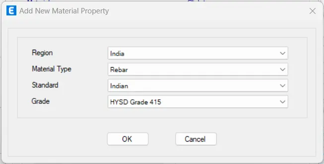
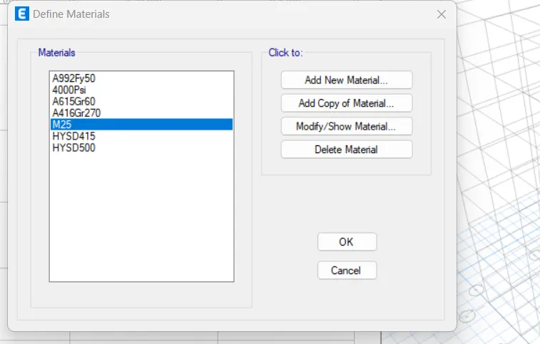
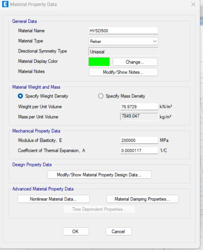
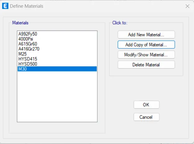
- Next we need to define the material property for concrete and reinforcement.
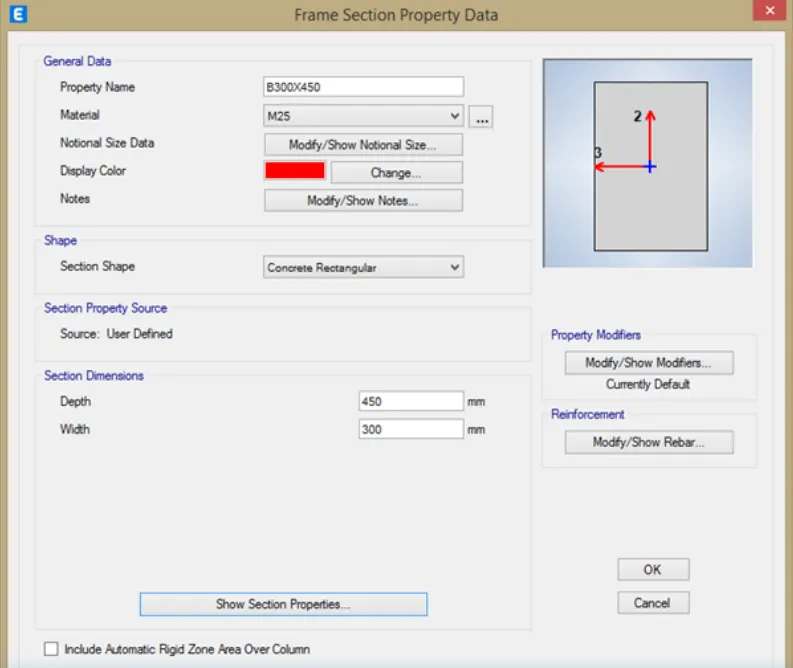
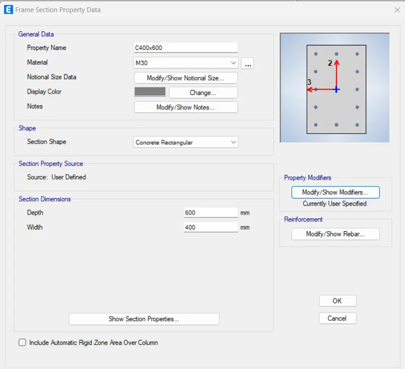
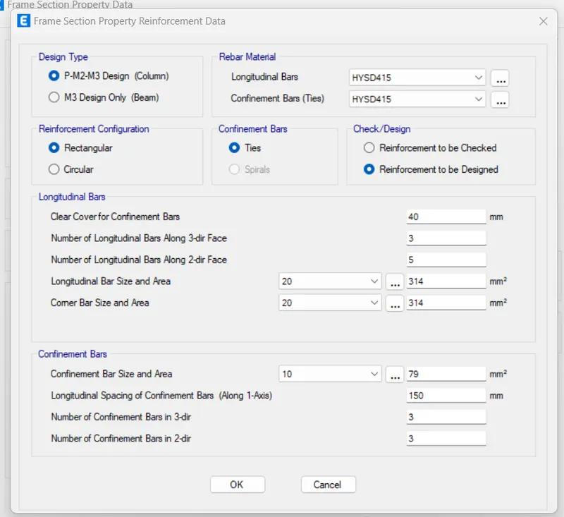
- Then, define the section property for column, beam and wall. For this, go to define tab --> section property --> frame section --> Beam 300X450mm and column 400X600mm.
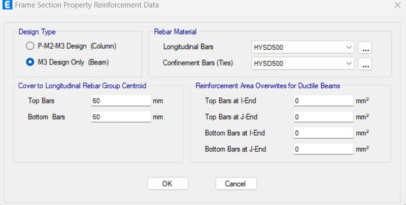
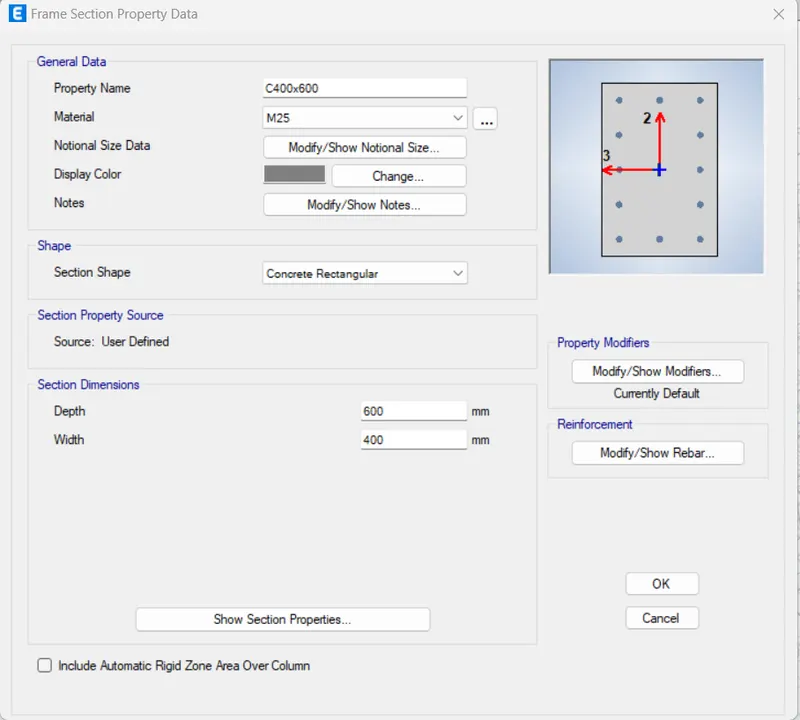
- Beam details (250x450) was provided as shown in figure and then click on Modify/ Show
reinforcement under reinforcement section 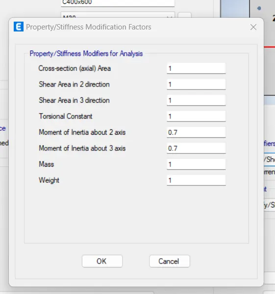
- Similarly the beam of size 300x500 is also added by following same steps
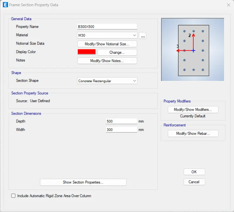
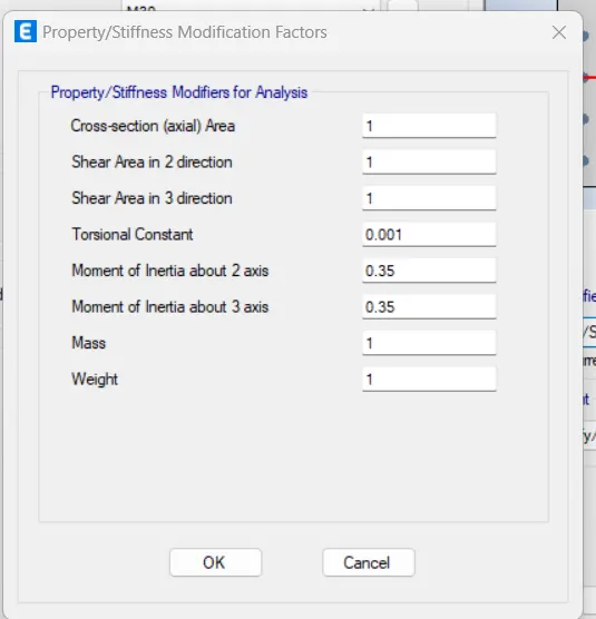
- From property list we can see the columns of size 400x400 and 400x600 and Beams of
size 250x450 and 300x500.are added 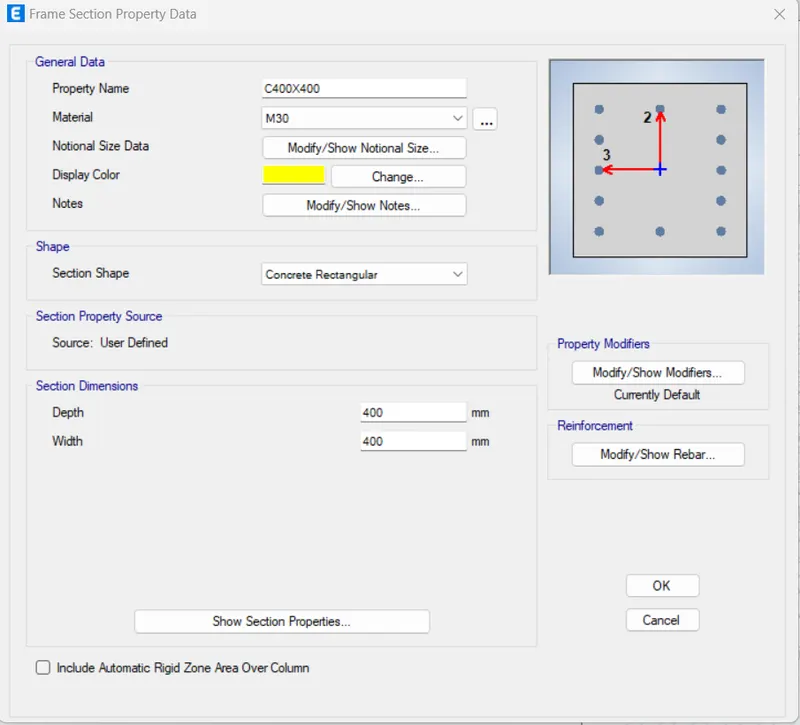
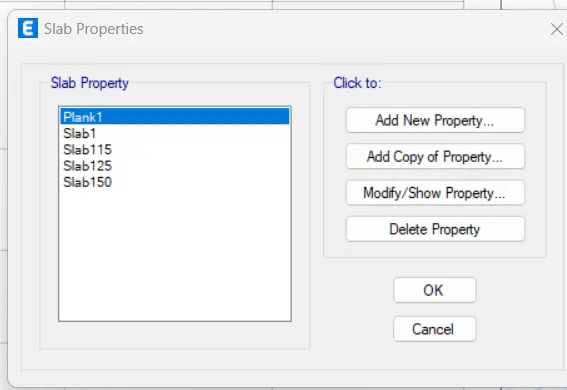
To design the slab initially for select slab section from the section properties under
define menu
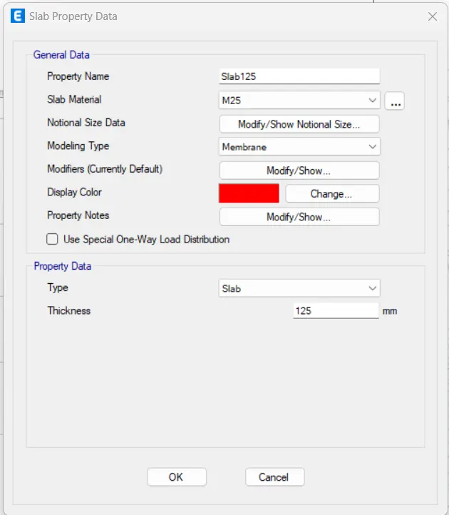
select add new property option
b. Slab properties like thickness and other details are added as shown below and then click
ok
c. Give the thickness = 125 mm
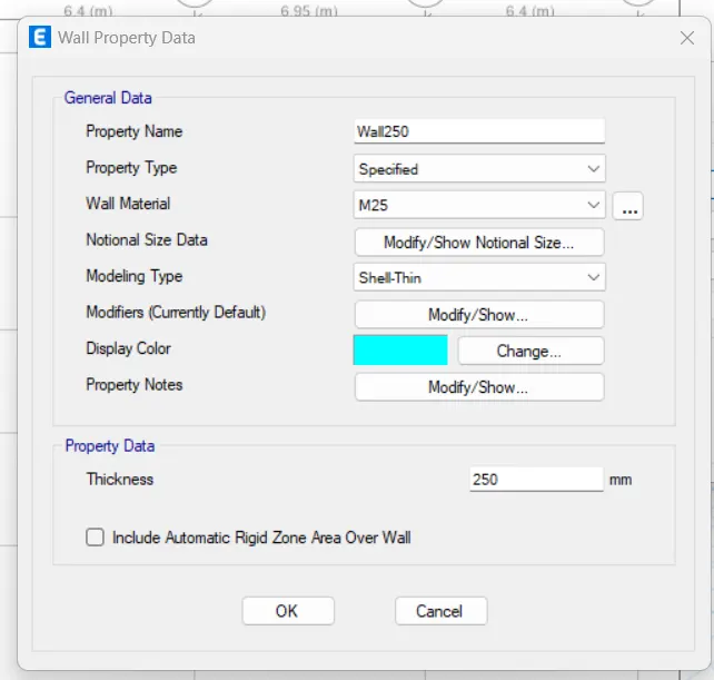
Now we have to add the shear walls
b. For that click on Define- section properties-Wall sections
c. Assign the wall thickness as 300 mm
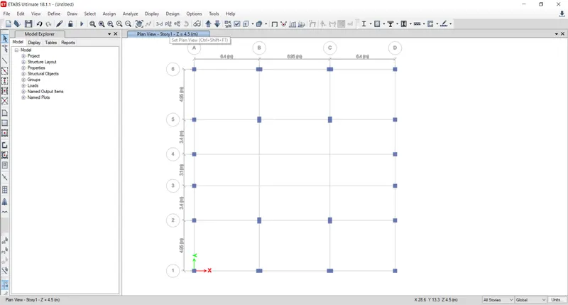
First we have to draw the columns by using quick draw column option
- So, for this go to quick draw columns and place the columns at suitable positions(C400x600).
- Similarly place the beams(B300x450) and shear walls at suitable locations without obstructing the parking area.
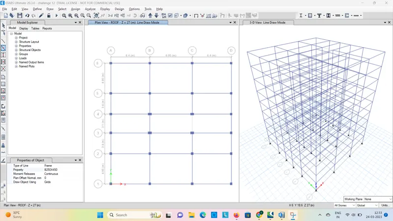
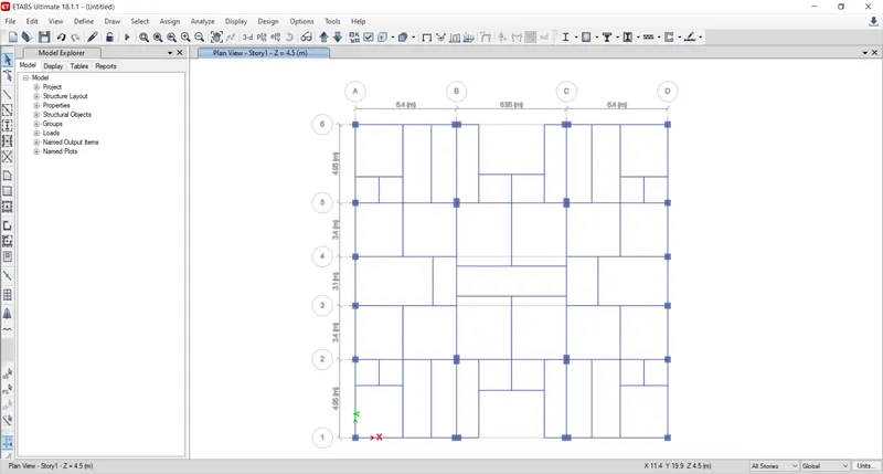
Next we need to add the beams using the Quick draw beams option, as shown below.
Next we need to add the secondary beams using the Quick draw beams option, as shown below
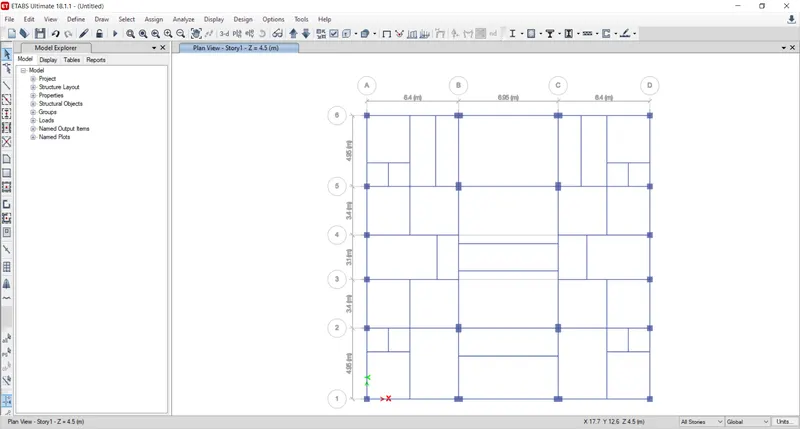
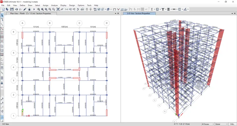
Next we add the shear walls in required locations in the residential building, as shown below.
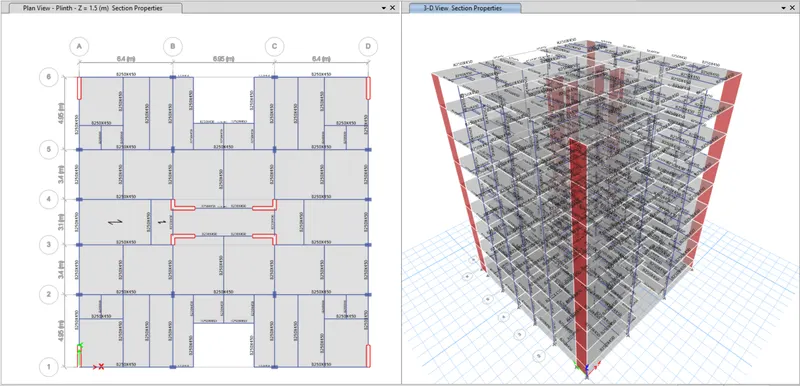
Next we need to add the slabs using the Quick draw floor/wall option, as shown below.
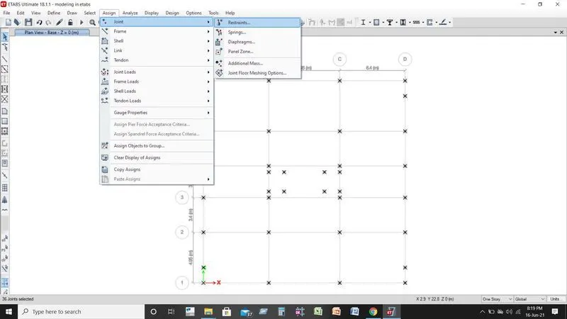
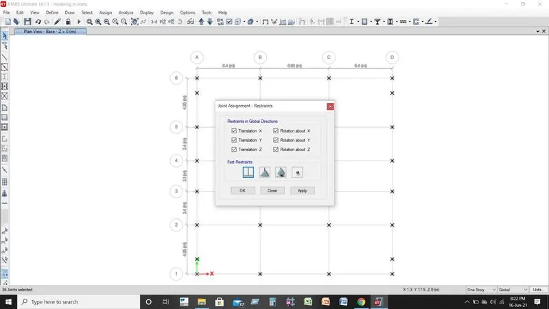
- Now we go to the base plan and select all base joints.
- Next we select the Restraints from joint option, as shown below.
- Now we need to select the fixed joint and click on apply and then click on close button, as shown below.
-
Step:-18
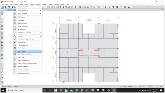
- Next we need to select the load patterns from the define option, as shown below.
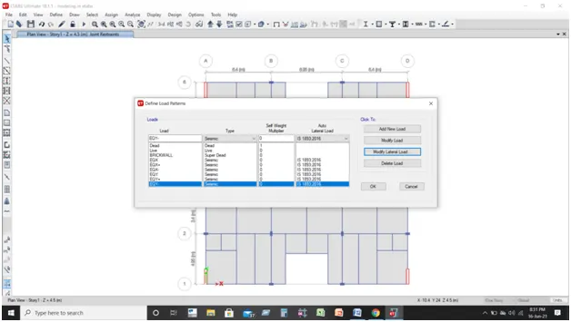
- Now we should add Dead load, live load, Brickwall load, and earthquake load, as shown below.
Step:-19
- Next we need to select the distributed load from the frame loads, as shown below.
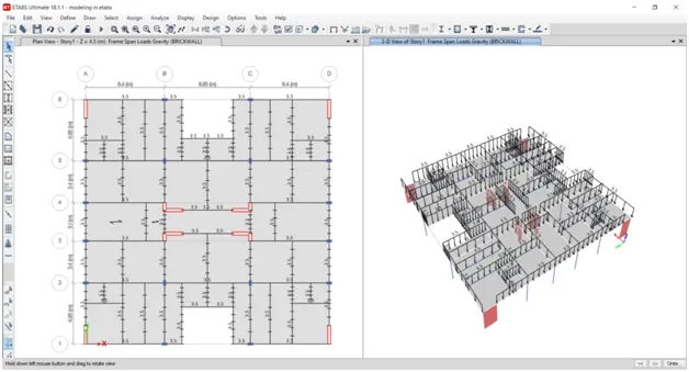
- Next we have to click on the assign option and then select shell loads, from the shell loads we select the Uniform option, as shown below.
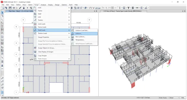
- Here we apply the 3kNm2">3kNm2live load for the staircase portion, varanda, and lift core area.
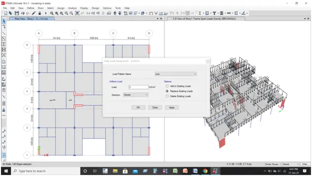
- Next we apply the 2kNm2">2kNm2
- live load for the remaining portions in the residential building, as shown below..
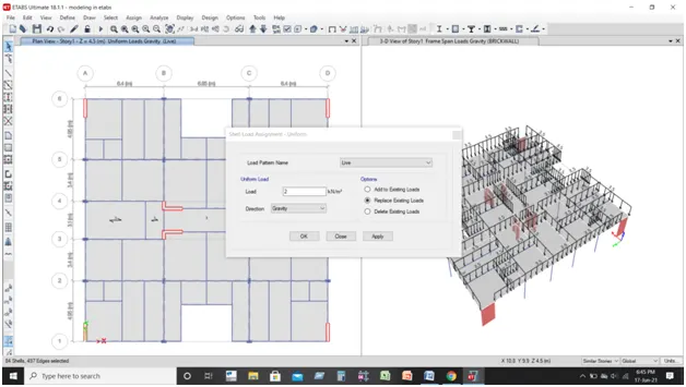
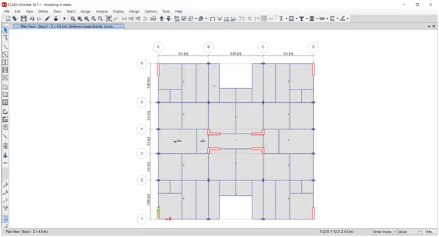
- Next we have to select live load reduction factors from the design option, as shown below.
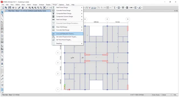
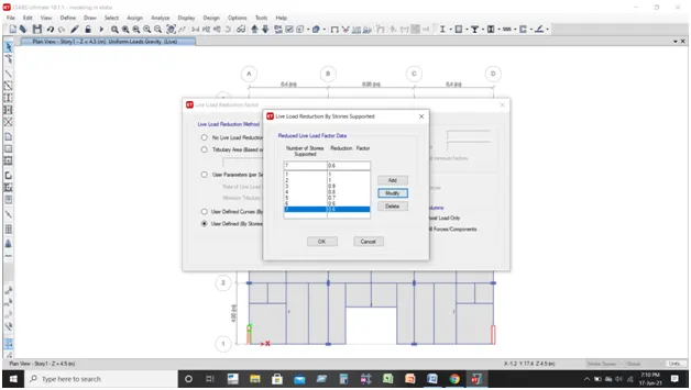
- Now we add the reduction factor by decreasing 10% from 1st floor to 7th floor, as shown below.
Step:-22
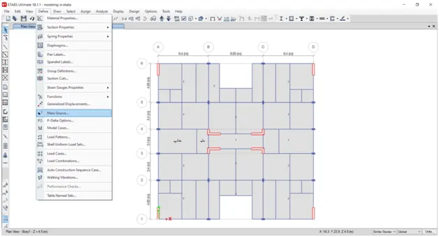
- Next, from the define option we select the mass source, as shown below.
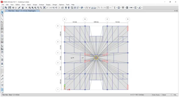
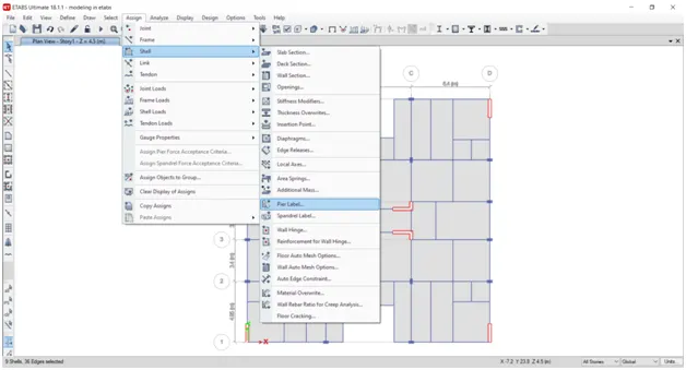
- Next we have to select the Pier label from the shell option, as shown below.
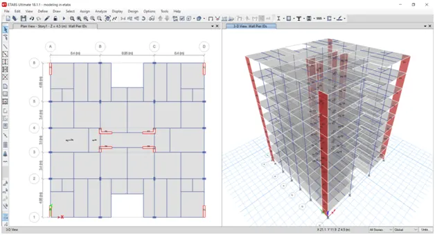
- Before going to the shear wall design we have to assign the names for the shear walls(P1,P2,P3,P4,P5,P6,P7,P8), as shown below.
Step:-25
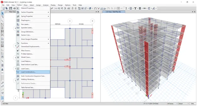
- Next, from the define option we select the load combinations, as shown below.
Step:-25
- Next, from the define option we select the load combinations, as shown below.
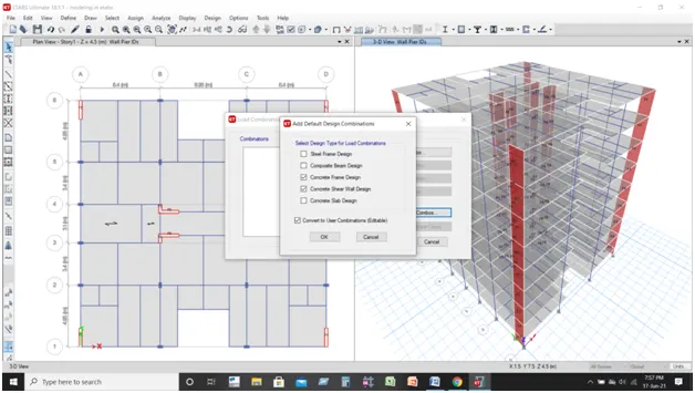
- After selecting the load combinations the new tab is visible, In that we select 'Add Default Design Combos' option.
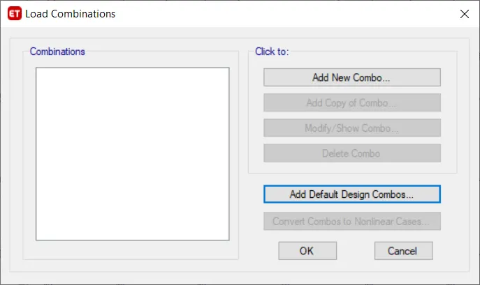
- Next we select "concrete frame design" & "concrete shear wall design" in the 'Add Default Design Combinations', as shown below.
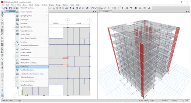
- Next we have to select the Load cases from the Define option, as shown below.
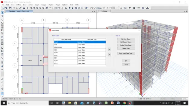
- Next the Load cases tab will be visible, In that we select the 'Add new case', as shown below.
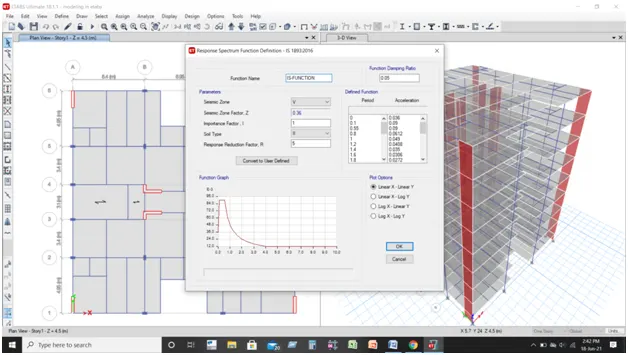
Step:-29
- Next we have to select the Load cases from the Define option, as shown below.
- Next the Load cases tab will be visible, In that we select the 'Add new case', as shown below.
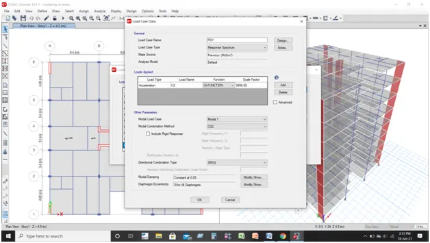
- Now we have to do the run analysis, as shown below.
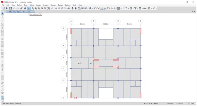
- Next, from the display option we select the show tables option, as shown below.
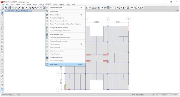
- After selecting the show tables option the new tab will be visible.
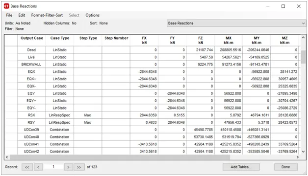
- Now we select the Base Reactions and click on the ok button, as shown below.
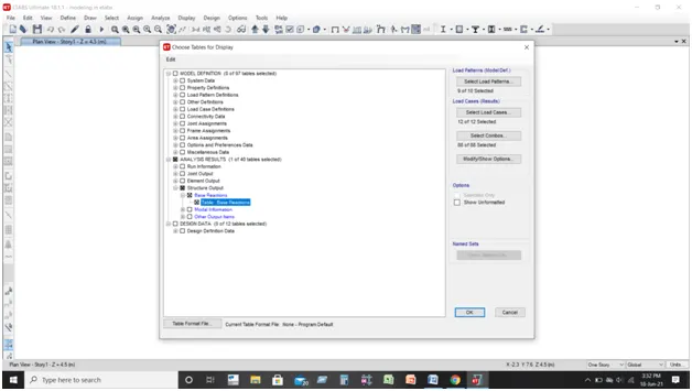
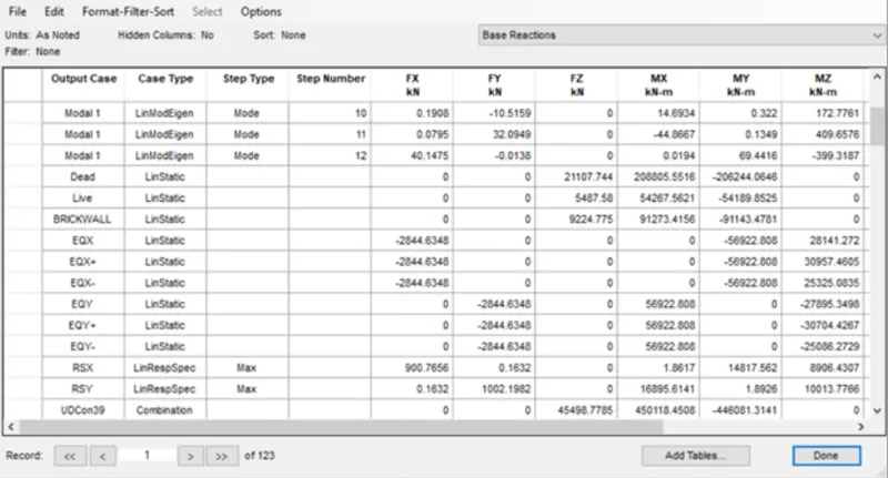
- Next the Base Reactions table will be visible, as shown below.
- Here we have to check that EQ should be closer to the RS, to get the closer to each other we should calculate that, (EQRS)×
- Scale factor of Response spectrum.
- Now substituting the values from the table, at X-direction (2844.6348900.7656)×(9806.65)
, at Y-direction (2844.63481002.1982)×9806.65
- At X-direction we get, 30969.6
- At Y-direction we get, 27835.15
- We put the above values as scale factor for response spectrum at X and Y directions in the load case data.
-
-
- Next we open the select plan view tab and select the base floor, as shown below.
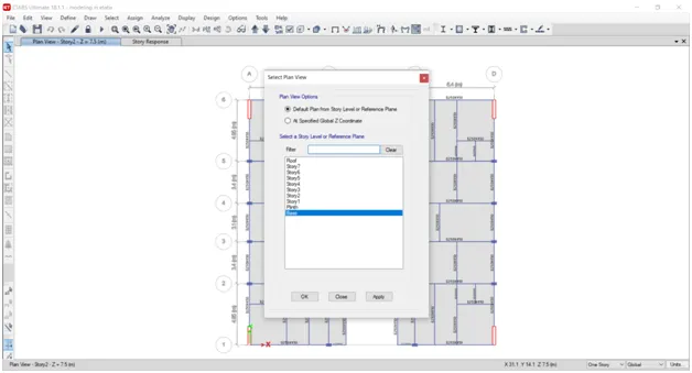
- Next we have to open the reactions tab, then we select the eartquake load towards X-direction(EQX) in the load case, then click on the ok buttion as shown below.
- Now the base shear reactions will appear, as shown below.
- When we divide the base shear taken up by the shear wall divided by the total base shear of building will get the % of the shear forces taken up by the shear wall.
- And if that is less than 80%, then the more shear walls we need to add to the structure.
-
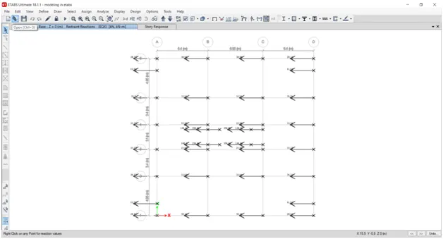
- Now the base shear reactions will appear, as shown below.
- When we divide the base shear taken up by the shear wall divided by the total base shear of building will get the % of the shear forces taken up by the shear wall.
- And if that is less than 80%, then the more shear walls we need to add to the structure.
- Now the base shear reactions will appear, as shown below.
- When we divide the base shear taken up by the shear wall divided by the total base shear of building will get the % of the shear forces taken up by the shear wall.
- And if that is less than 80%, then the more shear walls we need to add to the structure.
result The G+7 residential building has been modelled and analyzed successfully using the ETABS 2018