Structural Modelling using Etabs 2018
The architectural drawings for a G+7 residential building in zone 5 has been provided. The floor plan is the same for all 7 floor levels. Possible column positions have also been provided. Conceptualize a framing plan layout and then model the building in Etabs. The following architectural drawings have been provided:
- Typical floor plan – The location and thickness of the brick walls and the use of the
space (for estimating live load) can be obtained from this plan - A building section through the staircase and lift core is provided
- Parking layout in the ground floor – the column/shear wall arrangement must not
obstruct entry/exit of vehicles.
The following loadings are to be taken into account: - Brickwall made of AAC blocks
- Finishes – floor tiles of 75 mm thickness
- Live loads as per IS 875 part 2
- Water tank of 20 KL above the staircase at Mumty level
- Lift Machine room at mumty level above lift core
AIM
To model and analyze the G+7 Residential building at given architectural drawings by using Etabs Software.
PROCEDURE
STEP-1
- Open the new model in Etabs.
- Then open a another Tab of Given G+7 building model as included a floor plan, architectural plan, Typical cross sectional plan and elevation plan.
- To analyze and observe the data from given model.
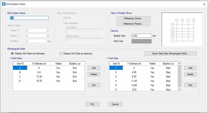
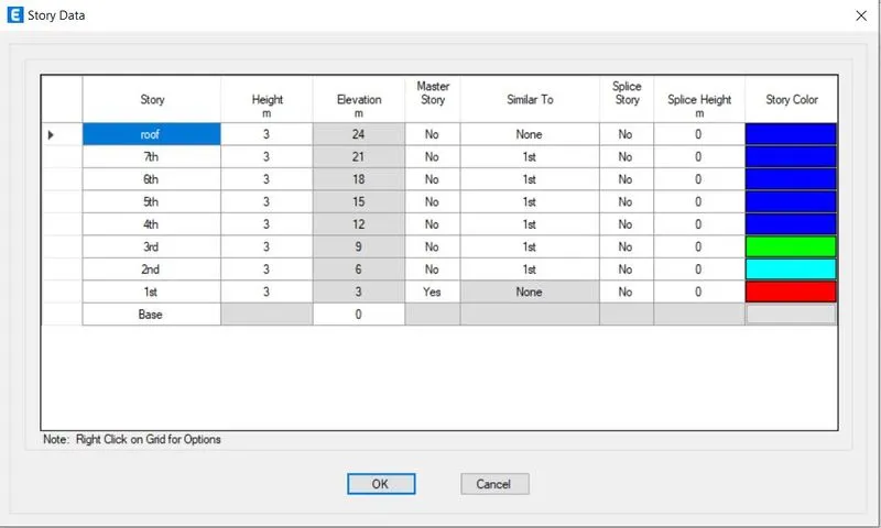
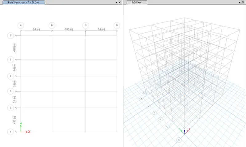
- To set the Grid and story formation by custom.
- X-direction in A,B,C &D and Y-direction in 1,2,3,4&5 at given base dimension.
- The story are designed by G+7, each floor have 3 m in height.
STEP-2
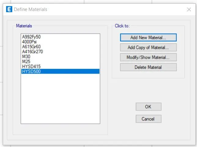
- To add Material properties of section for steel and concrete
- Go to Define > Material properties > ADD.
STEP-3
- To add the section properties of Beam, column and slab.
- Go to section properties > frame > choose bram or column
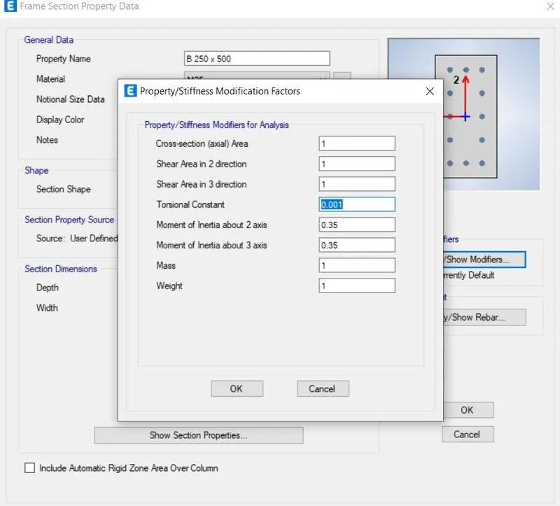
- Here used beam size is B 250 mm x 500mm
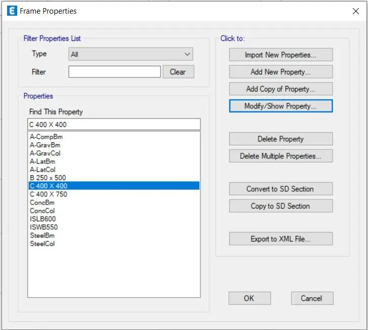
- The column Size is C 400mm x 400mm, C 400 x 600.
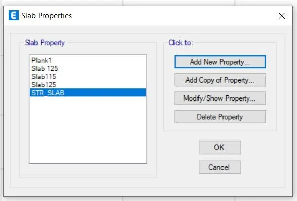
- To create slab section of Slab 115, slab 125, slab 150mm thickness.
- Specially we add staircase slab of 200mm thickness.
STEP-4
- To create a shear wall of this structure to protect the more lateral forces Zone.
- Wall > section properties > wall section.
- For here used, wall 300 thick.
- The shear wall are covered as symmetric in nature for withstand the lateral shear force action.
STEP-5
- After completing the addition of all materials of required in modeling.
- Then we start to view the floor plan.
- To select the Quick Column for selecting the required dimension.
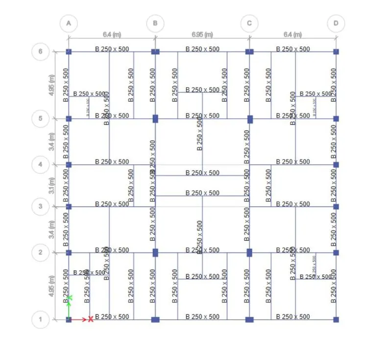
- Then, similarly to add the process of beam.
- For most concentration about to adding the beam, because we read the given plan and understand the appropriate requirement of place to add beam.
- If we want to delete or adding new beam inside the frame area.
- Choose To Divide and Joint action for fixing the beam layout like our given plan.
STEP-6
- Next, we add the slab @ thickness of slab 115.
- Go to First floor, select all Stories after to add slab.
- Then, go to base floor deleted the slab @ base.
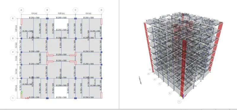
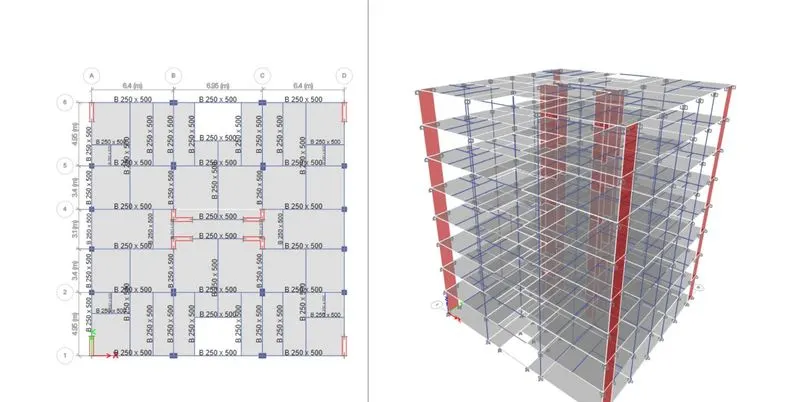
STEP-7
- To add the Shear wall of all Boundary condition and base point and mid portion of building as like a symmetric in nature.
- Thickness of shear wall is 300mm.
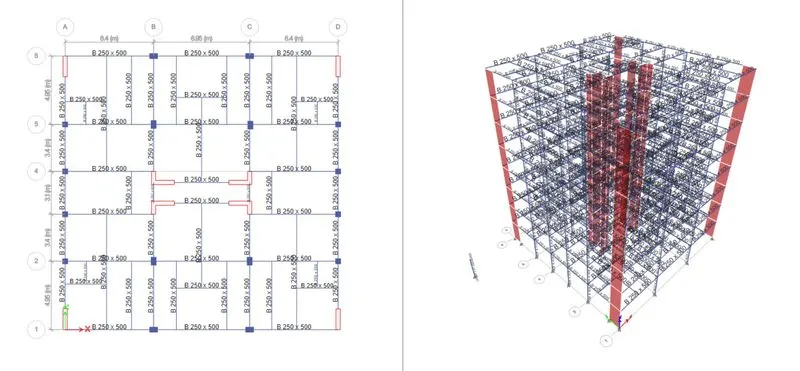
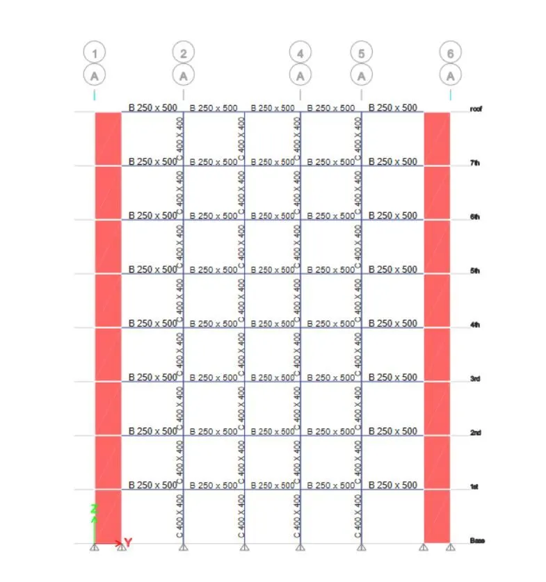
STEP-8
- Go to base plan and select one strory.
- After select the all joints.
- ASSIGN > Joints > Restraints > Fixed joints.
STEP-9
- Then, most important factors of addition of load .
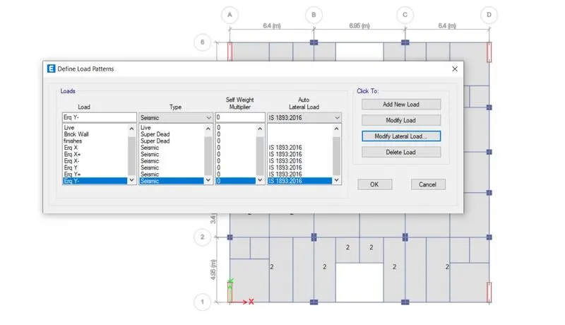
- Define > load patterns > add the load 0f Dead, Live, Brickwall and Finishes.
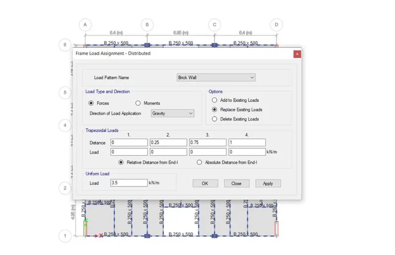
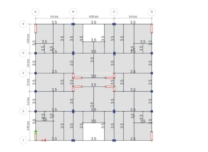
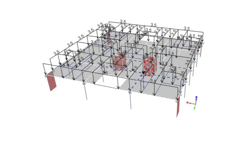
- Addition of brick wall load > Assign > Frame load > Distributed load > brick wall is 3.5 KN/m.
- As the reference IS 1893 : 2016.
STEP-10
- Then addition of Live @ different categories with the reference of IS 875 :PART 2.
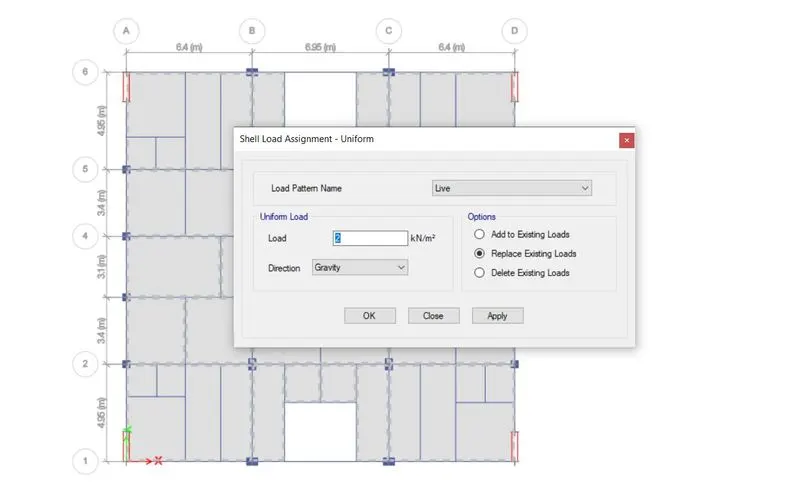
- Here assigned live of moving platform area is 3 KN/ m^2 and other room areas we put 2 KN/m^2.
STEP-11
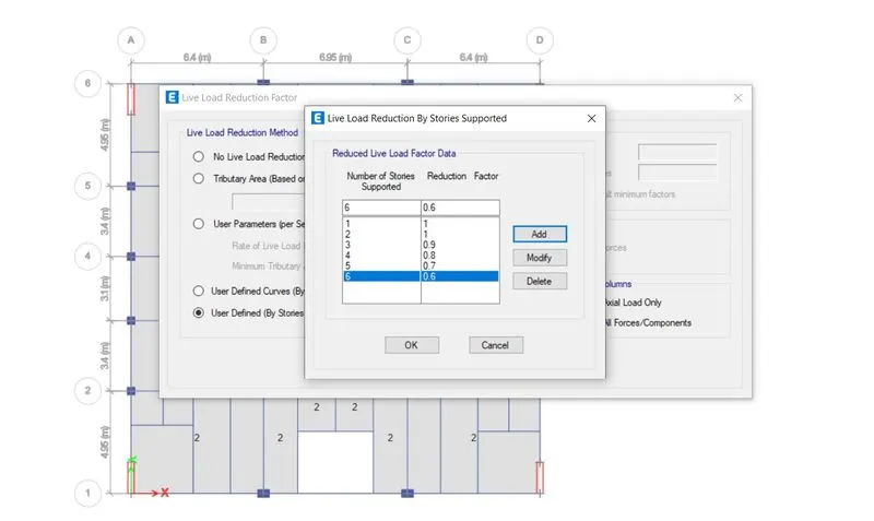
- To assist the Live load Reduction factor.
- For this model is G+7, so definitely we need to consider the reduction factor.
STEP-12
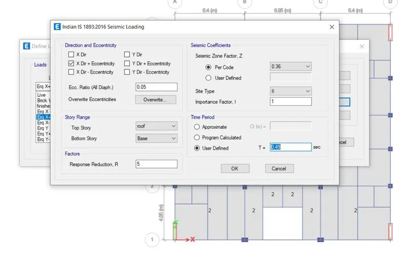
- Then, to add the earthquake load.
- We need to natural period Ts = 0.49, as we find this from IS 1893:2016.
- Next, add the Earthquake load of positive and negative of both direction.
STEP-13
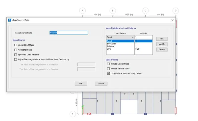
- To assign the Mass source with the condition of Specified load patterns
- To reference of IS 1893:2016, Clause 7.3.1
STEP-14
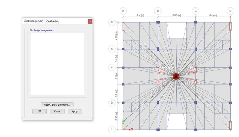
- The same we assign the Diaphragm of all stories.
- Assign > shell > Diaphragm > D1 > apply.
STEP-15
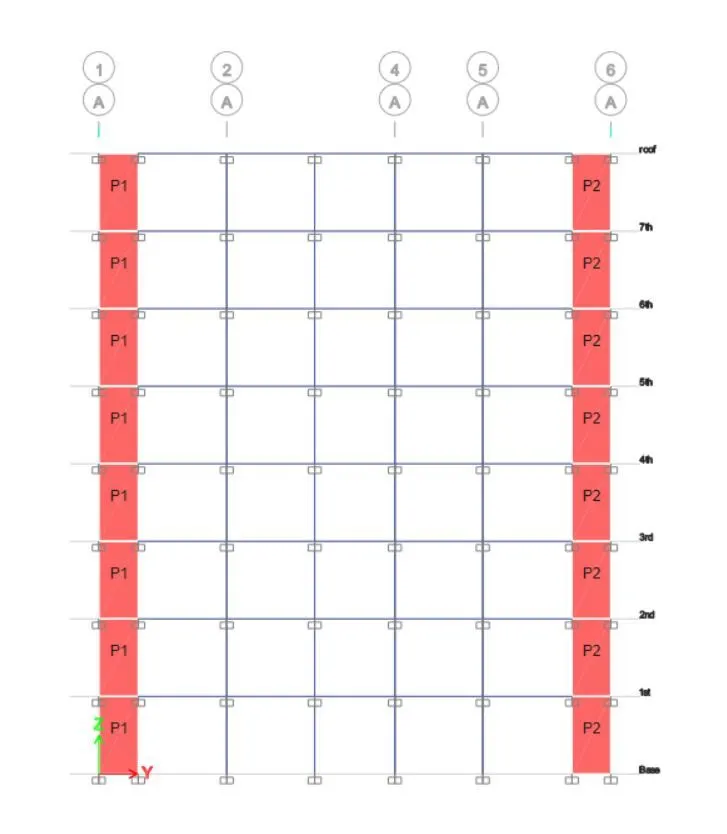
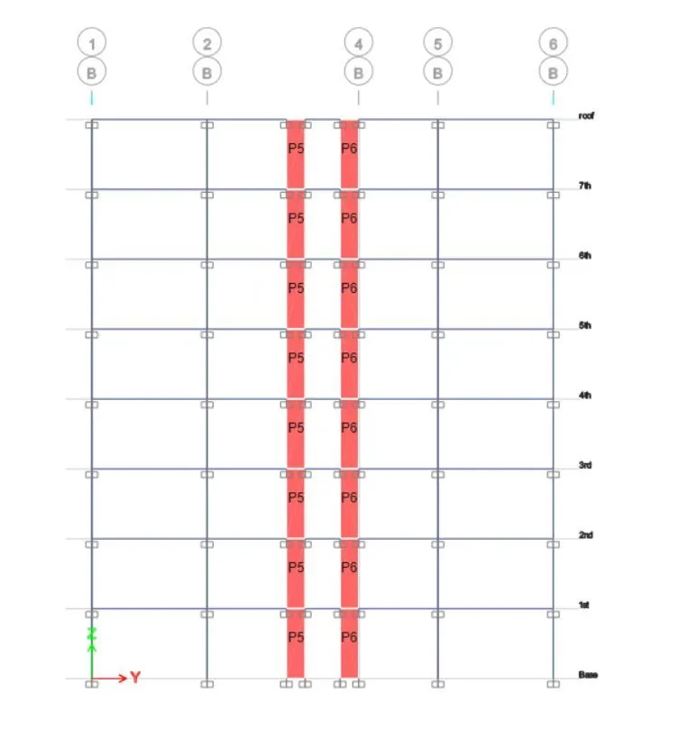
- Given the name to all pier of shear wall as like p1, p2, p3, p4, p5, p6, p7 & p8
- Assign > shell > pier label @ selected wall.
STEP-16
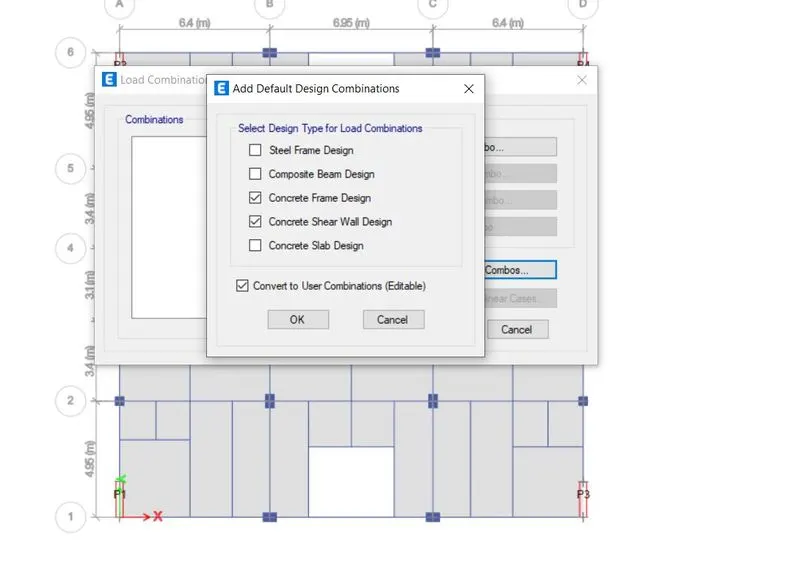
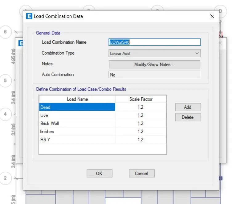
- To check and consideration of LOAD Combination @ all factors.
STEP-17
- Model cases to finf the direction of different mode shapes.
- Here we choosen 20 mode shapes.
STEP-18
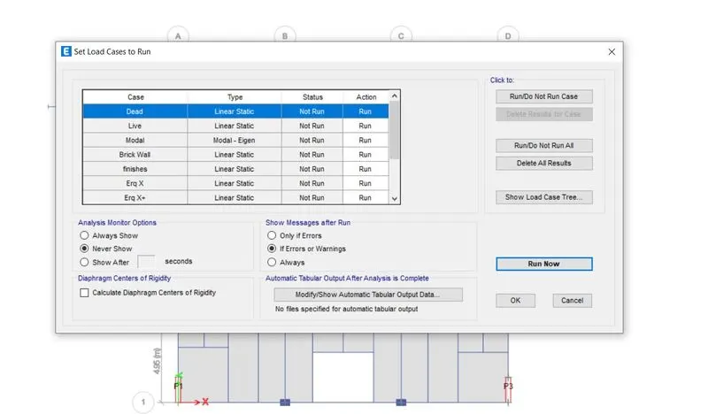
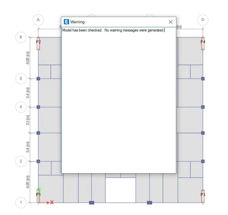
- Then , to check the analysis of all load cases.
- RUN the analysis of model.
STEP-17
- To view the Model spectrum analysis.
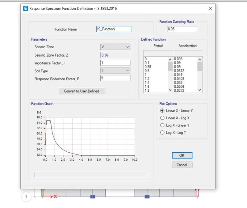
- Define > Function > add the respected factors.
- Choose function type > add new function with the reference of 1893:2016.
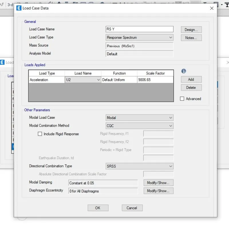
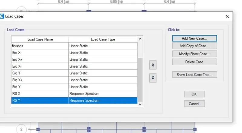
- Then, to choose Load cases for adding all load cases into the both direction of response reduction factor.
- RSx and RSy.
- After adding this load, make the load combination as similarly we add this response spectrum load and check it.
STEP-18
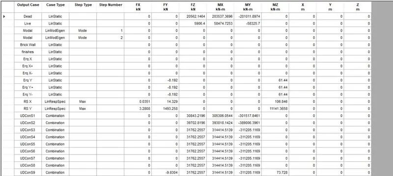
- As well as we get the base shear value @ all loads, on there we need to know the spectrum value for we considering the scale factor value.
- Then, Re-run the analysis, to check the all base shear, combination, model shapes.
- And also we get the view Story drift of maximum value as our model.
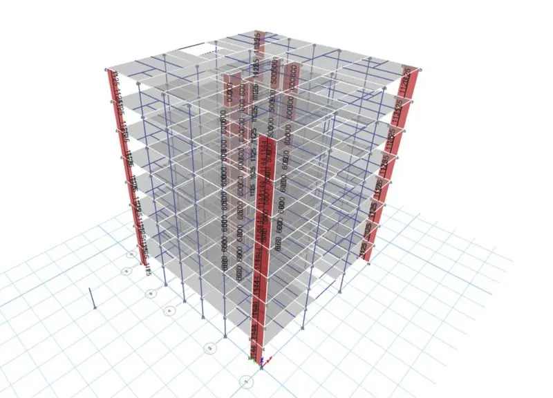
RESULTS
Finally, we analyze the model of G+7 are successful.