Structural Modelling using Etabs 2018
CHALLENGE 09
Aim:
To model and analyze the G+7 storey building using ETABS with application of proper load cases and load combinations for the given typical floor plan drawing.
PROCEDURE:
- Initially open the given architectural plan in Auto cad and study the plan & locate the postions of beams, column and shear walls.
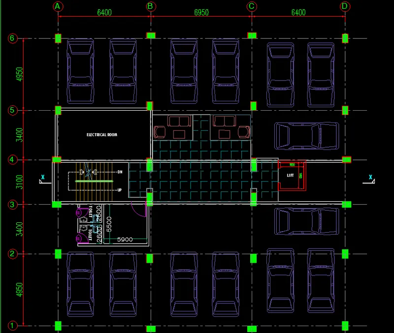
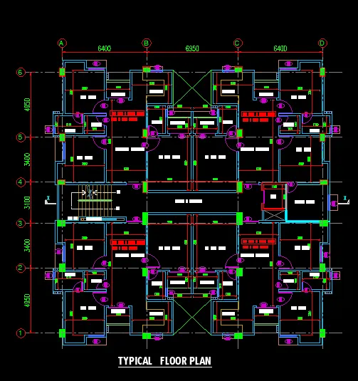

- After done the postioning then the strctural plan should implemented in the Etabs software.
Step 1:
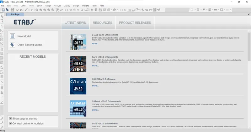
Open the ETABS Software.
- so, now open the etabs software and click on the new model option.
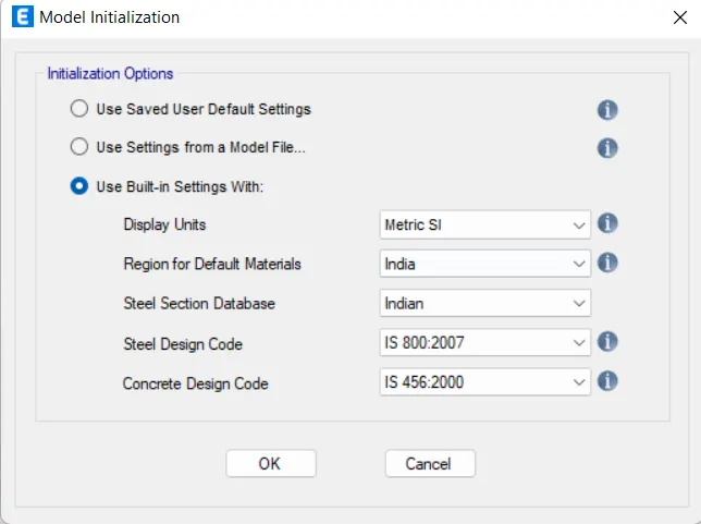
- It will appears a model initialization window, then select the Use Built-in settings with option and fill the units and codes as per the detailes we used.
- Then again it will appear another window-New model quick template. By using this tempate select the grids and storeys and respectivelty it dimensions also.
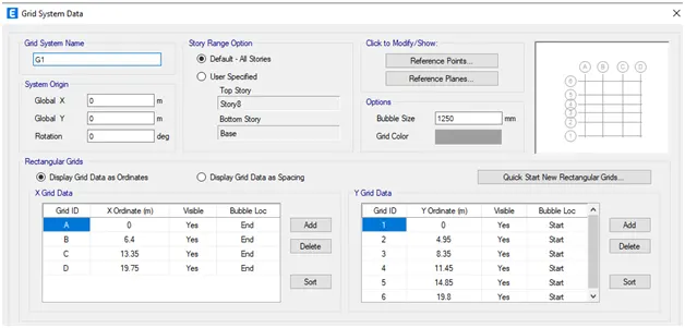
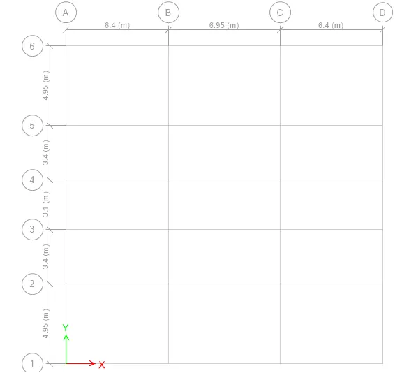
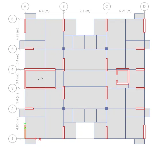
Set the Grid and storey details using editing options.Provide 4 grids at x-Direction and 6 grid at y-Direction with the proper spacing.
Step 2:
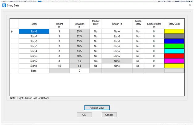
Now define each story and story height.
Step 3:
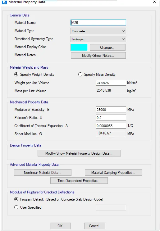
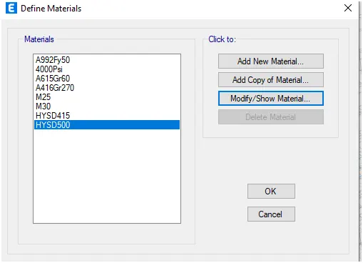
Click Define tab and select the materials.Choose the material type such as concrete for M25.
Step 4:
Similarly for Rebar material, Click define select add new material option and choose the type as Rebar.
Select Grade as HYSD grade 500.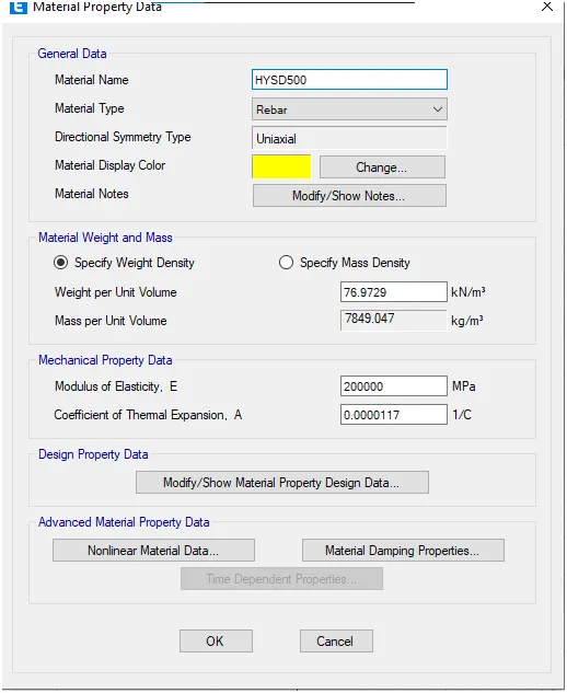
Step 5:
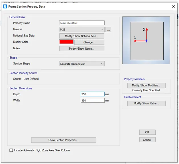
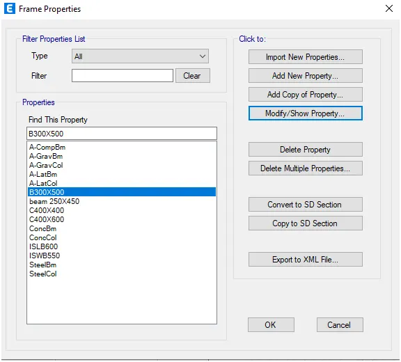
Click define tab.Select frame section property
Provide the beam dimensions as 350 x 550.Then modify the rebar details.
Step 6:
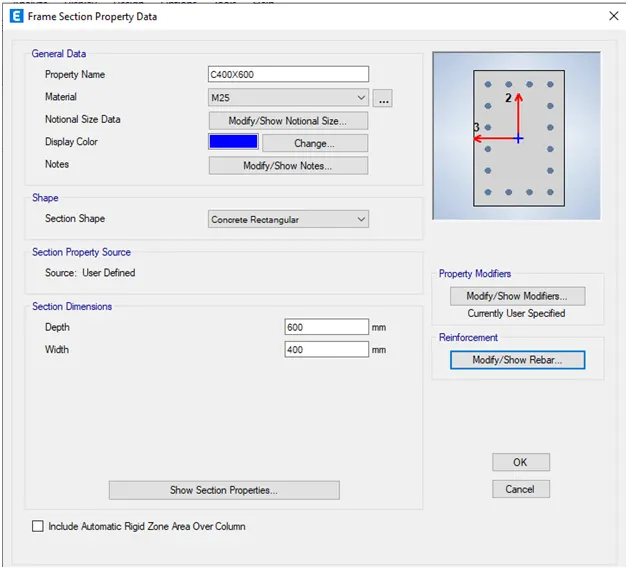
Click define tab.Select frame section property
Provide the Column dimensions as 400 X 600.Then modify the rebar details.
Step 7:
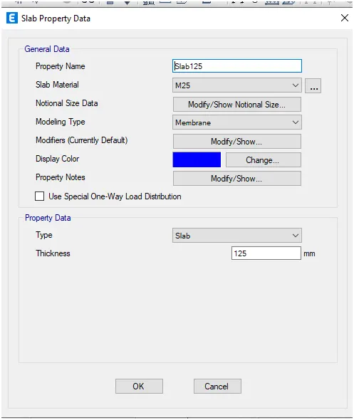
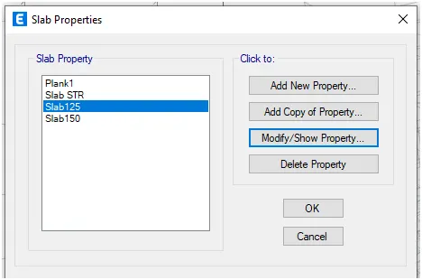
Click define.Select Section properties.Click on slab sections.
Provide the thickness of the frame as 150mm.
Step 8:
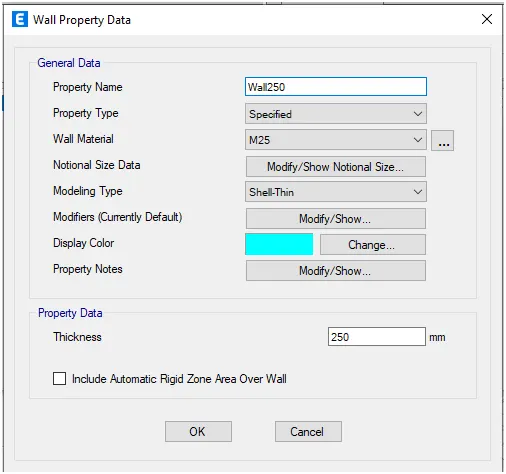
Click define.Select Section properties.Click on Wall sections.
Set the thickness of the wall as 250mm.
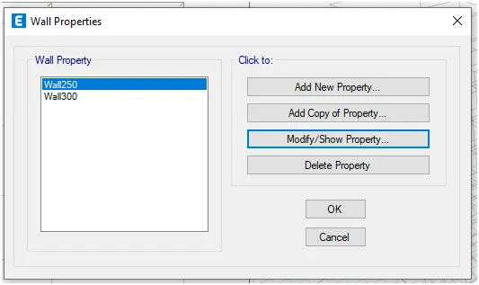
Step 9:
By using the Quick draw column/beam option place the columns in the floor plan at each grid intersection.
Select all storey option.
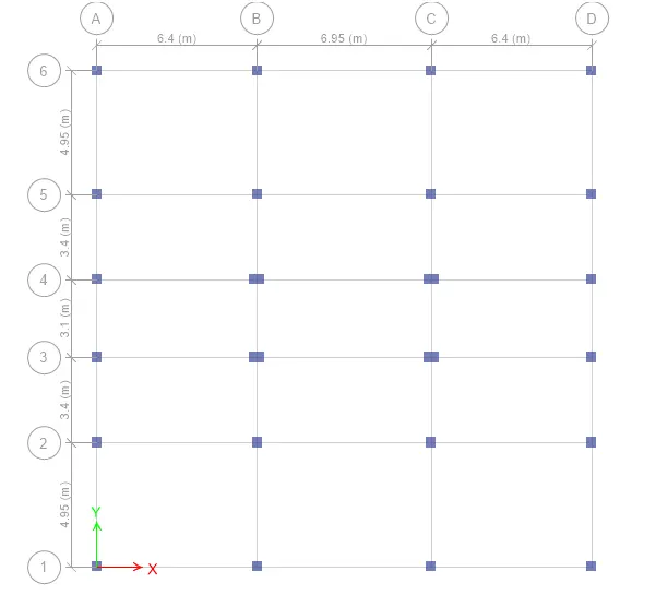
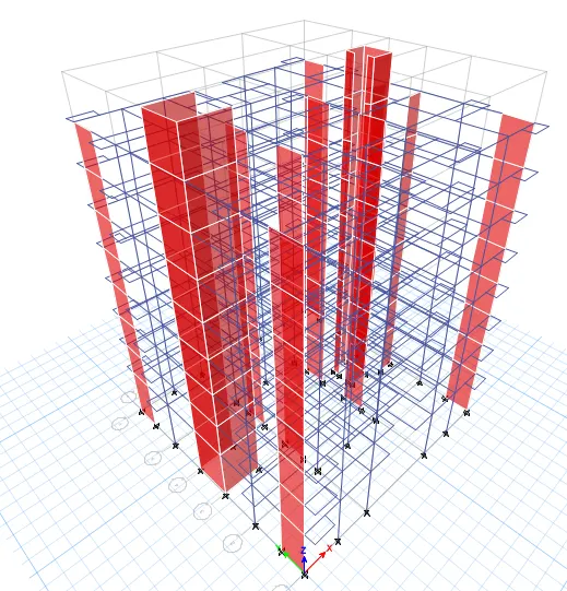
Step 10:
Similarly draw the beams as per the floor plan.
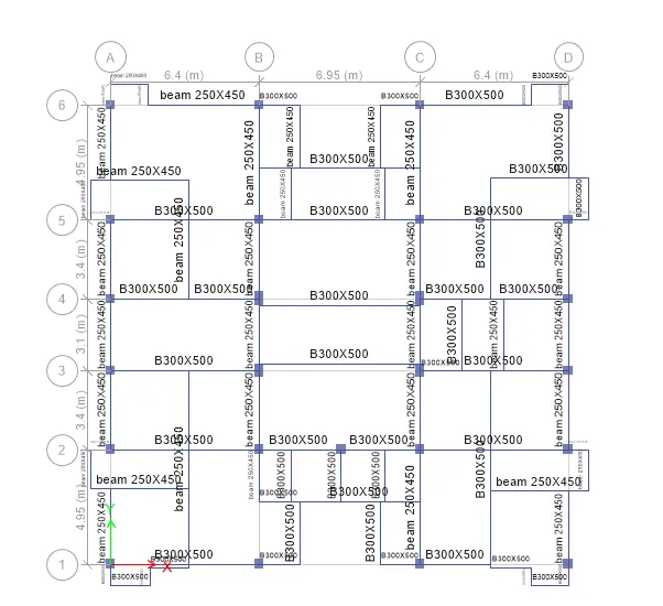
Draw the shear walls in required places.
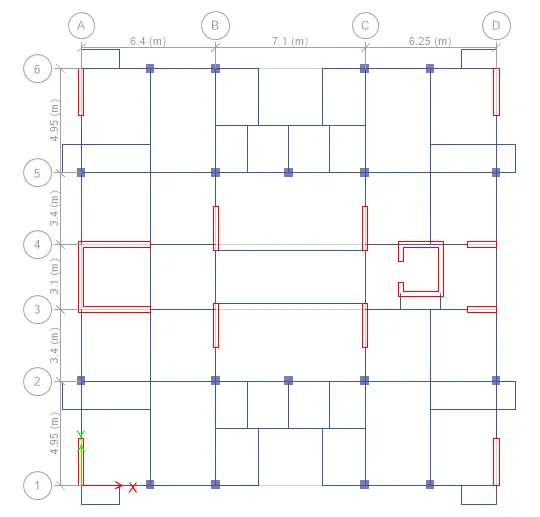
Step 11:
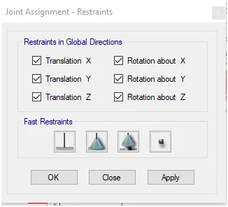
Click on the plan and select base.Select one story.
Slect all the column base.
Click on assign .Select joint.Select the joints as fixed.
Step 12:
By using the Quick draw floor/draw rectangular floor plan option place the floors.
Select all storey option in bottom tool bar.
Step 13:
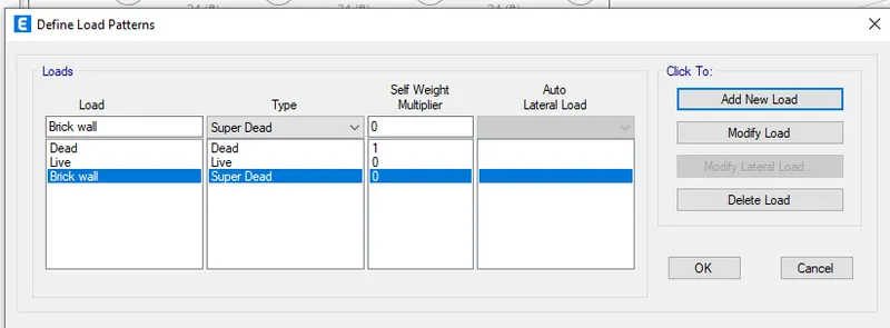
Click on the load patterns and define dead,brick wall and live load.
Step 14:
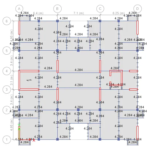
Apply the brick wall load in all the beam component.
Step 15:
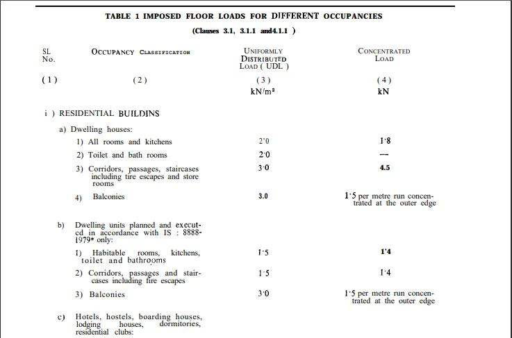
Apply live load as per IS 875.
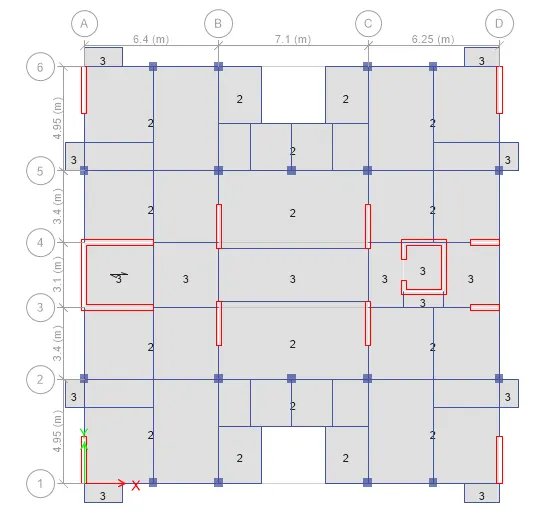
Live load = 2kn/sq.m ( As per table 1 from IS 875 Part 2)
Live load = 3kn/sq.m for balconies ,lift area and walk -way ( As per table 1 from IS 875 Part 2)
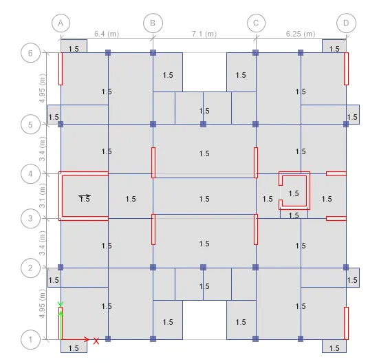
At the roof we take only 50% of live load.
Step 16:
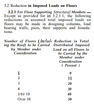
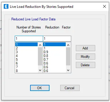
Similarly the reduction factor has been taken from clause 3.2.1 in IS 875 part 2
Step 17:
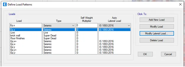
Click on the load patterns and define the sesimic loads.
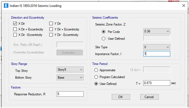
Calculate the time period T value from IS 13920 clause no 7.6.2
Step 17:
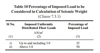
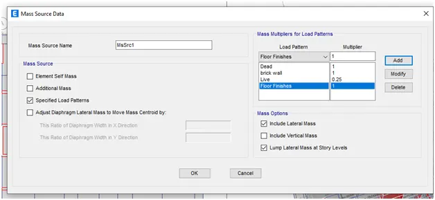
Define mass source.
Step 18:
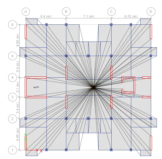
Select on all story option.Goto select -Objective type-Floors.Select all the floors.
Goto assign ,click on shell ,click on diaphragms.Assign the dia-phragms to all the floors.
Step 19:
Go to Define .Click on the pier labels and the pier labels.
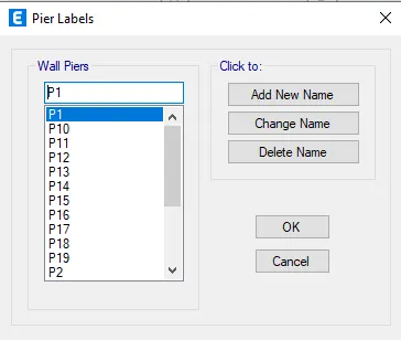
Select the shear walls one by one and assign the pier labels.
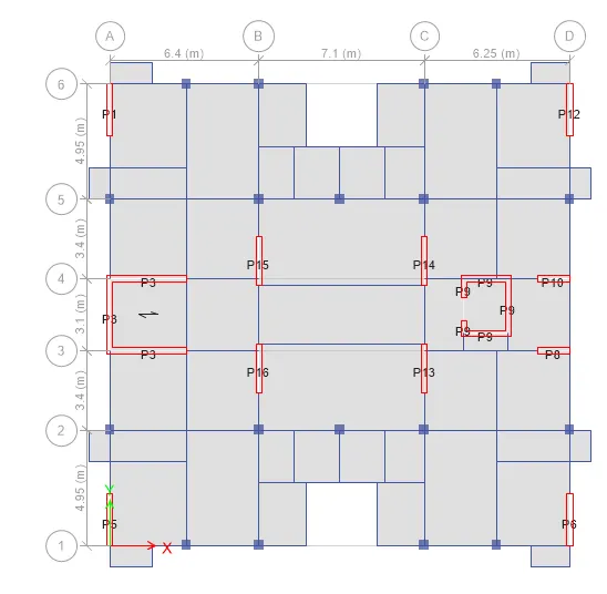
Step 20:
Click on the load cases and define the no.of modes.
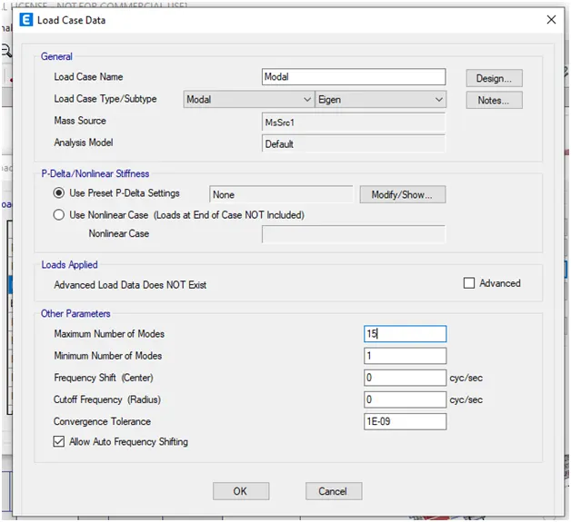
Step 21:
Click on the analyze, then click on the load cases to run.Tick mark the calculate Diaphragms centres of Rigidity.
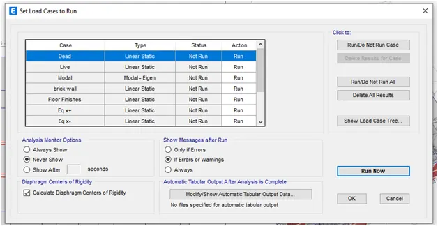
Step 22:
Click on define ,select function and select on Response spectrum.
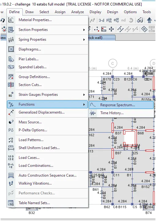
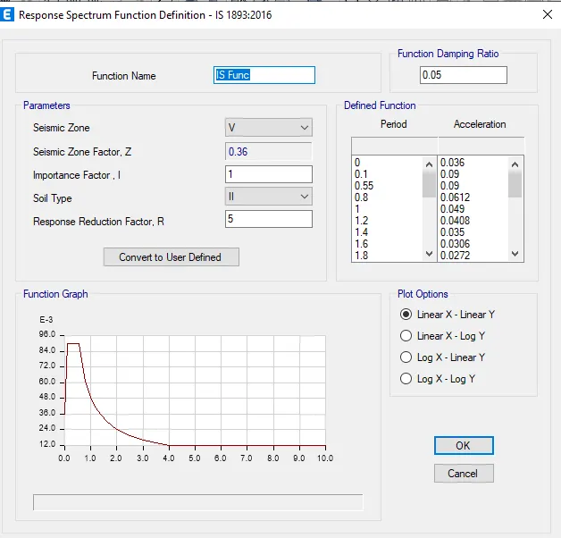
Define the response spectrum in both X and Y direction.
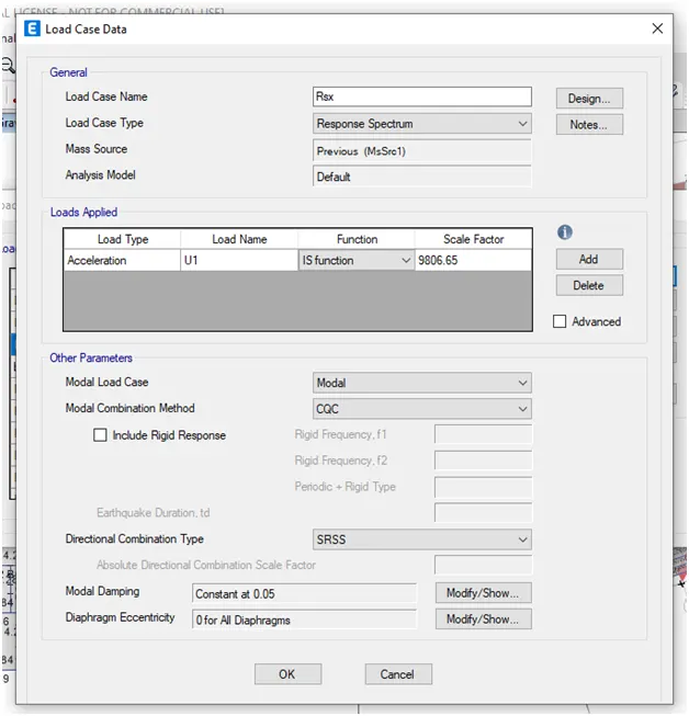
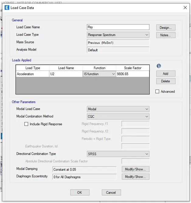
Step 23:
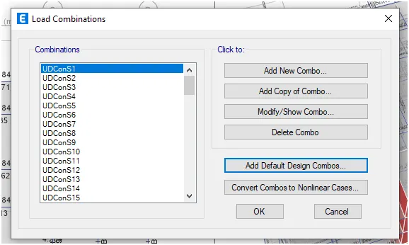
Select load combinations ,click on the default design combinations.
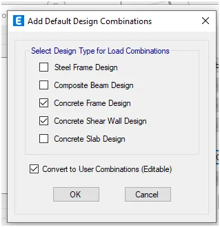
Step 24:
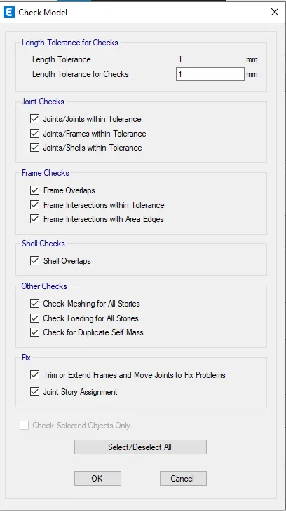
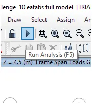
Select analyze and Click on check the model.After the Model checking Click on the Run the analysis.
MODAL PARTICIPATION RATIO CHECK
- After the completion of analaysis.Then Go to the display-show tables- analysis results-strctural ouitput-modal information - modal mass participating ratio.
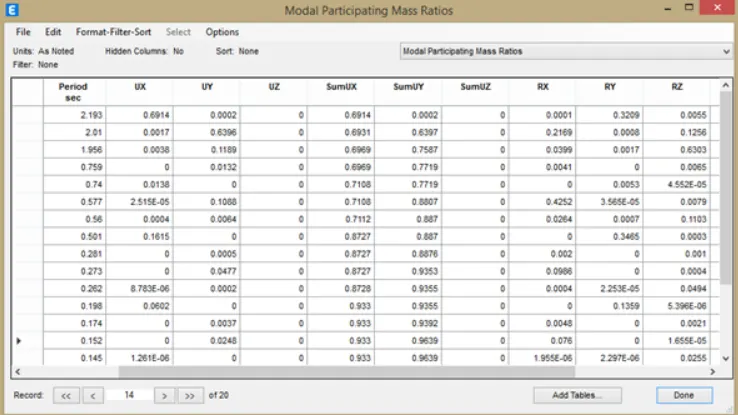
- hence stasisfied the modal participation of translational mode- first two fundamental modes should be greater than the transional mode(third one).
- mode1-0.6914
- mode2-0.6396
- mode3-0.6303
BASE SHEAR CHECK AND SCALING.
- Now, go to the base reactions.Go to the display-show tables-analysis result-strcture output-base reactions.
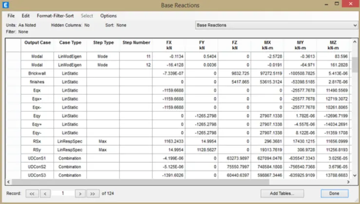
- `EQ_x= 1159.66kn & RS_x=1163.24`hence the scale factor is`1159.66/1163.24=0.996`
- `EQ_y=1265.75kn & RS_y=1128.56kn`hence the scale factor is `1265.27/1128.56=1.12`
CHECK FOR INTER-STORY DRIFT
- IN x direction:
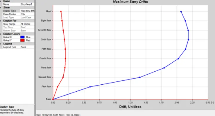
As per the codal provision os IS 1893: 2016 it doesnot exceed the 0.004
we obtained 0.0022. so henece safe. - In y direction:
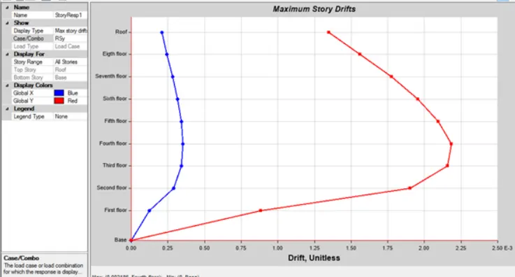
as per the codal provision os IS 1893: 2016 it doesnot exceed the 0.004
we obtained 0.0023. so henece safe.
RESULT:
The structural model must completed with provisions of IS 1893 and IS 13920.
Run a modal response spectrum analysis and checked the analysis results of the etabs model for
- inter-storey drift requirements
- vertical & planar irregularities
- minimum shear wall requirements
- maximum axial load ratio for column and shear walls
- effective moment of inertia for beams and columns etc.
REPORT:
| CHECKS | DESCRIPTION | REQUIREMENT | PROVIDED |
| 1.Modal mass participation ratio | First three modes dominates at least 65% | X-direction 0.6914+0.0017+0.0038 =0.76=76% |
Achieved |
| y-direction 0.6396+0.1189+0.0132 =0.77=77% |
Achived | ||
| 2.Modal mass participation ratio | Mode1 and mode 1 are differ by at least 10% | mode1-0.6914 mode2-0.6396 |
Achived |
| 3.modal mass participation ratio | Principle modes are greater than the transilational mode |
mode1-0.6914 |
Achived |
| 4.Base shear check | for x-direction |
`EQ_x= 1159.66kn & RS_x=1163.24` |
Hence OK |
| for y-direction |
`EQ_y=1265.75kn & RS_y=1128.56kn` |
Hence OK | |
| 5.Inter storey drift check | as per the codal provision os IS 1893: 2016 it doesnot exceed the 0.004 | X-direction=0.0022 | Achived |
| y-direction=0.0023 | Achived |