Creating a Floor plan, Footing detail and Isometric view using AutoCad
CHALLENGE 02
CREATING A FLOOR PLAN, FOOTING DETAIL AND ISOMETRIC VIEW USING AUTOCAD
1) C/S OF LOAD BEARING WALL WITH SPREAD FOOTING:
Aim:
To draw the C/S of load bearing wall with spread footing.
Commands Used:
- Rectangle
- Line
- Trim
Procedure:
Step-1: Create Rectangle by using REC command.
- Specify the first corner point as (5,5)
- Specify the length of rectangle =0.9 units in command box
- Specify width of rectangle =0.25 units in command box
- Then create another REC command
- Specify the first corner point which is 0.2 units from starting point of first rectangle.
- Enter the length of rectangle as 0.5 units the width of rectangle as 0.4 units.
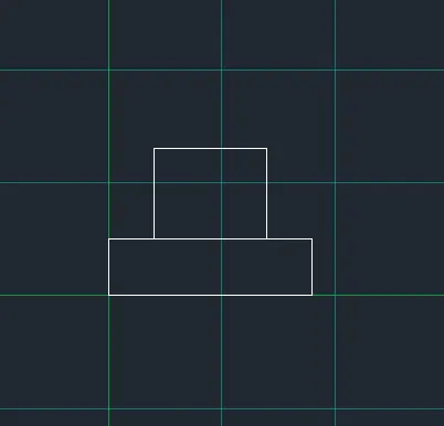
Step-2: Create the another REC Command
- Specify the first corner point which is 0.05 units from the starting point of second rectangle.
- Enter the length of rectangle as 0.4 units the width of rectangle as 0.4 units.
- Erase the unwanted lines in Intermediate portion.
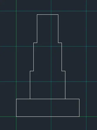
Step-3: Line is drawn from the corner of third rectangle, command "L"
- Give the length as 1.15 units
- Move cursor downwards and give value 0.15 units and right and give length as 1.15 units.
Step-4: Fifth rectangle is drawn using REC command
- Specify the first corner point at a distance of 0.05 from the third rectangle
- Give the length as 0.3 and width as 0.6
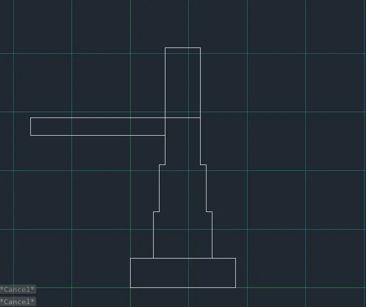
Step-5: from the line drawn in step 4, at a distance of 0.3, draw another line with the distance of 0.15 units vertically and 0.3 units horizontally.
- Continue it two more times, until 3 steps are created.
- Then draw the another rectangle by using REC command.
- Then give length is 0.3m and width is 0.05m.
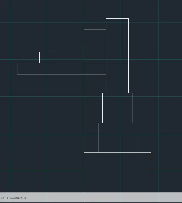
Step-6: Draw the fifth rectangle above the steps.
- Specify the corner point as the corner of fourth rectangular
- Click on dimension -give length as 0.3 units and with as 1 unit.
- Erase the unwanted line by "trim"
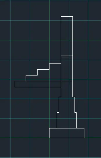
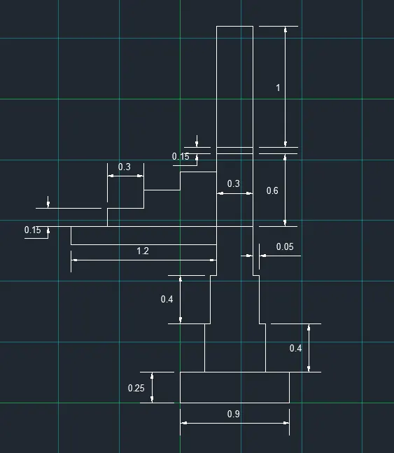
Step -7: Give the dimension to the drawing by using DIMLINEAR command.
RESULT FOR C/S OF LOAD BEARING WALL WITH SPREAD FOOTING
2) C/S OF ISOLATED FOOTING:
AIM:
To draw the c/s of isolated footing.
Commands Used:
- Line
- Trim
- Offset
Procedure:
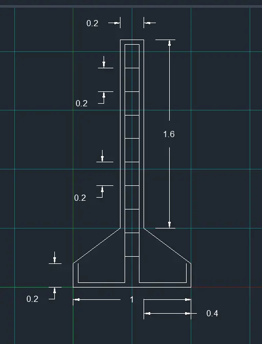
Step1: - Draw a line with command "l" and give 1 units.
- Give command "l" and give the relative coordinates as @ 0,0.15
- Give the next coordinate as @ 0.38,0.25.
- Next coordinate is given as @0,1.6
- Give @ 0.28,0
- Next coordinate @ 0,-1.6
- Next coordinate @ 0.38,-0.25
- Next coordinate @ 0,-0.15 or close.
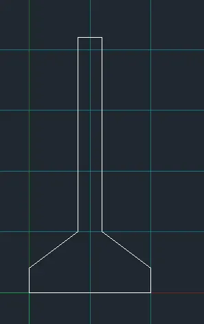
Step-2: Use Offset command @ distance 0.04
- Give the command of "o" and select the object and give the offset distance as 0.04.
- Do the same at the right and left bottom end.
- Trim the unwanted lines.
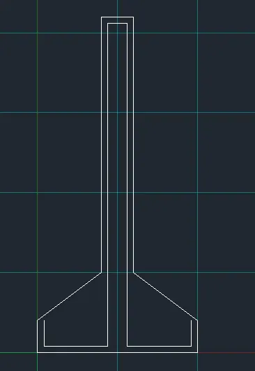
Step-3: Use Offset command @ distance of 0.2m
- Give command O in command box, then specify distance 0.2m select required object and make it in 9 times towards downward direction.
- Trim the excess lines
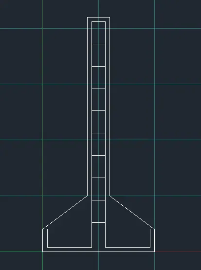
RESULT FOR C/S OF ISOLATED FOOTING:
3) LINE DRAWING OF BED ROOM BUILDING.
AIM:
To draw the line drawing of bed room building.
Commands Used:
- Line
- Rectangle
- Offset
- Trim
Procedure:
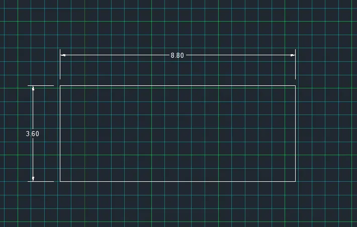
Step-1: Creating room size 8.8m x 3.6m by using REC command.
Step-2: Using offset command
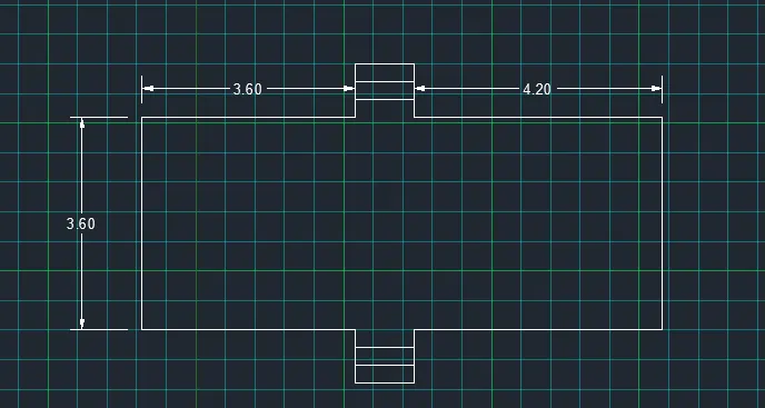
- Draw an off set using the command “O”
- In the command line enter “O” and specify the distance of3.6 units from the left bottom end.
- Draw an offset using the command “O” at a distance of4.2 units from the right bottom end.
- Draw an off set at a distance of 0.3 between the two line to bottom side.
- Repeat the same step and create two offsets.
- Do the same process in the top.
- Trim the unwanted lines.
Step-3:
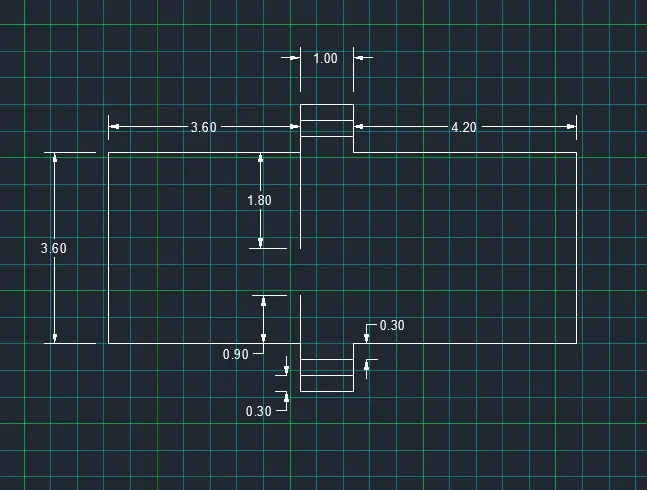
- Using line command draw a line at a distance of 3.6 units from the left bottom end to up-wards 0.9 units.
- Using line command draw a line at a distance of 3.6 units from the left top end to down-wards 1.8 units.
- Erase the unwanted lines.
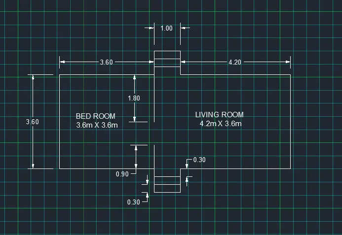
RESULT FOR BED ROOM BUILDING:
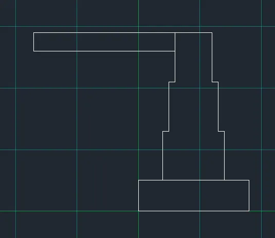
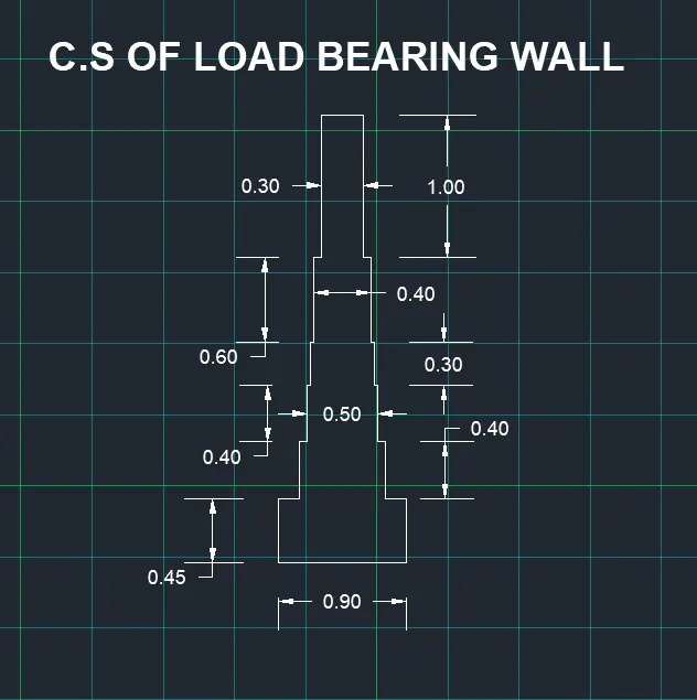
4) C/S OF LOAD BEARING WALLS SHOWING FOUNDATION DETAILS:
AIM:
To draw the c/s of load bearing walls showing foundation details.
Commands Used:
- Line
- Rectangle
- Trim
Procedure:
Step-1: Creating rectangle by using REC command
- Specify the first corner point as (5,5).
- Specify the length of rectangle =0.9 units in command box.
- Specify width of rectangle =0.45 units in command box.
- Then create another rectangle and specify dimensions.
- Specify the first corner point which is 0.15 units from the starting point of first rectangle.
- Enter the length of rectangle as 0.6 units the width of rectangle as 0.4 units.
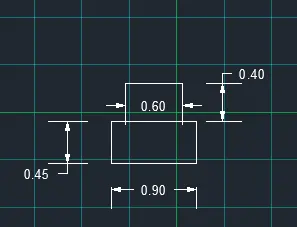
Step-2: Creating another Rectangle in three times for required specified dimensions:
- Specify the first corner point which is 0.05 units from the starting point of second rectangle.
- Enter the length of rectangle as 0.5 units the width of rectangle as 0.3 units.
- Specify the first corner point which is 0.05 units from the starting point of second rectangle.
- Enter the length of rectangle as 0.4 units the width of rectangle as 0.6 units.
- Specify the corner point as the corner of fourth rectangular
- Click on dimension -give length as 0.3 units and with as 1 unit.
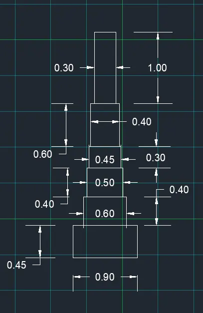
- Erase the unwanted lines in intermediate portions.
RESULT FOR C/S OF LOAD BEARING WALLS SHOWING FOOTING DETAILS:
5) ISOMETRIC VIEW OF STEPS:
AIM:
To draw the Isometric view of steps.
Commands used:
- Line
- Isometric plane
- Dimension tool
Procedure:
- To work with isometric view -command "ds" - snap off, grid off. Put isometric snap on .
- Make sure that ortho mode is on.
Step-1: From isometric drafting > select > Iso-plane left.
- Give command "l" and moving the cursor to -x direction(left) give 1unit .
- Moving the cursor to+ y direction (top), give 0.15 units.
- Moving the cursor to + x direction again give 1 unit and cursor to -y direction(downwards) give 0
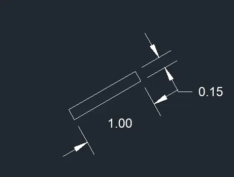
Step-2: Change the isometric drafting to Iso-plane Top.
- Move the cursor to back and give 0.3 units from the last drawn point.
- Move the cursor to right direction and give 1 unit.
- Move the cursor to front and give 0.3 unit.
Step-3: Change the isometric drafting to Iso-plane Right
- Copy the object drawn, ortho off .
- Command "co" and specify the base point and place it to new point.
- Repeat it until 4 steps are formed.
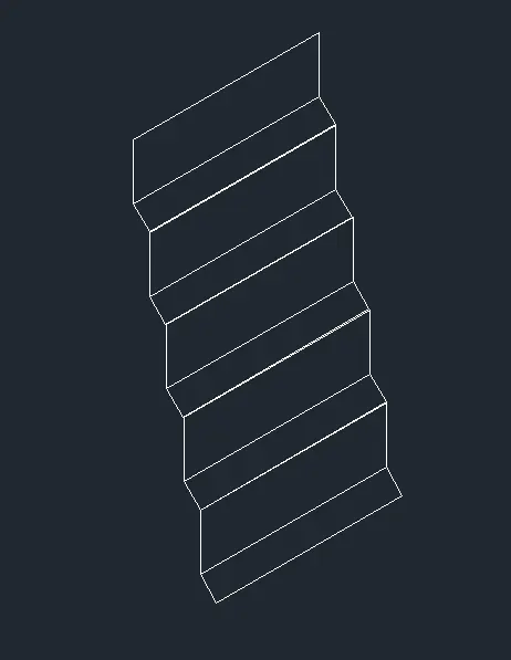
Step-4: With Using Iso-plane Right join the two ends with ortho off.
RESULT FOR ISOMETRIC VIEW OF STEPS:
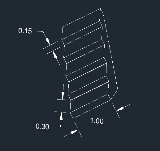
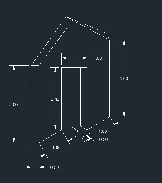
6) ISOMETRIC VIEW OF GABLE WALL:
AIM:
To draw the isometric view of gable wall.
Commands used:
- Line
- Isometric plane
Procedure:
- To work with isometric view -command "ds" - snap off, grid off. Put isometric snap on .
- Make sure that ortho mode is on.
Step-1: From isometric drafting > select > Iso-plane left.
- Give command "l" and moving the cursor to right give 1 unit
- Pointing the cursor upwards give 3 units
- Draw 0.3 units to left and 3 units downwards and 0.3 units to left.
Step-2: Change isometric drafting to Iso-plane right
- Use line command and draw line upwards of 2.42 units from the starting point of step-1.
- Draw 1 unit towards the right and 2.42 units downwards.
- Using isometric left again, using line command draw 0.3 units to left side and draw a line which intersects the top line.
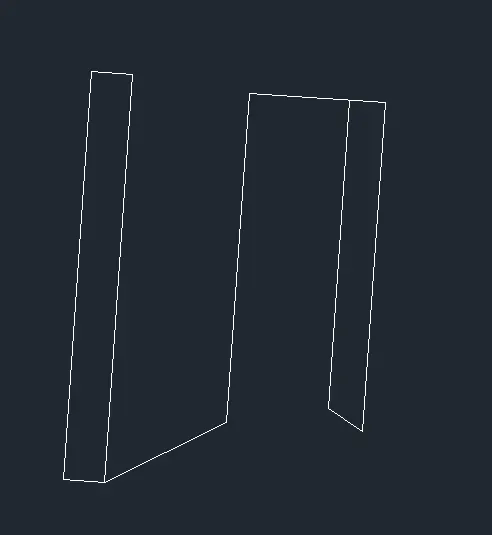
Step-3: Using iso-metric right with the line command draw 1.0 unit to right Side and 3.0 units upwards.
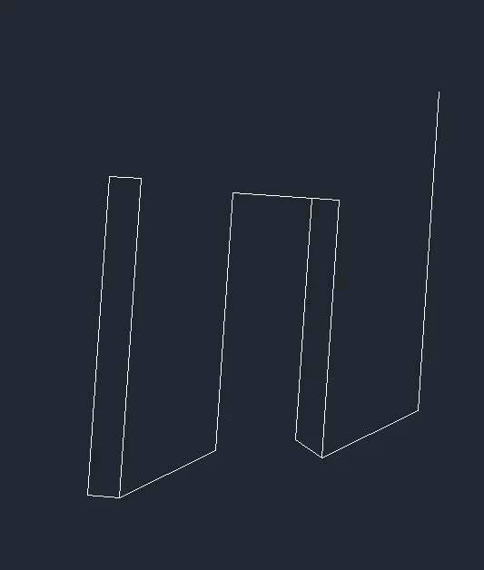
Step-4: By using the line command draw a line from bottom left corner @1.5 units and extend line 4 units upwards i.e., total 3.25 units from bottom.
Step-5: With ortho off, draw a line between the corner of left side and the projected line done in step 4 . Draw it to the other side also till it meets right corner.
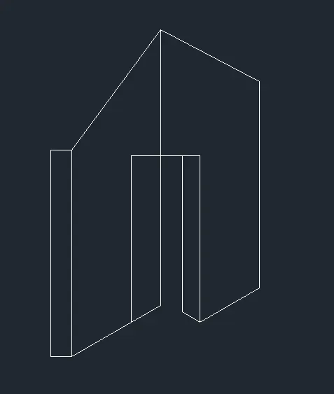
Step-6:
- Draw the vertical line with ortho on @0.3 and join the vertical line using line from left and right end same as in step-5.
- Remove unwanted lines by using Erase command.
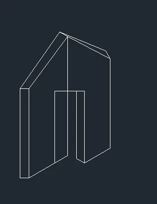
RESULT FOR ISOMETRIC VIEW OF GABLE WALL: