Structural Modelling using Etabs 2018
AIM
To model and analyze the G+7 residential building from the given architectural drawing using the ETABS 2018
INTRODUCTION
- ETAB or ETABS they mean the same. Its full form is extended three-dimentional analysis of building system.
- It is an engineering software product that caters to multi-story building analysis and design.
- ETABS offers a single user interface to perfom modelling, analysis, design and reporting.There is no limit to the number of modelling windows,model manipulation views and data views.
- Basic or advanced systems under static or dynamic conditions may be evaluated by using ETABS
- ETABS modelling is the genralization that multi-story buildings typically consist of identical or similar floor plans that repeat in the vertical direction.
- Modelling features that streamline analytical-model generation,and stimulate advanced seismic systems.
- Once modelling is complete,ETABS automatically genrates and assigns code-based loading conditions for gravity,seismic,wind and thermal forces.
OBJECTIVES
- To model an apartment with all seismic considerations,based on given architectural inputs
- To know how to check the seismic performance of an apartment using ETABS
PROCEDURE
STEP:1
- Open ETABS software
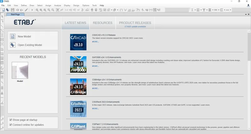
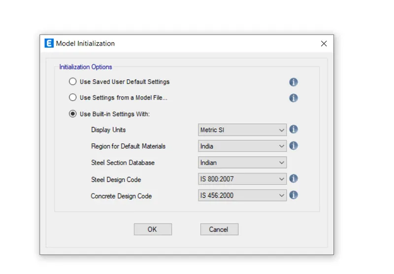
- Then click on the new model and choose use built-in setting with option
- Set the display unit as Metric SI or as per the requirement
- Then click ok
- New dialogue box will appear.
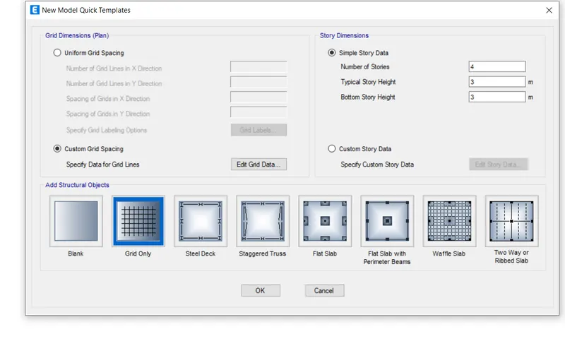
- Select the custom grid spacing and then select the edit grid data
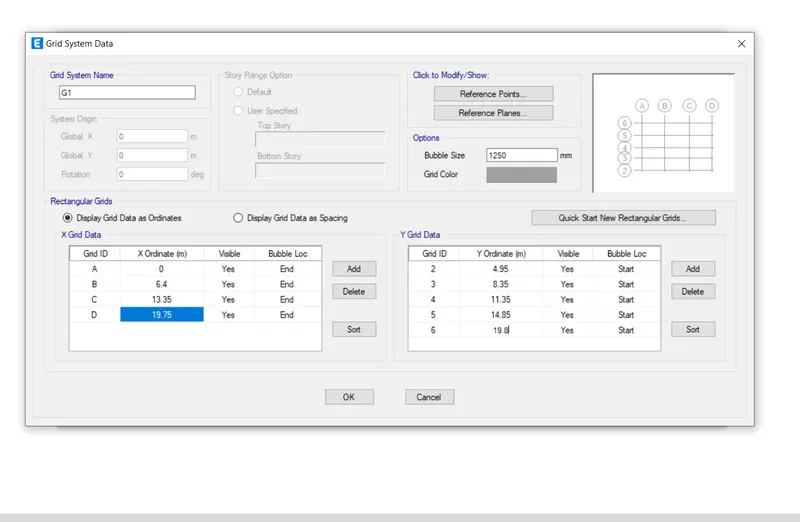
- click ok
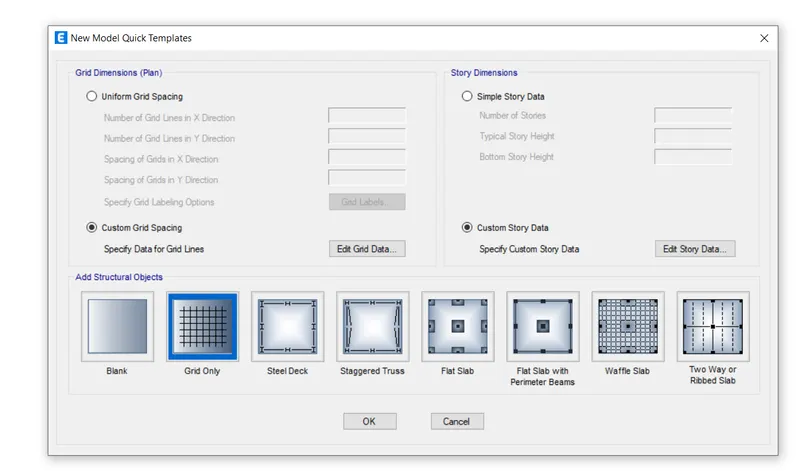
- Then select custom story data and select edit the story data
- After clicking the edit story data option there will be another dialogue box named as the edit story data, and we need to add the stories upto the seventh floors
- Then make ground floor as master story and all other storys are similar
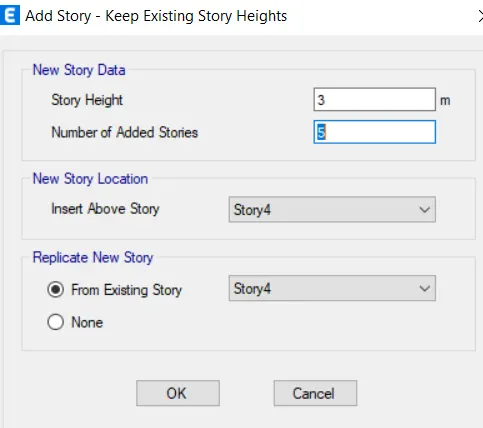
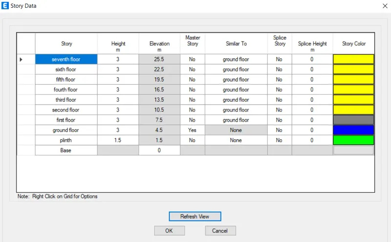
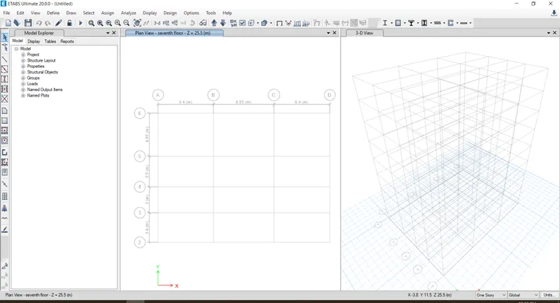
- The story and grids setup have been completed
- So the plan view and the 3D view has been shown below in the image
STEP:2
MATERIAL PROPERTIS
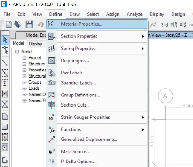
- Inorder to set the material first we need to go to the define option and there will be a drop-down list in that list there is another option called material properties
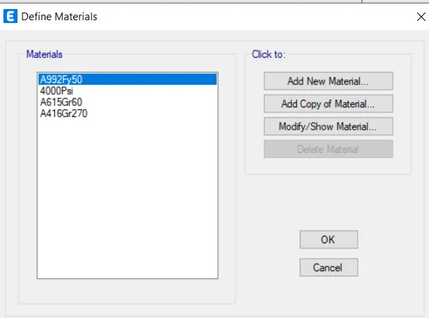
- After clicking on the material properety there will be another dialogue box named as define material, in that dialogue box just click on the option add new material
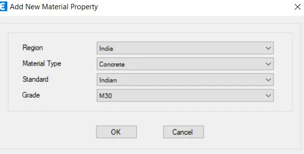
- New window will appear now define material type as concrete and grade as M30
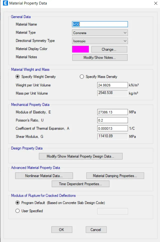
- Click ok
- Add new material property
- New dialogue box will appear
- Select materail type and grade
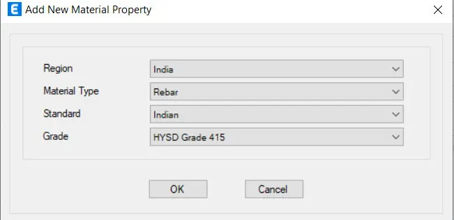
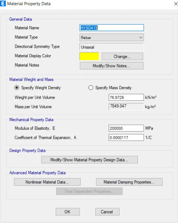
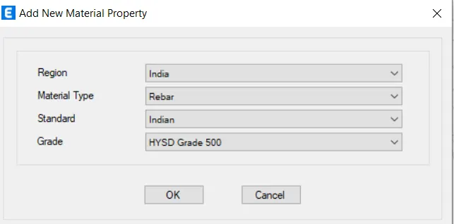
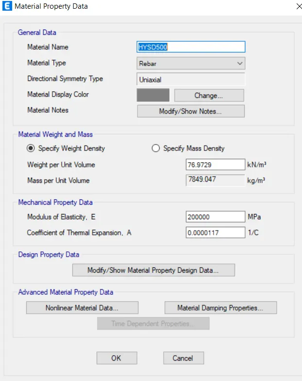
- HYSD 500 for the longitudinal reinforcement
- HYSD 415 for the shear reinforcement
STEP:3
COLUMN
- Now we have to design the frame properties
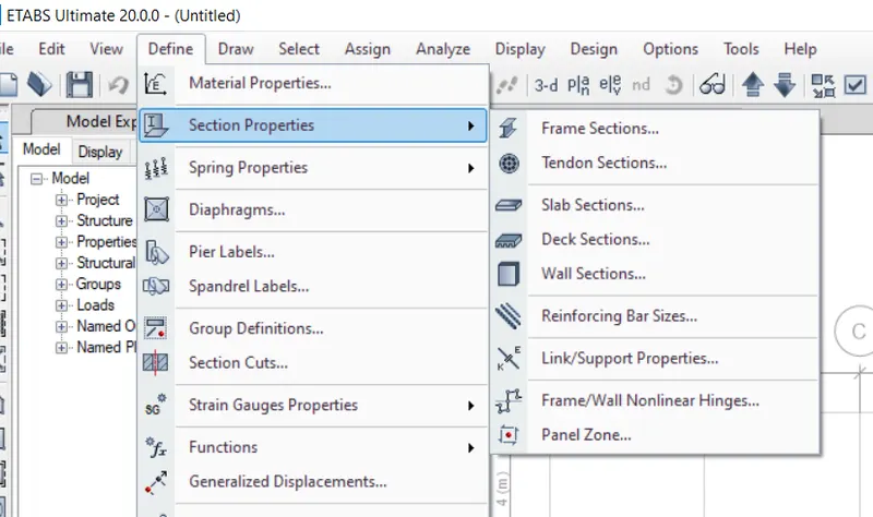
- Go to the define tab there will be a drop-down list ,select section properties and from that select frame properties
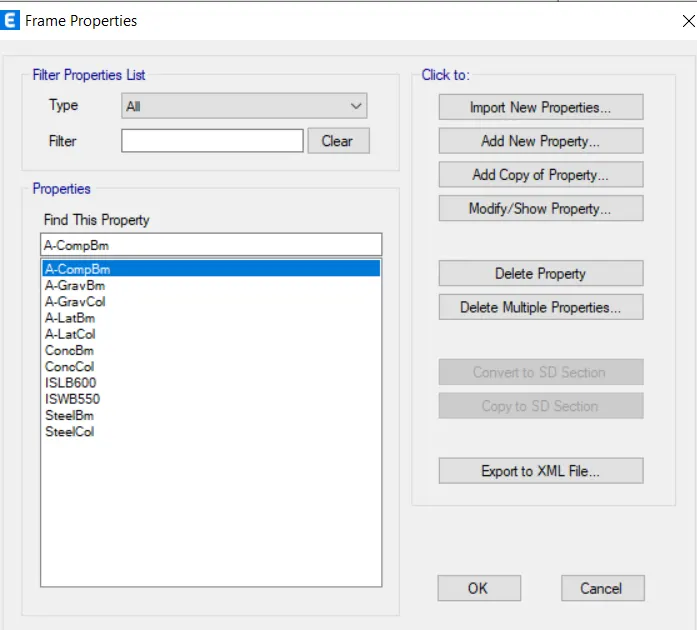
- A new dialouge box will appear ,in that select add new property
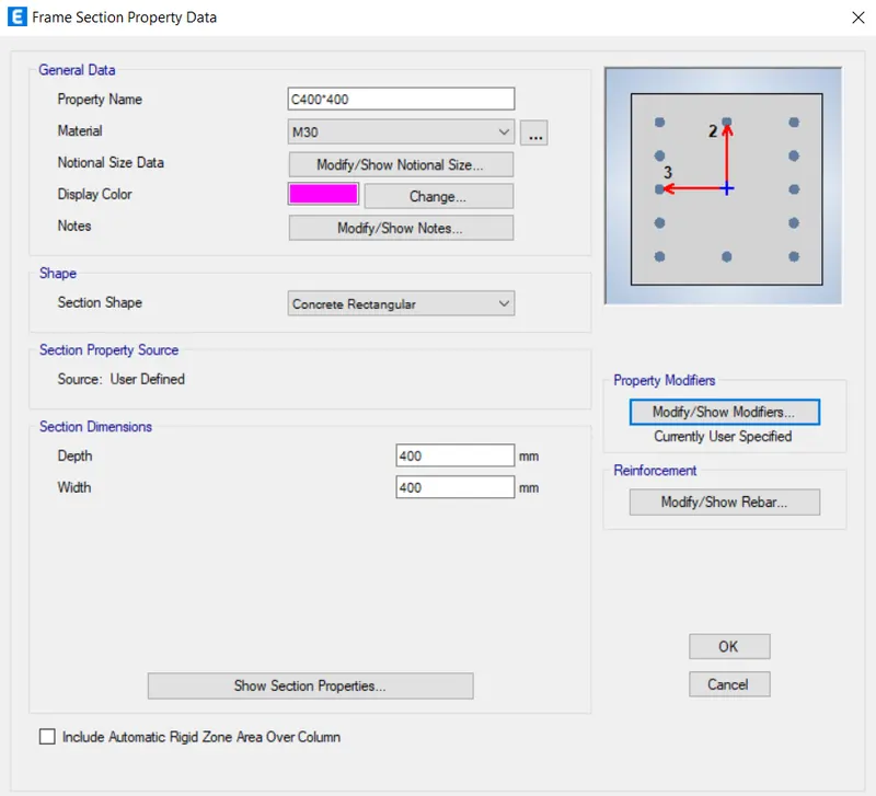
- Then select the rectangular concrete section,rename it C400*600
- Change the property as M30 and change the size as C400*600
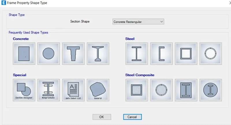
- After that another dialouge box opens
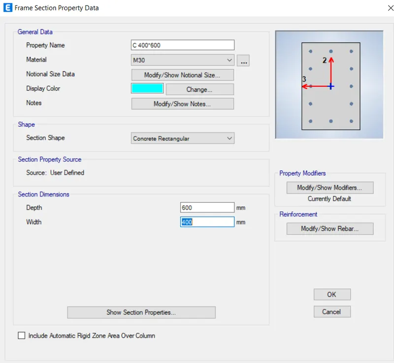
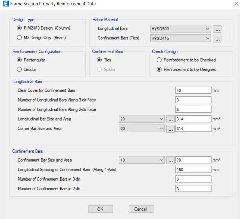
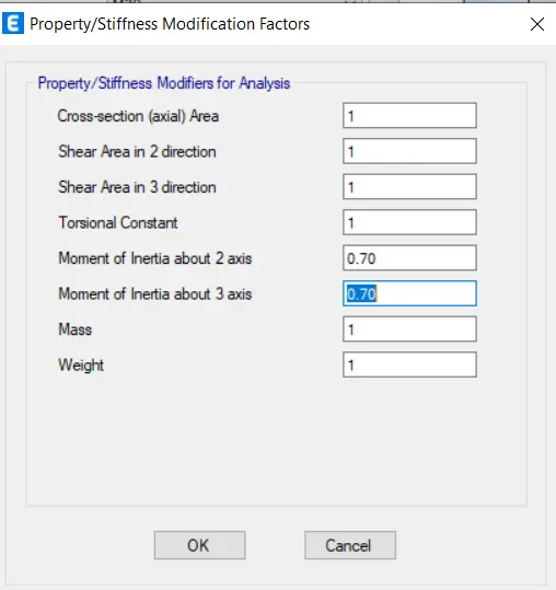
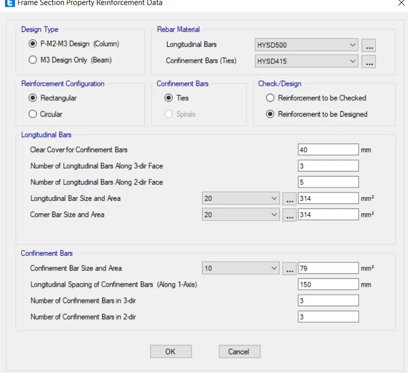
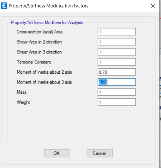
- Click on the modify/show modifiers, another dialouge box will appear on the screen fill all the relevant data
BEAM
- Now we have to design the frame properties
- Go to the define tab there will be a drop-down list ,select section properties and from that select frame properties
- A new dialouge box will appear ,in that select add new property
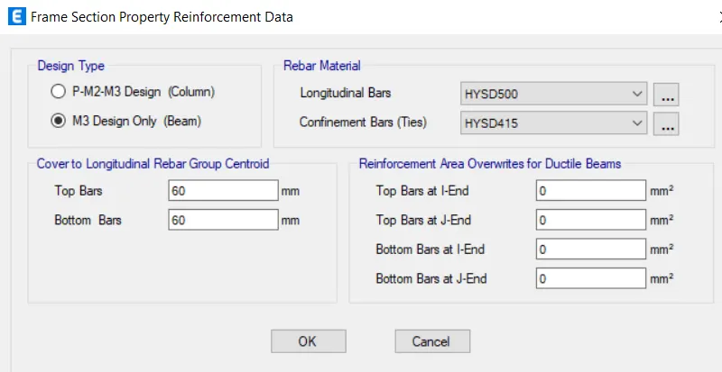
- Then select the rectangular concrete section,rename it B250*450
- Change the property as M30 and change the size as B 250*450
- After that another dialouge box opens
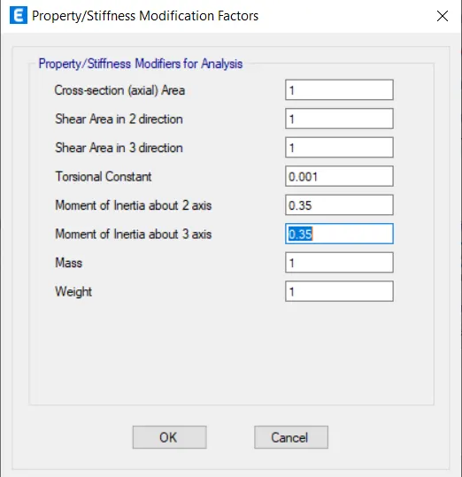
- Click on the modify/show modifiers, another dialouge box will appear on the screen fill all the relevant data
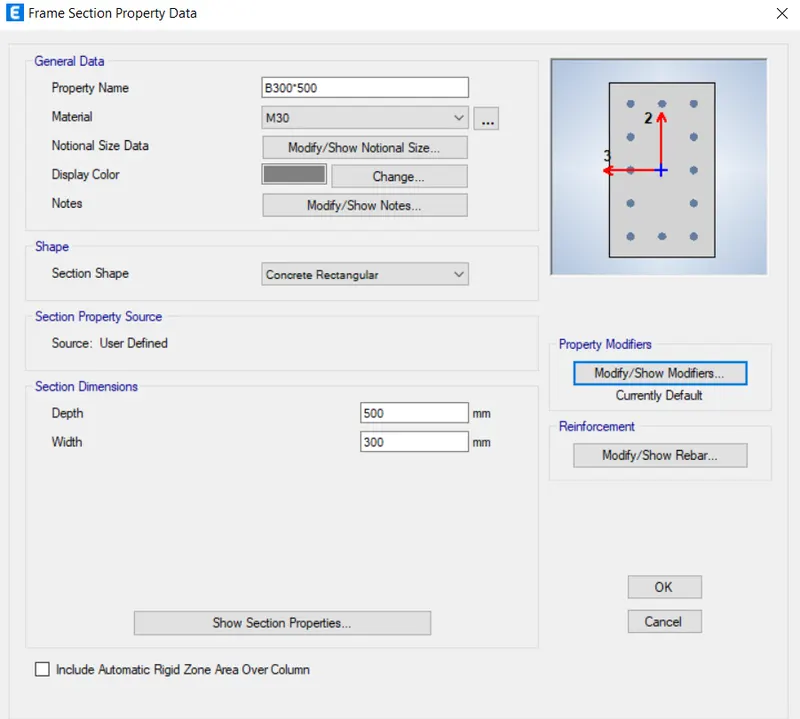
- Following the same procedure we will add another beam
- B300*500
SLAB
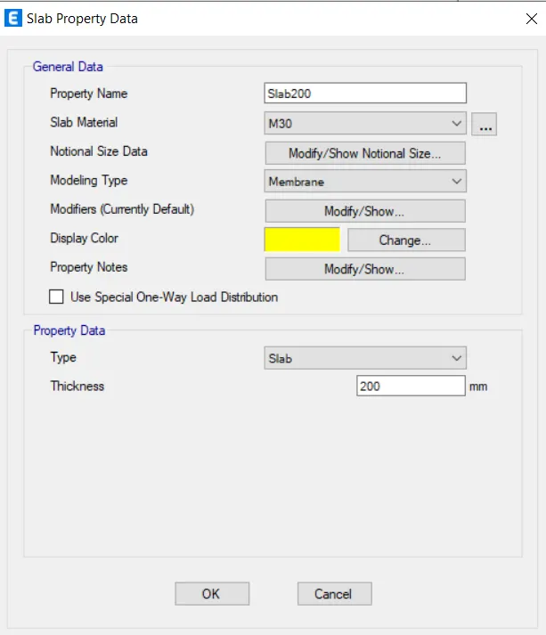
- Then go to define select section properties from that select slab section
- New window appears
- Select add new property,nwe dialouge box will appear
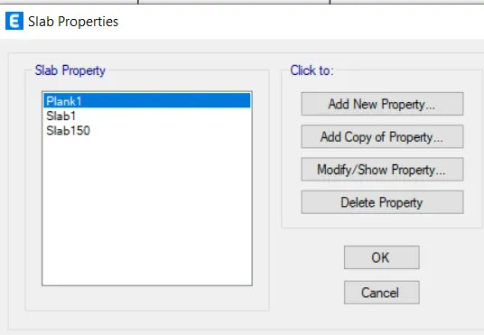
- Rename it as slab125, modelling type as membrane and change thickness as 125mm
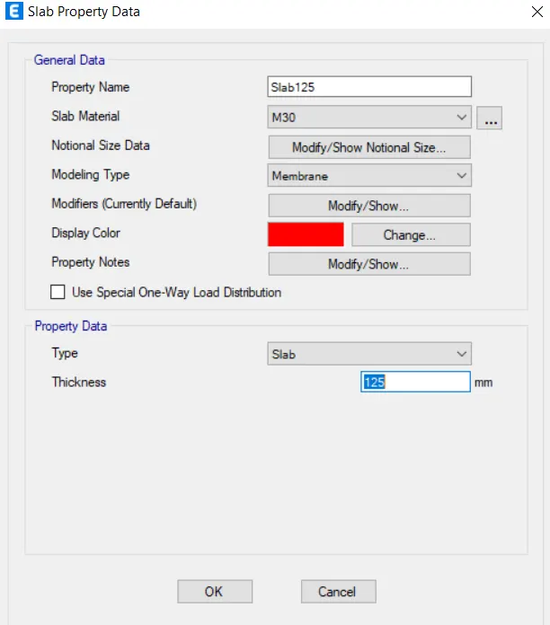
- Similarly we will be adding the slab for the staircase of 200mm thickness
- Do the same procedure that we have done for the slab 125mm
SHEAR WALL
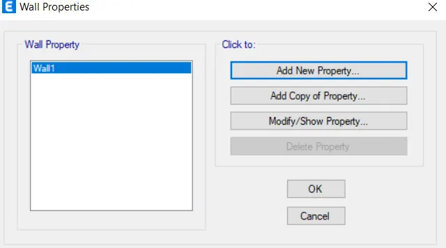
- Go to define --->section properties-->wall section
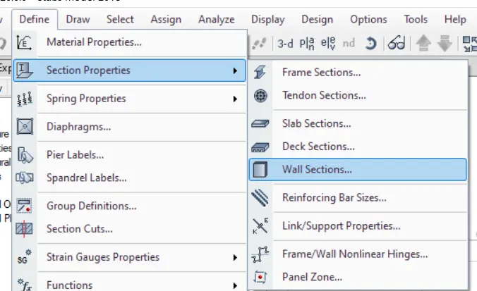
- Another dialouge box will appear , in that select add new property
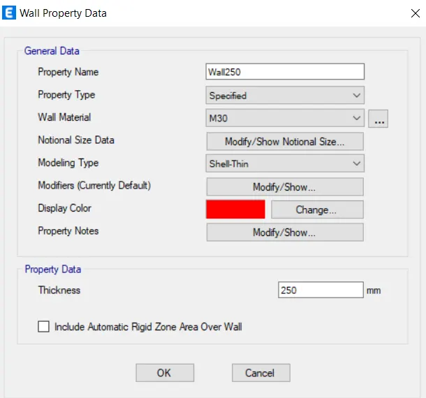
- Another dialouge box will appear, add relevant data
STEP:4
- Draw structural members
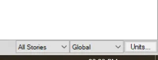
- For that first select the mode as all stories at the right bottom corner
- So in order to use this tool to place the columns in a quick way so first go to the left side of the screen there is a option of quick draw columns
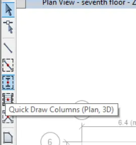
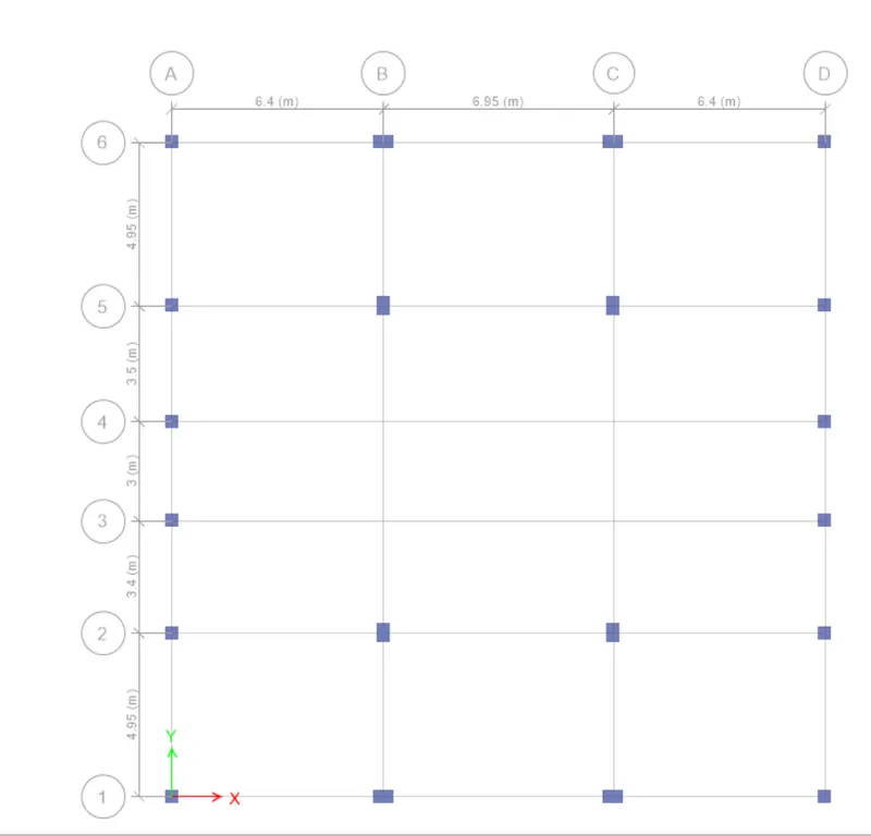
- Place the column
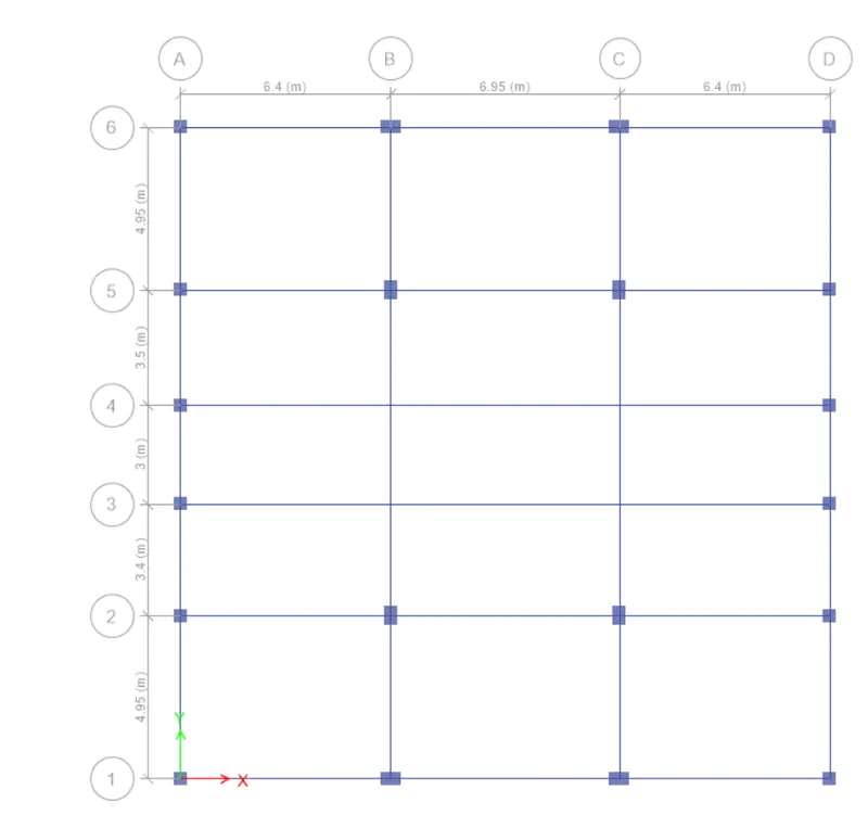
- Similarly add the beams
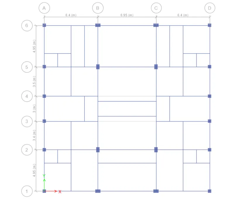
- Now similarly add the secondary beams
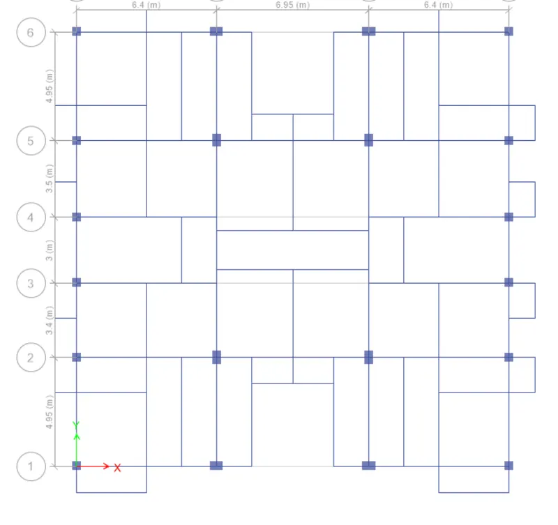
- Now add the secondary beams and balcony
- Add shear walls in their appropriate locations just by using etabs quick tools to draw walls and this tool is present at the left side of the screen
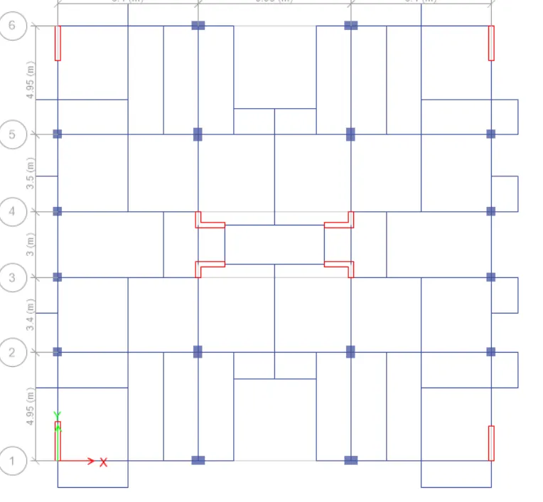
- Adding slab just by using the option quick draw plan/wall that are present in the left side of the screen
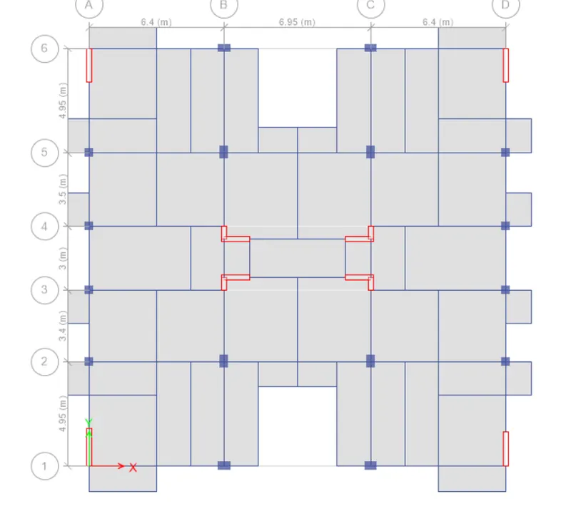
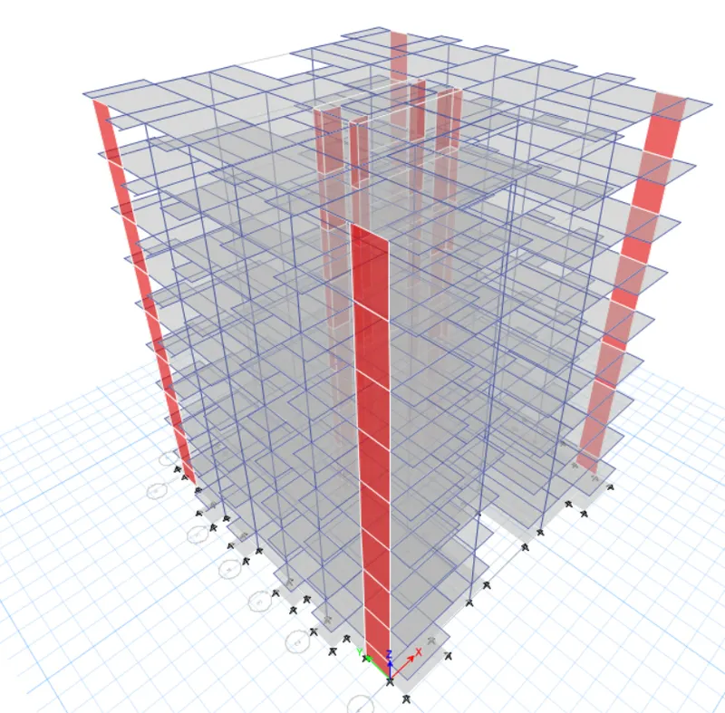
- Now we have to fix the connections at the base plan
- so in order to do that first we need to go to the base plan and then select all the joints
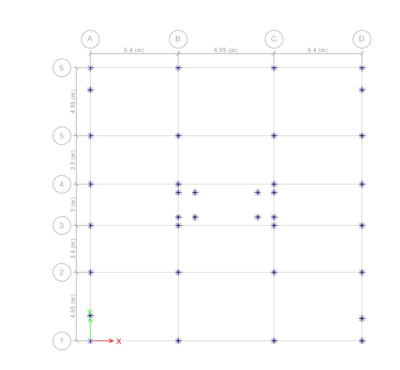
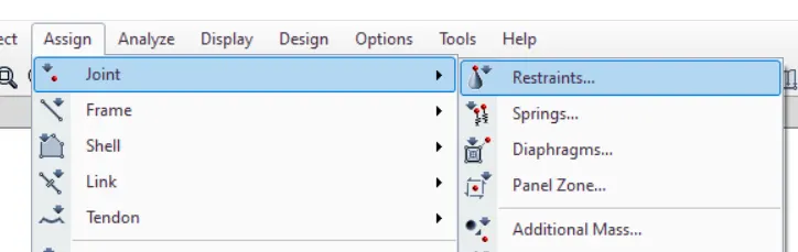
- After that just go to assign-->joints--> restraints
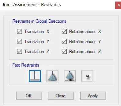
- another dialouge box will appear ,choose connection as fixed
STEP:5
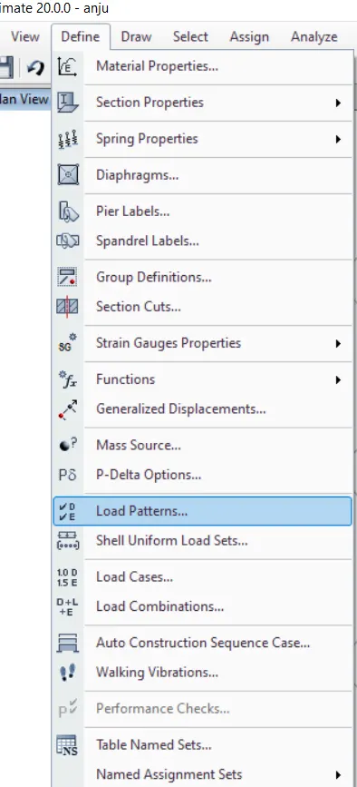
- Click on the define and from that select the load patterns
- Define the loads like dead load , live load , brick wall load and earthquake load in x direction and eccentric earthquake loads in positive x and negative x and same loads in y direction also mension IS codes of respective loads
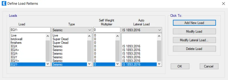
- Click on modify lateral load, set range from base to seventh floor,change direction and eccentricity ,seismic zone factor as 1 and time period as 0.5 seconds
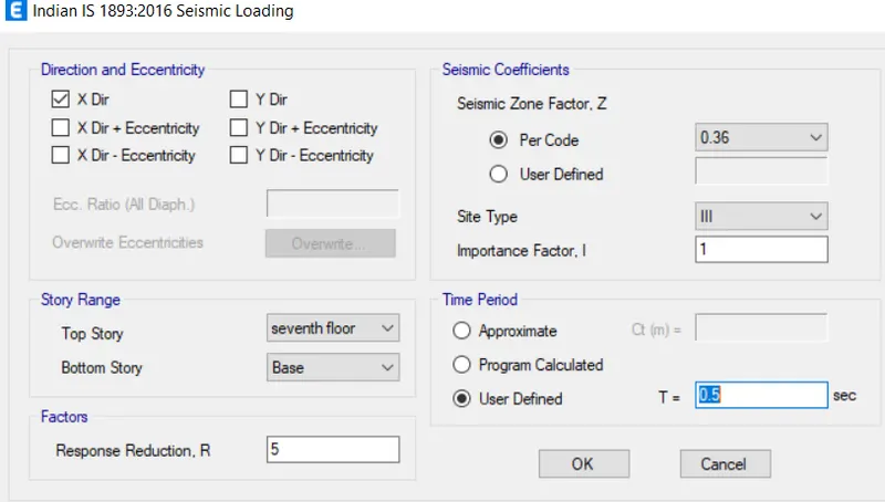
- Do the same for all the earthquake loads
- Now we will be assigning the brick wall load to the structure
- For that go to define -->frame loads -->distributed
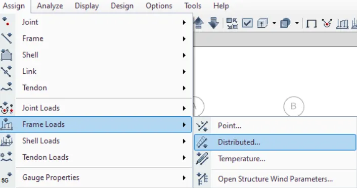
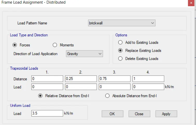
- A new dialouge box will appear
- In that give brickwall load as 3.5KN/sq.m
- Then apply
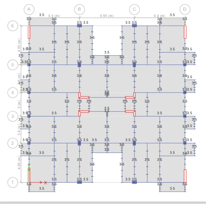
- After applying dead loads to the structure now we will be applying live load
- For that go to assign -->shell loads-->uniform
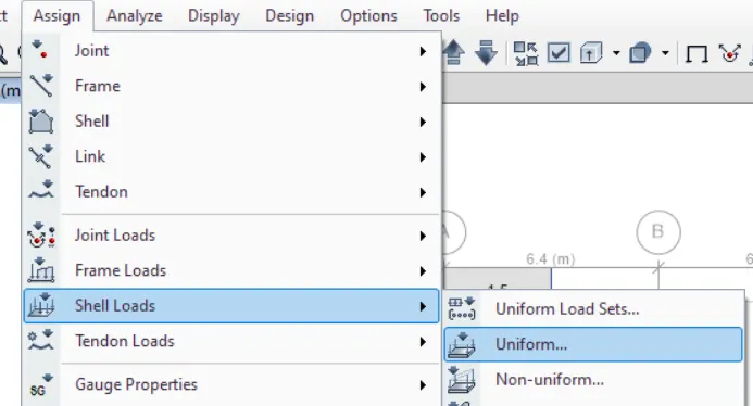
- A new dialouge box will appear and fill it with relevant data
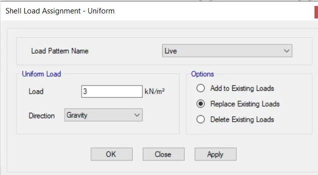
- As we know that according to the is code 875 there is a provision which says that in residential buildings that the live load for rooms must be 2KN/sq.m
- And for the bathroom it should be3 kN/sq.m
For Rooms : 2KN/sq.m
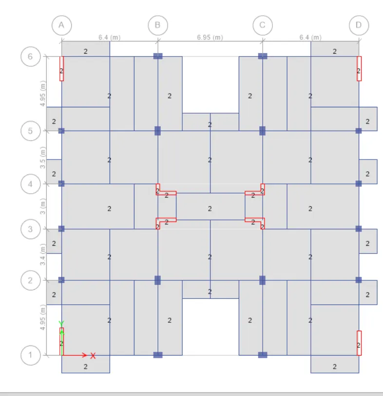
For Bathrooms, staircase, lift:3KN/sq.m
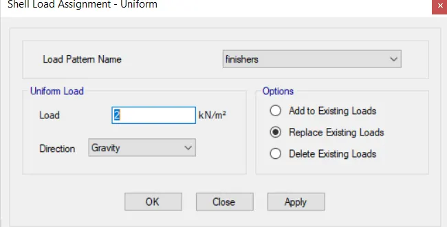
- After that need to add floor finishes to the structure
- For that go to the assign-->shell loads -->uniform
- A new dialouge box will appear and fill it with relevant data
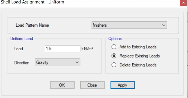
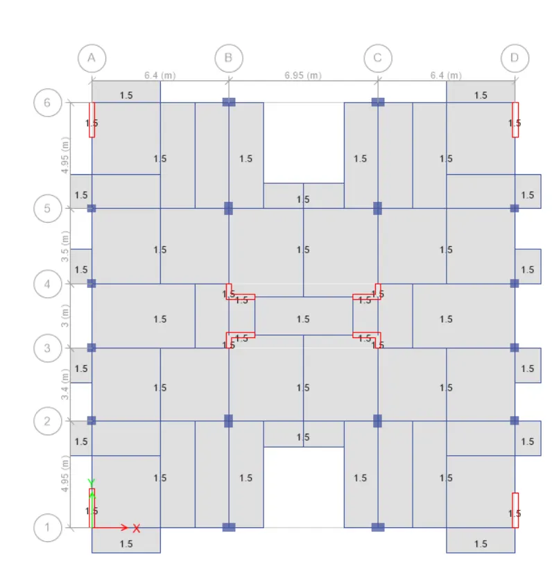
- After assigning the floor finish load now we will be doing the live load reduction factor according to the code
- For that go to design -->live load reduction factor
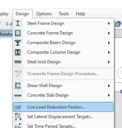
- A dialouge box appears and in that select the user defined then select define
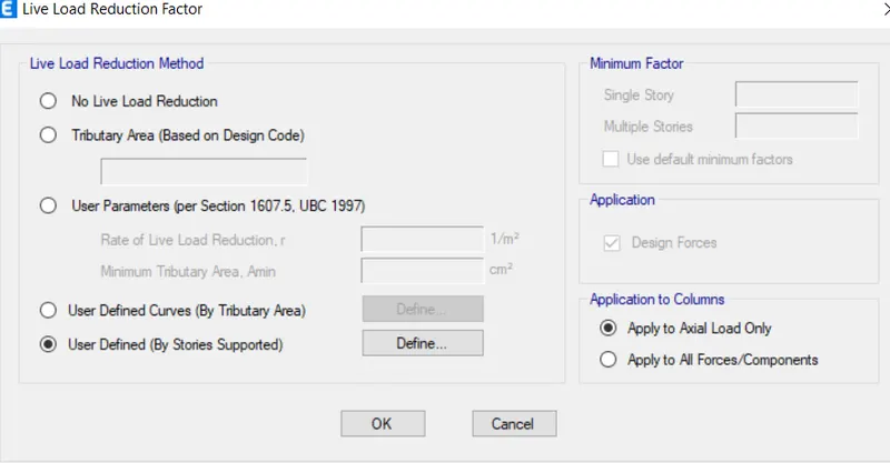
- Then another dialouge box appears and fill it with relevent data
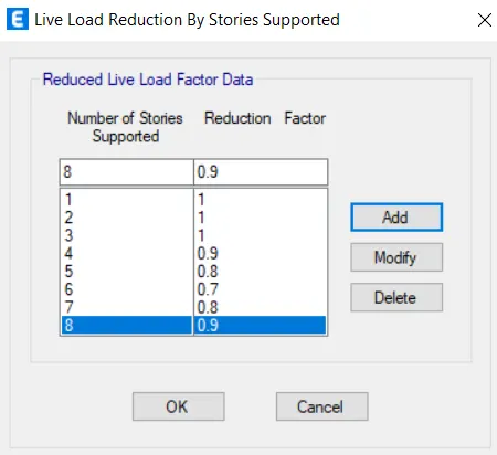
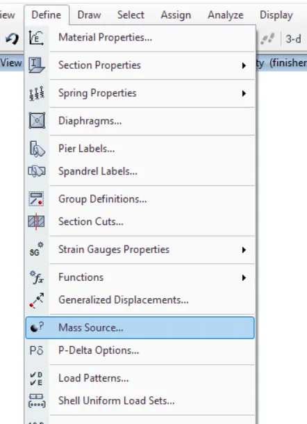
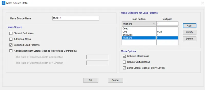
- Now we have to assign the mass source for this structure
- Another dialouge box appears and fill it with appropriate data
- After assigning mass source now we have to assign the diaphragm
- For that first we need to select
- then go to assign--shell-->diaphragm
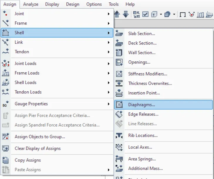
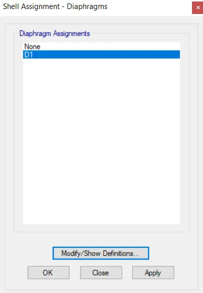
- There will be another dialouge box select D1 and click on the apply and then click ok
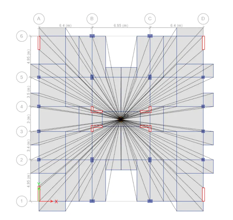
- After assigning the diaphragm now we have to assign the load combinations
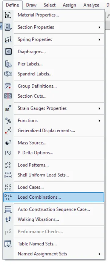
- For that go to define ---> load combination
- There will be another dialouge box in that click on the option add default combos
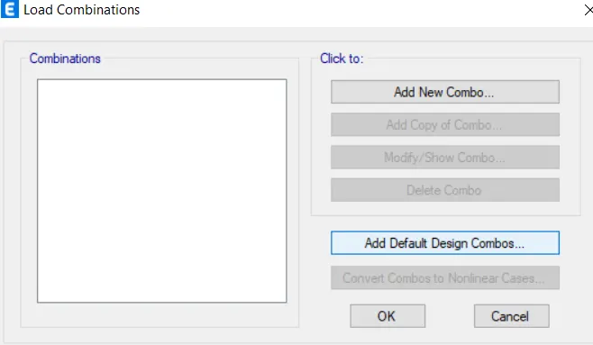
- Another dialouge box appears in that click on the option concrete frame design and concrete shear wall design , then click on the option ok
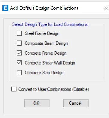
- Another dialouge will appear in that all ETABS generation load combination will be there

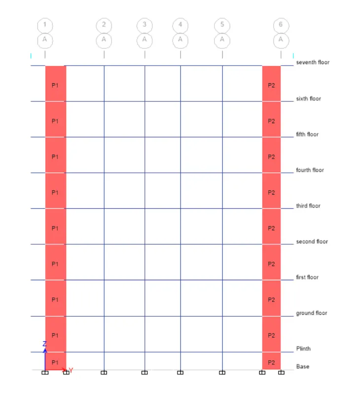
- Now select the pier labels and in order to do that first we need to go to the assign menu --->shel-->pier label
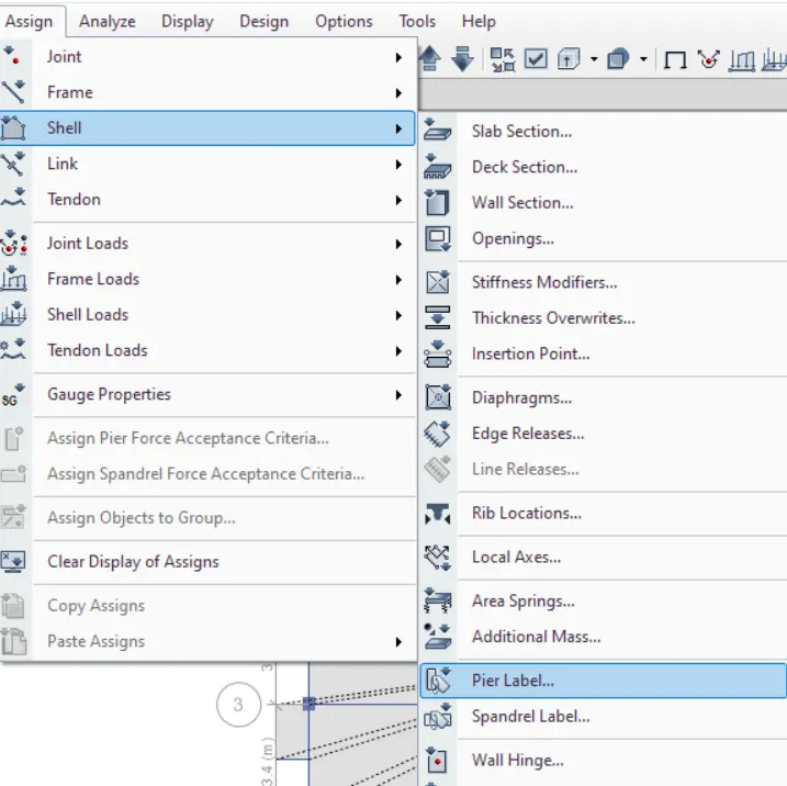
- After that another dialouge box named as pier labels will appear in that dialouge box just add the labels
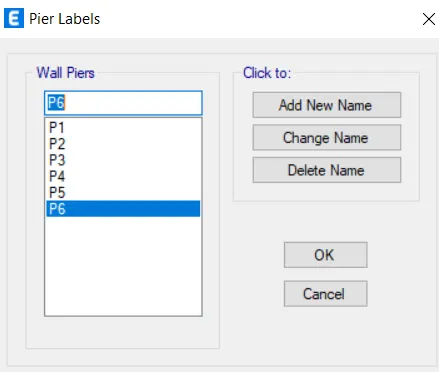
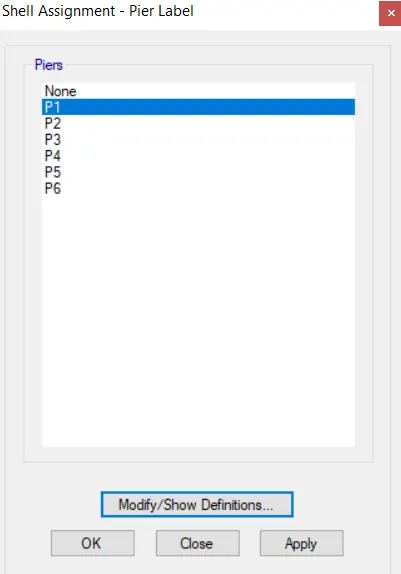
- Then assign the pier labels accordingly
STEP:5
Modal Analysis
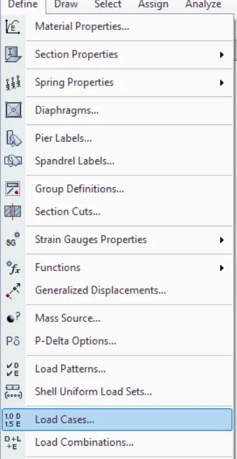
- Go to define -->load cases
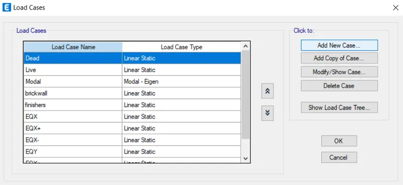
- New dialouge box will appear in that select add new case
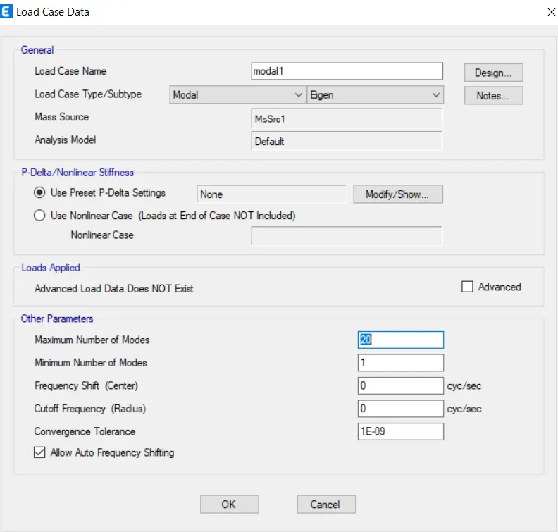
- Another dailouge box will appear enter the relevant data required
- After this we will be assigning spectrum analysis
- For that go to define --> functions-->spectrum analysis
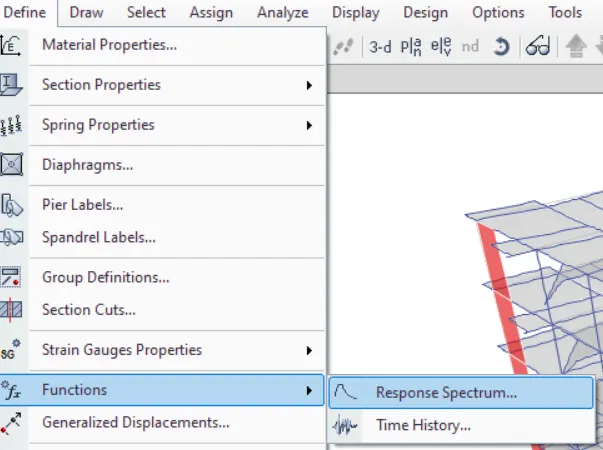
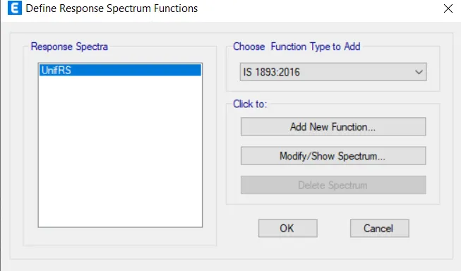
- A new dialouge box will appear in that choose ia 1893-2016 and click on th add new function
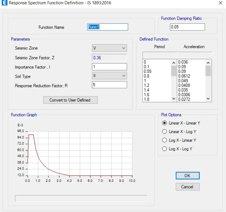
- After clicking that new dialouge box will appear fill it with relevant data
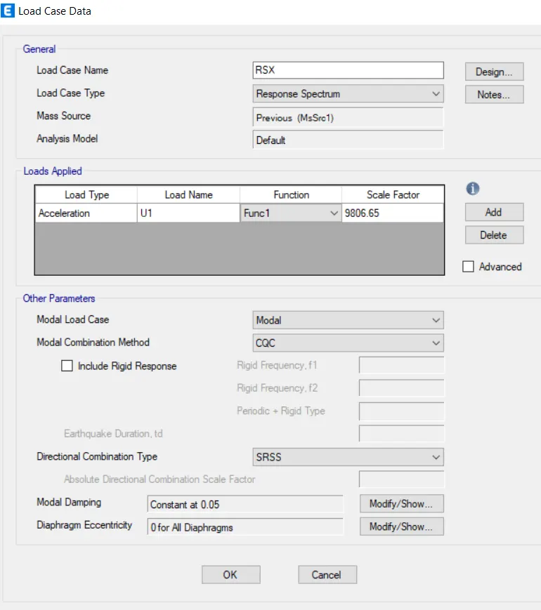
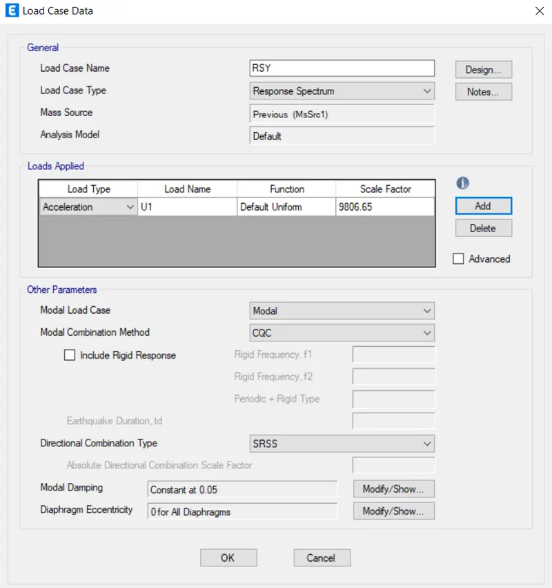
The response spectrum load case in X direction :RSX
The response spectrum load case in Y direction :RSY
- Now after this we will check the model and will run the analysis
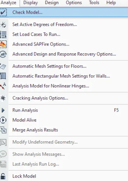
- So for checking the model go to analyze -->check model
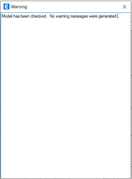
- Now the model is checked and there are no warnings
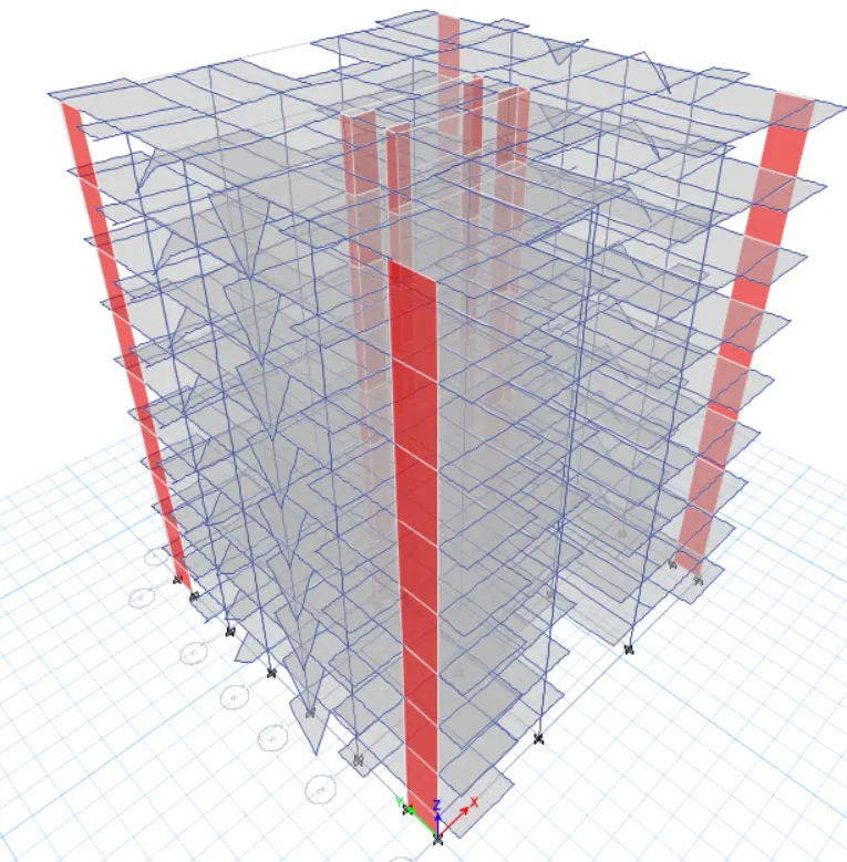
- After checking the model with no warning do the run analysis
STEP:6
Reviewing the analysis results
Base Shear Check
- To check base shear go to diaplay -->show table
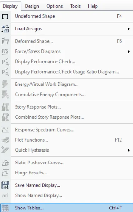
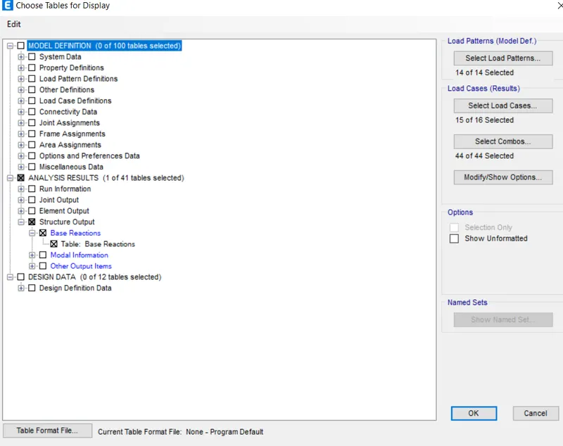
- Then another dialouge box will appear in that select analysis result --> structure output -->base shear
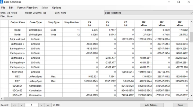
- Base reactions table will appear
- According to the codebook it is said that the response spectrum base shear must be at least equal to the same that is obtained by the linear analysis
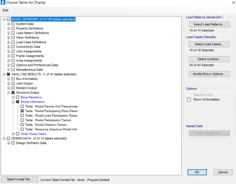
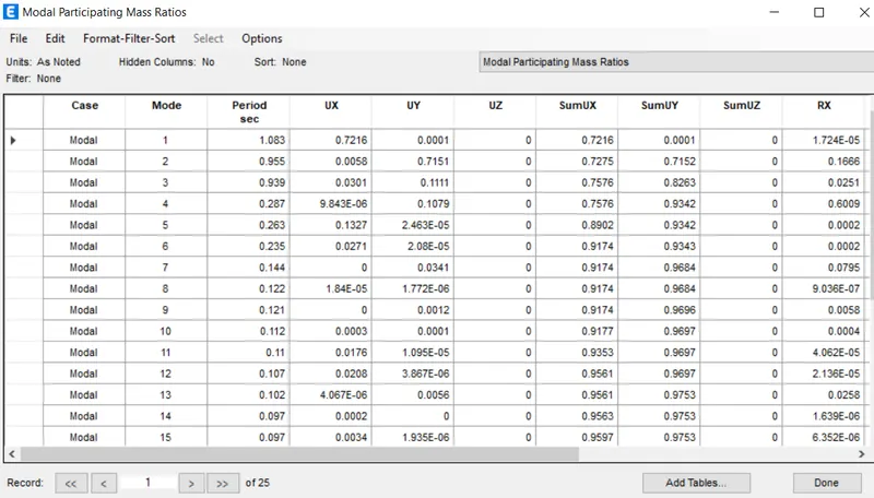
- Go to the display tables and select the modal participating mass ratio
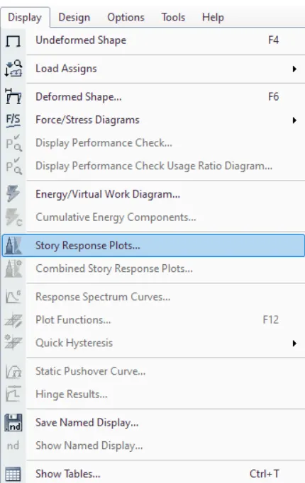
- Go to display ---> story response spectrum
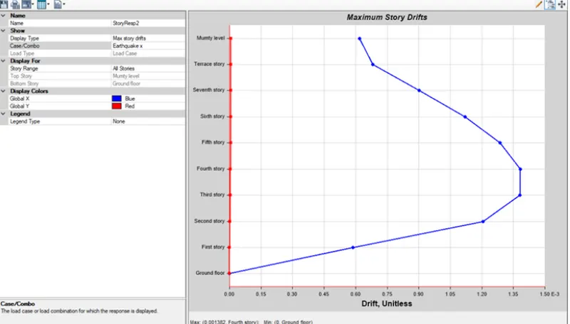
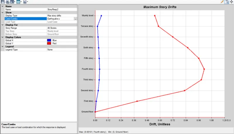
- select story response as maximum story drifts in both x and y direction amd it should be not more tham4%
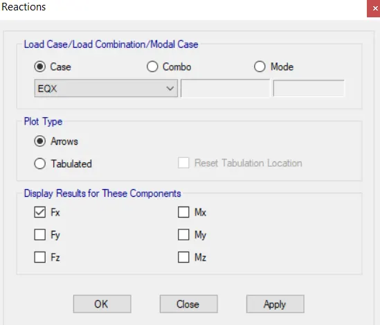
- Now open the reaction tab from the top screen there is a tab click on that tab or just press F7
- New dualouge box will appear , in that select the earthquake towards the x direction
- Then just click apply and then ok
RESULT
The G+7 residential building has been modelled and analyzed successfully using the ETABS 2018