Creating a Floor plan, Footing detail and Isometric view using AutoCad
AIM
To create a Floor plan , Footing detail and isometric view using AutoCad
INTRODUCTION
In this project we are drawing using rectangle, polygon and certain modifiying tool.
As the name modify tools is used to modify the existing objects and lines .AutoCAD has a whole range of modify tools .It performs editing operations such as erase, move and trim on the objects in a drawing. The most common of these tools are located on the modify panel of the Home tab.
PROCEDURE
STARTING AUTOCAD
- Select AutoCAD 2023 from the start menu
- In the command line type in:STARTUP then enter
- Enter the new value of startup:1
- Then from application menu select NEW
- 'Create New Drawing' dialog box will appear and from that select the Imperial System in the 'Start from the Scratch' option
- Next select the 'Decimal' unit system from the Advanced setup option
- set the limits by entering LIMITS in the command tab.lower left corner is specified as 0,0 and upper right corner is specified as 200,200
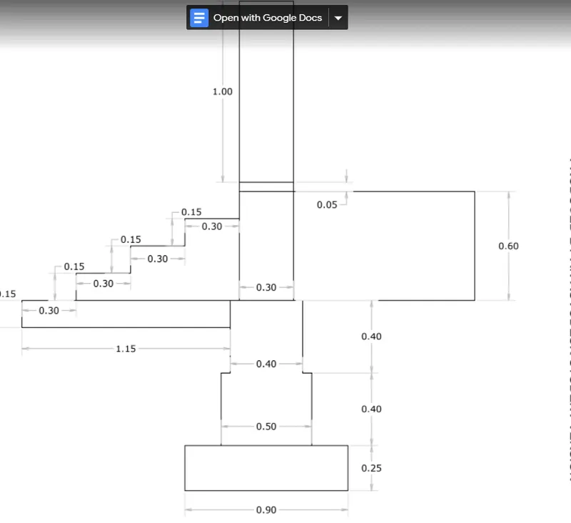
FIGURE 1
CROSSECTION OF LOAD BEARING WALL OVER SPREAD FOOTING
PROCEDURE
STEP1
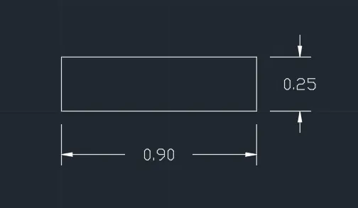
- Creating a rectangle
- In the command box REC enter
- Then specify the first point as 1,1
- Specify the length of the rectangle 0.9 in the command box
- Specify the width of the rectangle 0.25 in the command box
STEP2
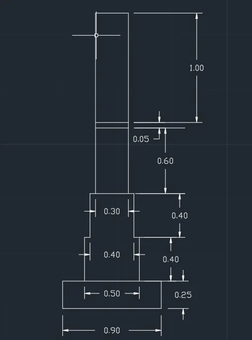
- Using direct distance method
- Select the line tool by entering LINE or L in the command tab
- Specify the first corner point which is 0.2 units from the starting point of the rectangle drawn
- Enter the length of point 1 as 0.40 in the command line towards +ve y-axsis
- Enter the length of point 2 as 0.05 in the command line towards +ve x-axsis
- Enter the length of point 3 as 0.40 in the command line towards +ve y-axsis
- Enter the length of point 4 as 0.05 in the command line towards +ve x-axsis
- Enter the length of point 5 as 1.65 in the command line towards +ve y-axsis
- Enter the length of point 6 as 0.30 in the command line towards +ve x-axsis
- Enter the length of point 7 as 1.65 in the command line towards -ve y-axsis
- Enter the length of point 8 as 0.50 in the command line towards +ve x-axsis
- Enter the length of point 9 as 0.40 in the command line towards -ve y-axsis
- Enter the length of point 10 as 0.50 in the command line towards +ve x-axsis
- Enter the length of point 11 as 0.40 in the command line towards -ve y-axsis
- Press escape
- Select the line tool by entering LINE or L in the command tab
- Connect point 4 and 7
- Offset that connect line to a distane of 0.60 and 0.65
STEP 3
- Select the line tool by entering LINE or L in the command tab
- From step 2 point 3 draw a line of 1.15 units
- Move the cursor downwards and give the value 015 units and move right and give the length as 1.15 units
- press escape
- Select the line tool by entering LINE or L in the command tab
- From the line drawn from point 3, at a distance of 0.15 vertically and 0.3 horizontally
- continue this 2 more times until 3 steps are created
FINAL RESULT
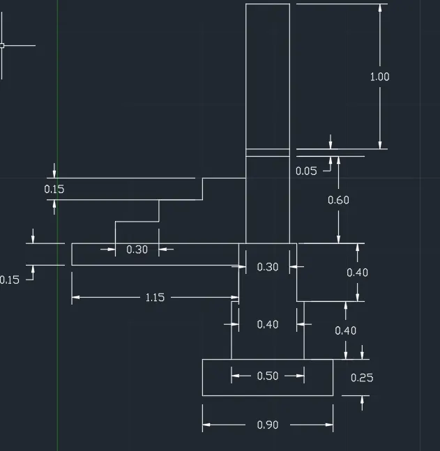
FIGURE 2
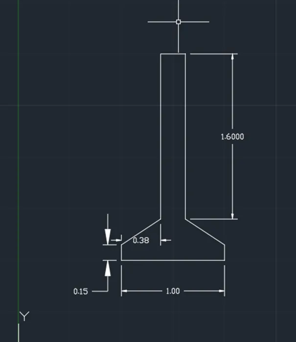
CROSSECTION OF ISOLATED FOOTING
PROCEDURE
STEP1
- Select the line tool by entering LINE or L in the command tab
- Using relative coordinates
- specify the first point as 1,1
- specify the next point as @0,0.15
- specify the next point as @0.38,0.25
- specify the next point as @0,1.6
- specify the next point as @0.24,0
- specify the next point as @0,-1.6
- specify the next point as @0.38,-0.25
- specify the next point as @0,-0.15
- close
STEP2
- Here we are using offset tool
- By typing O enter in the command line and giving distance of 0.04
- Select the object bottom line to upwards
- Do the same from left and right side
- Trim the unwanted lines
- Then take offset from the top line with an offset distance of 0.2
- Use multiple option and make 9 such lines and trim the unwanted lines
FINAL RESULT
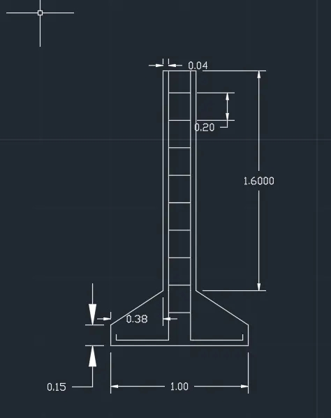
FIGURE 3
LINE DIAGRAM OF A TWO BEDROOM BUILDING
PROCEDURE
- Creating a rectangle
- In the command box REC enter
- Then specify the first point as 1,1
- Specify the length of the rectangle 8.8 in the command box
- Specify the width of the rectangle 3.6 in the command box
- Using offset command
- In the command line enter "O" and specify the distance 3.6 from the left bottom end
- Again draw offset using the command "O" at a distance of 4.2 from the right bottom end
- Extend the two lines in the middle to top and bottom
- Draw an offset at a distance 0.3 between the two lines to bottom sides and repeat the offset two more times
- Repeat the same at top
- Trim the unwanted lines
- By using line command draw a line at a distance of 3.6 from the left bottom end to upwards 0.9
- Again By using line command draw a line at a distance of 3.6 from the left top end to downwards 1.8
FINAL RESULT
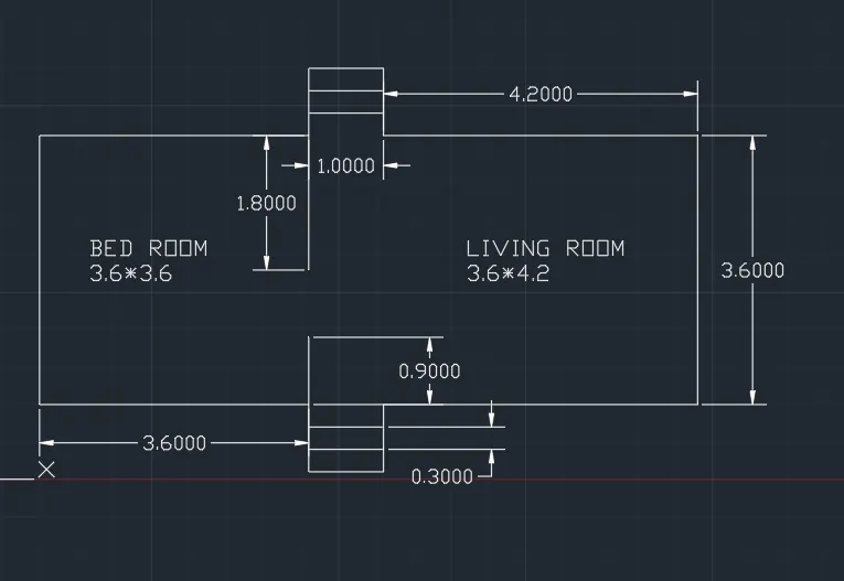
FIGURE 4
CROSSECTION OF LOAD BEARING WALL SHOWING THE DETAILS OF FOUNDATION
PROCEDURE
- FIRST RECTANGLE
- Creating a rectangle
- In the command box REC enter
- Then specify the first point as 1,1
- Specify the length of the rectangle 0.9 in the command box
- Specify the width of the rectangle 0.45in the command box
- SECOND RECTANGLE
- Creating another rectangle over the first one
- In the command box REC enter
- Specify the first corner point which is 0.15 from the starting point of first rectangle
- Enter the length of the rectangle as 0.6 and width of the rectangle as 0.4
- THIRD RECTANGLE
- Creating another rectangle over the second one
- In the command box REC enter
- Specify the first corner point which is 0.05 from the starting point of second rectangle
- Enter the length of the rectangle as 0.5 and width of the rectangle as 0.3
- FOURTH RECTANGLE
- Creating another rectangle over the third one
- In the command box REC enter
- Specify the first corner point which is 0.05 from the starting point of third rectangle
- Enter the length of the rectangle as 0.4 and width of the rectangle as 0.6
- FIFTH RECTANGLE
- Creating another rectangle over the fourth one
- In the command box REC enter
- Specify the first corner point which is 0.05 from the starting point of fourth rectangle
- Enter the length of the rectangle as 0.3 and width of the rectangle as 1
- Trim the unwanted lines
FINAL RESULT
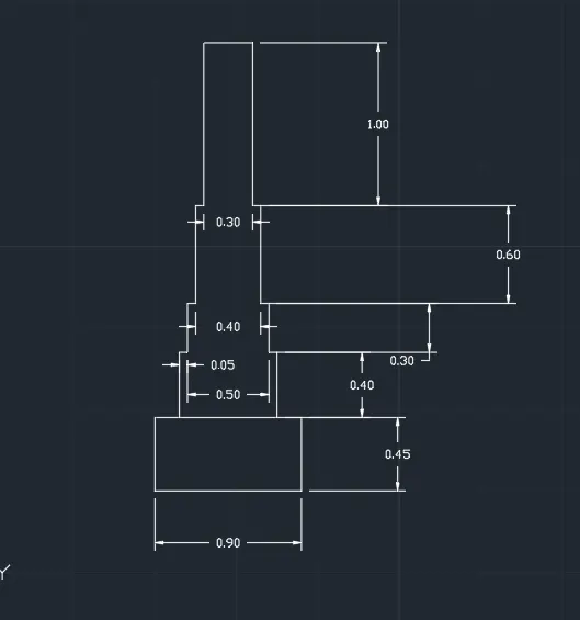
FIGURE 5
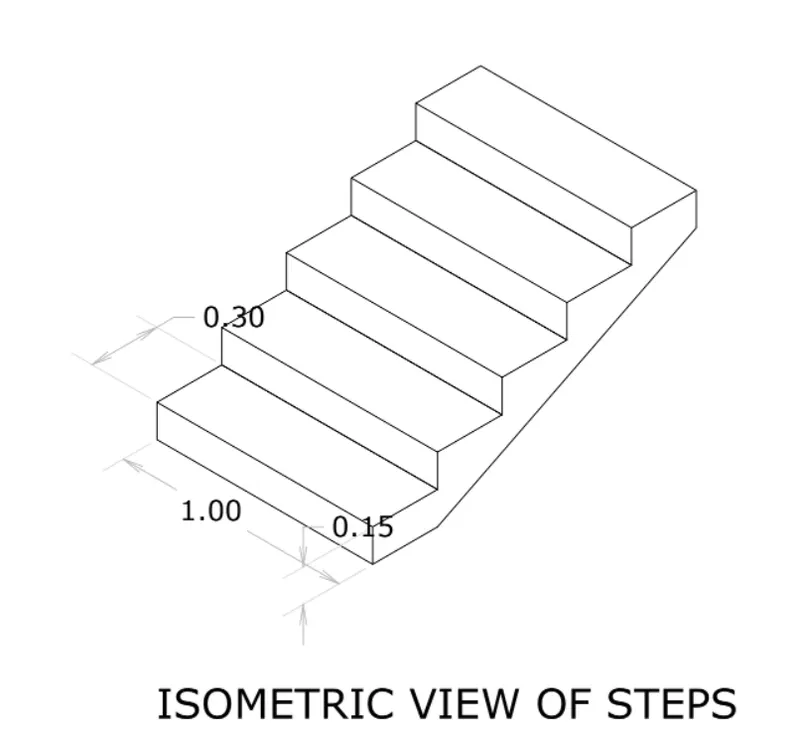
PROCEDURE
STEP1
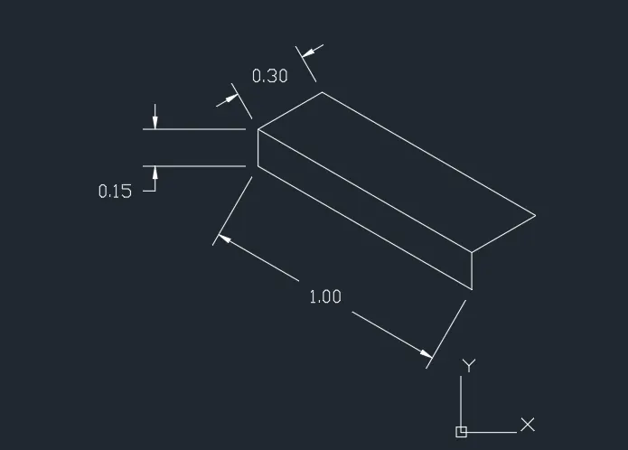
- To draw isometric view in the command bar type "ds" enter then off snap and grid and on isometric snap
- Make sure that ortho mode is on
- From isometric drafting select iso-plane left
- Select the line tool by entering LINE or L in the command tab
- Move the cursor -x direction left side and give 1
- move cursor to +y direction top and give o.15
- Move the cursor +x direction and give 1
- Move the cursor -y direction downwards and give 0.15
- press escape
- Change the isometric drafting to iso-plane top
- Select the line tool by entering LINE or L in the command tab
- Move the cursor to the back and give 0.3
- move the cursor to the right and give 1
- move the cursor to the front and give 0.3
STEP 2
- Change the isometric drafting to iso-plane Right
- Copy the object drawn and ortho off
- type "co"in the command bar and press enter
- specify the basepoint and copy it to the new point
- repeat the procedure until 4 steps are created
- Select the line tool by entering LINE or L in the command tab
- from the bottom step draw 0.3 towards right
- from the top step draw 0.15 downwards
- join them
FINAL RESULT
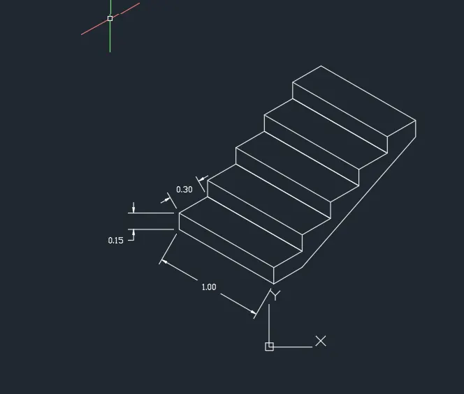
FIGURE 6
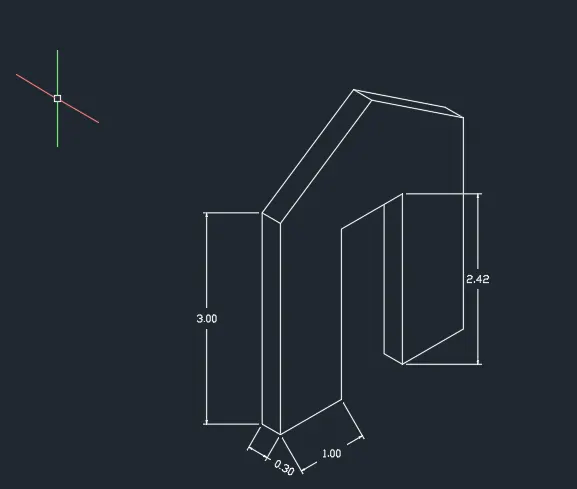
ISOMETRIC VIEW OF GABLE WALL
PROCEDURE
STEP1
- To draw isometric view in the command bar type "ds" enter then off snap and grid and on isometric snap
- Make sure that ortho mode is on
- from isometric drafting select iso-plane left
- Select the line tool by entering LINE or L in the command tab
- move the cursor to right give 1
- move the cursor towards up 3
- draw 0.3 to left and 3 downwards and o.3 left
- press escape
- Select the line tool by entering LINE or L in the command tab
- using isometric right draw a line upwards of 2.42
- move the cursor towards right 1 and 2.42 downwards
- press escape
- using isometric left again
- Select the line tool by entering LINE or L in the command tab
- draw 0.3 to left side and draw a line that intersects the top line
- press escape
- using isometric right
- Select the line tool by entering LINE or L in the command tab
- draw 1 to the right and 3 upwards
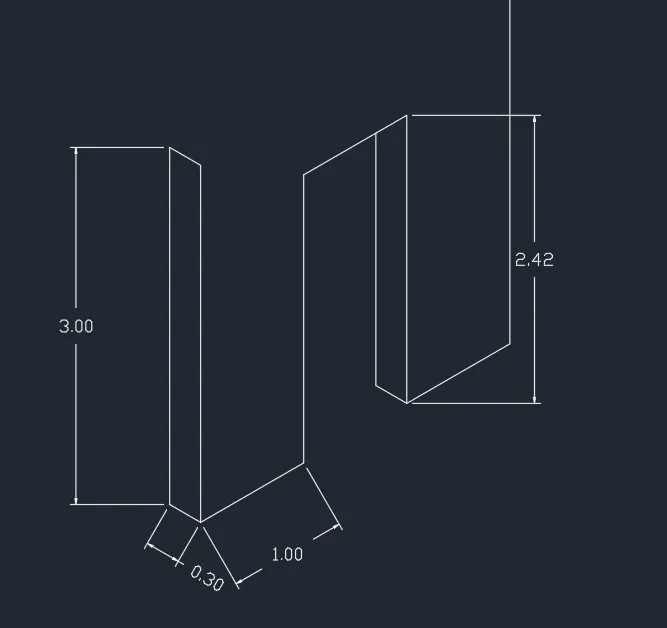
STEP 2
- using isometric right
- Select the line tool by entering LINE or L in the command tab
- draw a line from the bottom left corner 1.5 and draw upwards at 3.25
- with the ortho off draw a line between thecorner of left side and projected line same way in the right side
- draw a vertical line with ortho on o.3 and join the vertical line from the left and right
- delete the unwanted lines
FINAL RESULT
RESULT
Learned to draw floor plan, footing details and isometric views using modifying tools