Drafting of various geometries using Chamfer, Fillet tool in AutoCad
AIM
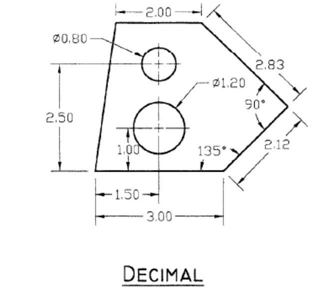
To draw the given sketch using autocad
FIGURE:1
PROCEDURE
STEP 1
- Select AutoCAD 2023 from the start menu
- In the command line type in:STARTUP then enter
- Enter the new value of startup:1
- Then from application menu select NEW
- 'Create New Drawing' dialog box will appear and from that select the Imperial System in the 'Start from the Scratch' option
- Next select the 'Decimal' unit system from the Advanced setup option
- set the limits by entering LIMITS in the command tab.lower left corner is specified as 0,0 and upper right corner is specified as 200,200
STEP 2
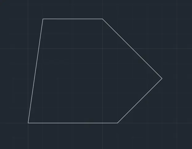
- using relative polar coordinate system
- Select line tool by entering 'LINE ' or 'L' command in the command tab
- Specify the first point as 5,5 in the command line
- Specify the next point as @3<0in the command line
- Specify the next point as @2.12<45in the command line
- Specify the next point as @2.83<135in the command line
- Specify the next point as @2<180 in the command line
- Type CLOSE OR C in the command line
STEP 3
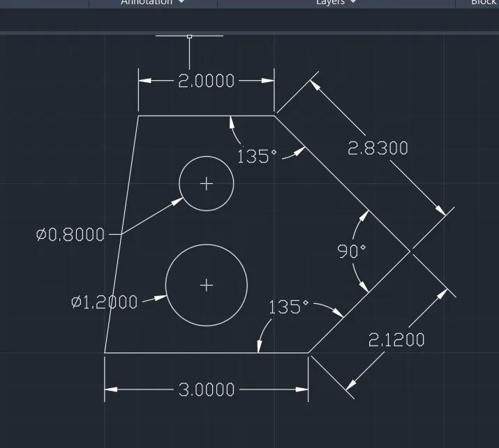
- By using offset command in the command bar 'O' enter
- Offset 3.00 line to 1.00 and 2.50
- By using circle command in the command bar 'c' enter
- From the midpoint of 3.00 line draw circle
- At 1.00 line draw a circle of diameter 1.20
- At 2.50 line draw a circle of diameter 0.80
- Then erase the offsets
FINAL RESULT
AIM
To draw the given sketch using autocad
FIGURE : 2
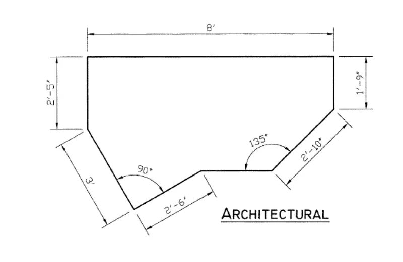
PROCEDURE
- Open a new file
- In the command line type units , select architectural
- Keep the polar tracking on
- Select line tool by entering 'LINE ' or 'L' command in the command tab
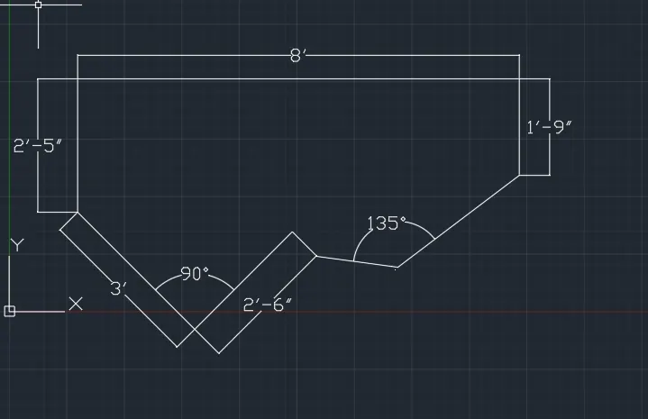
- Draw a horizontal line and draw 2'6"line at 225 degree
- Draw 3'line perpendicular to above line
- Above that draw a vertical line 2'5" and 8' horizontal line
- Then draw 1'9" vertical line and 2'10"line at 225 degree and close
FINAL RESULT
AIM
To draw the given sketch using autocad
FIGURE:3
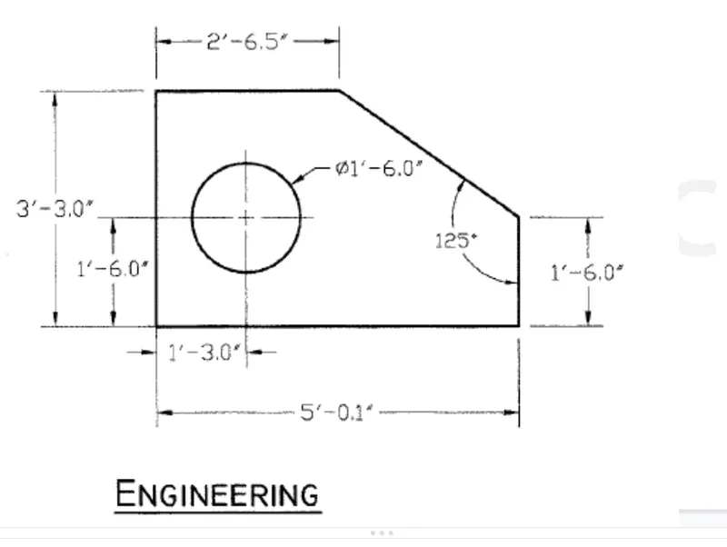
PROCEDURE
- Open a new file
- In the command line type units , select engineering
- Select line tool by entering 'LINE ' or 'L' command in the command tab
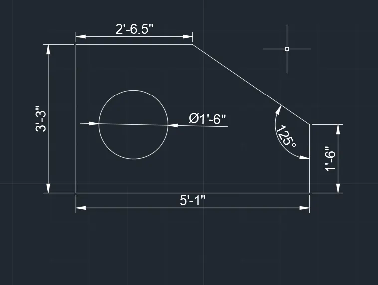
- Enter the length of point 1 as 2'-6.5"in the command line towards -ve x-axis
- Enter the length of point 2 as 3'-3.0" in the command line towards -ve y-axis
- Enter the length of point 3 as 5'-01" in the command line towards +ve x-axis
- Enter the length of point 4 as 1'-6.0" in the command line towards +ve y-axis
- Close
- Select offset tool by entering 'OFFSET ' or 'O' command in the command tab
- Offset 3'-3.0"line at a distance of 1'-3.0"and 5'-01" at a distance of 1'-6.0"
- Select circle tool by entering 'CIRCLE ' or 'C' command in the command tab
- Draw a circle of diameter of 1'-6.0" from the center of offsetted lines
- Erase the offsetted lines using erase command
FINAL RESULT
AIM
To draw the given sketch using autocad
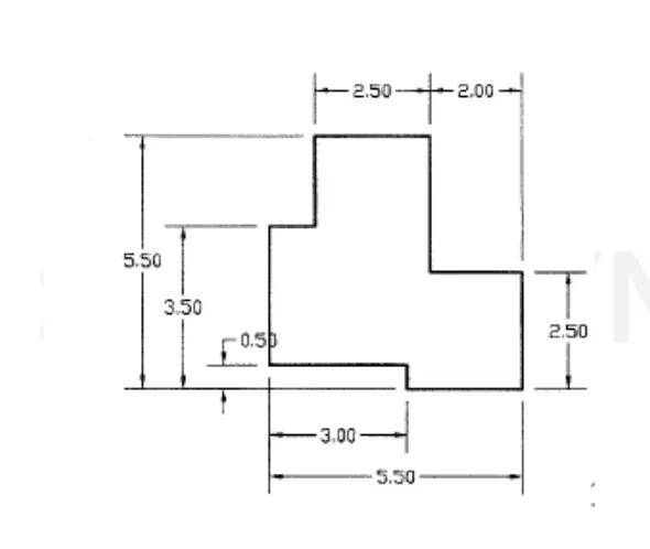
FIGURE :4
PROCEDURE
- Open a new file
- In the command line type units , select decimal
- Select line tool by entering 'LINE ' or 'L' command in the command tab
- Specify the first point as 5,5 in the command line
- Enter the length of point 2 as 3 in the command line towards +ve x-axis
- Enter the length of point 3 as 0.50 in the command line towards -ve y-axis
- Enter the length of point 4 as 2.50 in the command line towards +ve x-axis
- Enter the length of point 5 as 2.50 in the command line towards +ve y-axis
- Enter the length of point 6 as 2in the command line towards -ve x-axis
- Enter the length of point 7 as 3 in the command line towards +ve y-axis
- Enter the length of point 8 as 2.5in the command line towards -ve x-axis
- Enter the length of point 9 as 2 in the command line towards -ve y-axis
- Enter the length of point 10 as 1 in the command line towards -ve x-axis
- Enter the length of point 11 as 3 in the command line towards -ve y-axis
- press ESCAPE in the command line
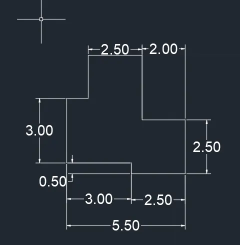
FINAL RESULT
AIM
To draw the given sketch using autocad
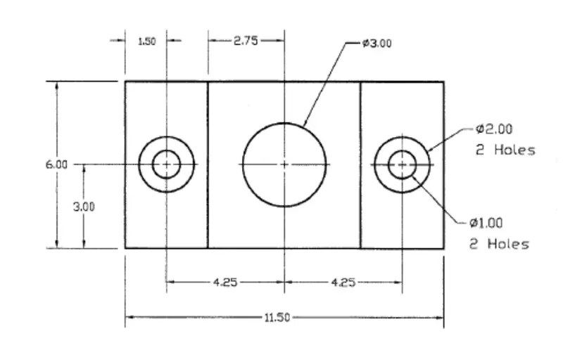
FIGURE: 5
PROCEDURE
- Open a new file
- In the command line type units , select decimal
- Select line tool by entering 'LINE ' or 'L' command in the command tab
- Draw 6 vertical , 11.50 horizontal and 6 vertical and 11.50 horizontal
- press escape
- In object snap setting keep midpoint , center , geometric centre and intersection on
- Select offset tool by entering 'OFFSET ' or 'O' command in the command tab
- Offset 6.00 line at a distance 1.50,3,5.75,8.50,10 and offset 11.50 line at a distance of 3.00
- Select circle tool by entering 'CIRCLE ' or 'C' command in the command tab
- Draw concentric circles at the intersection of offsetted line of diameter 1.00 and 2.00 and draw a circle at center with diameter 3.00
- Using erase command erase unwanted offsetted lines
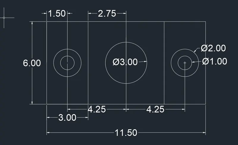
FINAL RESULT
AIM
To draw the given sketch using autocad
FIGURE :6
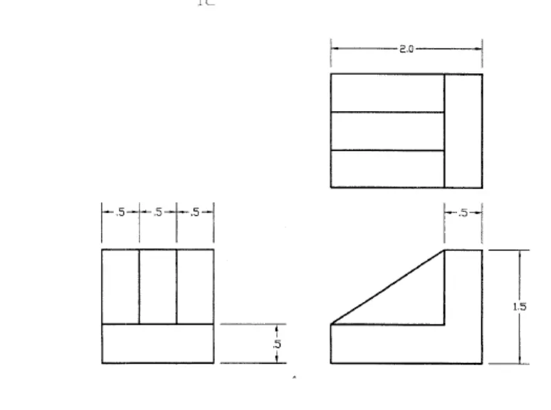
PROCEDURE
- Open a new file
- In the command line type units , select decimal
- Select line tool by entering 'LINE ' or 'L' command in the command tab
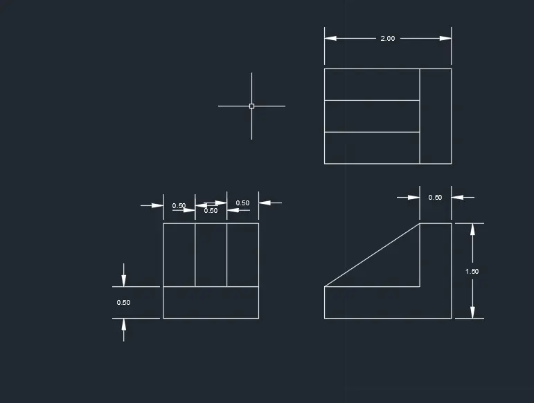
- Draw 1.5 horizontal , 1.5 vertical repeat and form a square
- Select offset tool by entering 'OFFSET ' or 'O' command in the command tab
- Offset 1.5 bottom line one time at a distance of 0.5 and offset from side 1.5 line at a distance of 0.5 for two times
- Trim the unwanted portions
- In object snap setting keep the extension on
- Select line tool by entering 'LINE ' or 'L' command in the command tab
- Draw 2.0 horizontal line in +ve x direction and 1.5 vertical line in +ve y direction and 0.5 horizontal line in -ve x direction and 1.5 down in -ve y direction and 1.5 in horizontal line in - ve x direction and 0.5 vertically downwads in -ve y direction
- Join the slant height
- Select line tool by entering 'LINE ' or 'L' command in the command tab
- Draw 2.0 horizonal and 1.5 vertical on both sides
- Select offset tool by entering 'OFFSET ' or 'O' command in the command tab
- offset 2.0 line at a distance of 0.5 for 2 times and 1.5 line from right side at a distance of 0.5 for 1time
- Trim the unwanted portions
FINAL RESULT
AIM
To draw the given sketch using autocad
FIGURE :7
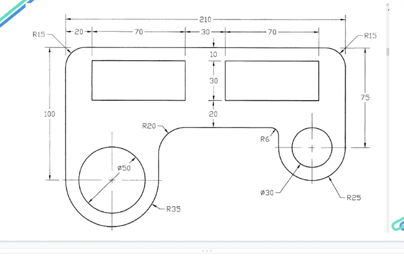
PROCEDURE
- Open a new file
- In the command line type units , select decimal
- Select line tool by entering 'LINE ' or 'L' command in the command tab
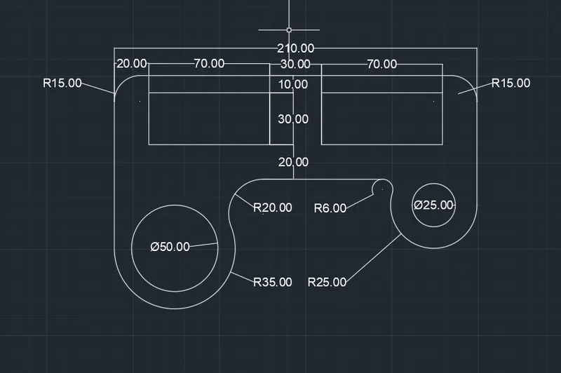
- Draw 210 horizontal line and 100 vertical line on left side and 75 vertical line on right side, since arc has radius of 35 drawing aline of 70 on left side and in right side having arc of radius 25 so drawing line of 50 on right side
- Select arc tool using start , end and radius , draw an arc of radius 35 on left side and radius 25 arc on right side
- Select circle tool by entering 'CIRCLE ' or 'C' command in the command tab
- Draw circle of diameter 50 on the mid point of the 70 line and another circle of diameter 30 on the 50 line
- Select offset tool by entering 'OFFSET ' or 'O' command in the command tab
- Offset the 210 line at a distance of 60
- Select the fillet command
- Fillet by radius 15 on top right and left and radius of 20 on inner left and radius of 6 on inner right
- Select offset tool by entering 'OFFSET ' or 'O' command in the command tab
- Offsetting 210 line at a distane of 10 and 100 line at a distance of 20 and 75 line at a distance of 20
- By using rectangle command draw a rectangle of 70 length and 30 width from the offsetted lines on the both sides
- Using erasing command erase the unwanted offsetted lines
FINAL RESULT
AIM
To draw the given sketch using autocad
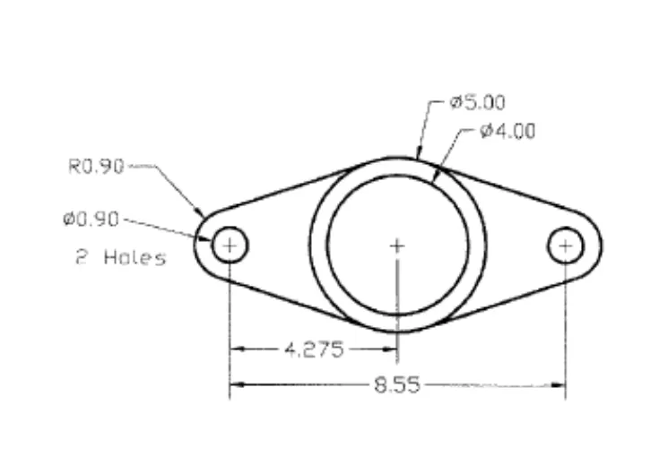
FIGURE:8
PROCEDURE
- Open a new file
- In the command line type units , select decimal
- Select line tool by entering 'LINE ' or 'L' command in the command tab
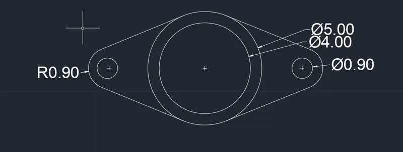
- Draw a line of 8.550
- Select circle tool by entering 'CIRCLE ' or 'C' command in the command tab
- In the midpoint of the line draw concentric circles of diameter 5 and 4
- At both the end of the line draw circle of diameter 0.90
- Using arc command , start, end and radius draw an arc of radius 0.90 on both sides
- Select line tool by entering 'LINE ' or 'L' command in the command tab
- keeping the object snap on with tangent
- conncet line to the arc
FINAL RESULT
AIM
To draw the given sketch using autocad
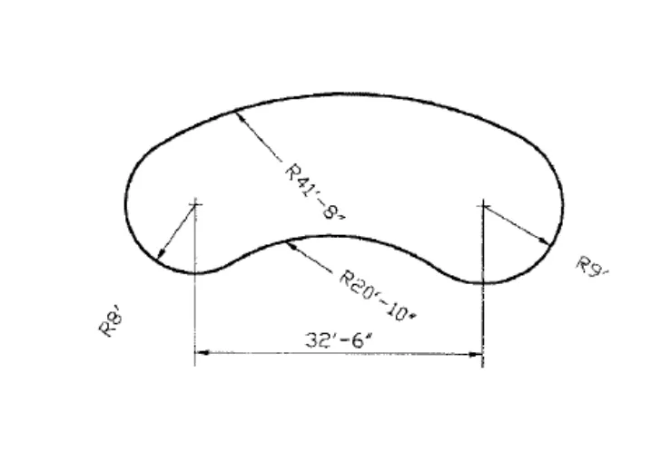
FIGURE :9
PROCEDURE
- Open a new file
- In the command line type units , select engineering
- Select line tool by entering 'LINE ' or 'L' command in the command tab
- Draw a 32'-6" horizontal line
- Select circle tool by entering 'CIRCLE ' or 'C' command in the command tab
- Draw a circle of radius 8' on left side of the line and radius 9' on the right side of the line
- Using arc command from start, end and radius drawing an arc of 41'-8" on top and 20'-10" on bottom
- Using trim command trim the unwanted lines and curves
FINAL RESULT
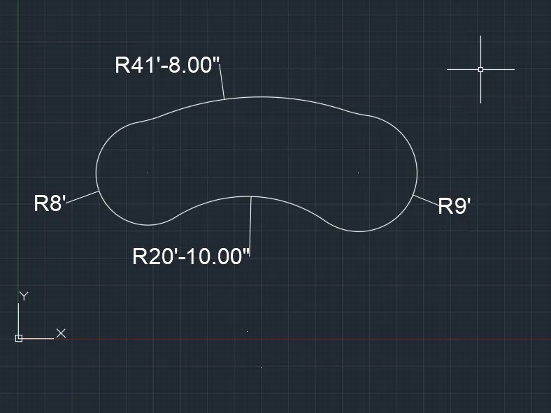
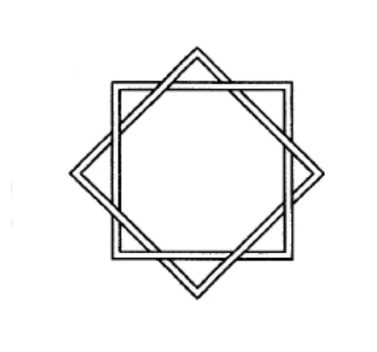
FIGURE :10
PROCEDURE
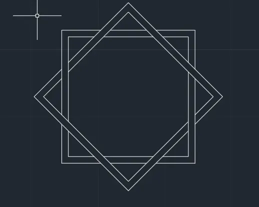
- Creating a rectangle, in the command box REC enter
- Draw 2 rectangle of same length and width of one smaller and the another one slightly bigger with common center
- Using rotate command rotate the rectangles by 45 degree by keeping the copy
- Using the trim command trim the unwanted lines
FINAL RESULT
AIM
To draw the given sketch using autocad
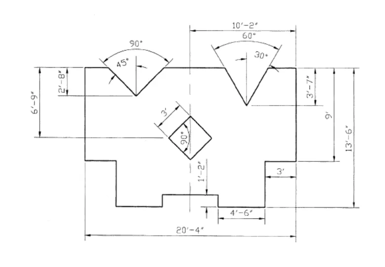
FIGURE :11
PROCEDURE
- Open a new file
- In the command line type units , select engineering
- Select line tool by entering 'LINE ' or 'L' command in the command tab
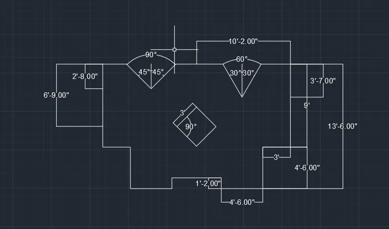
- Draw10'-2" horizontal line , 9' vertical line and 3'horizontal line ,4'-6"vertical and horizontal line and 1'-2" vertical line
- Using mirror command mirror the above lines with respect to the central axsis
- Select offset tool by entering 'OFFSET ' or 'O' command in the command tab
- offset the 20'-4" to a distance of 6'-9" and 13'-6" to a distance of 10'-2"
- Using rectangle command draw a rectangle of 3' length and width at the centre point of offsetted line
- using move command move the center of rectangle to center of offsetted line
- Using the rotate command rotate the rectangle by 45 degrees
- Select offset tool by entering 'OFFSET ' or 'O' command in the command tab
- offsetting 20'-4" to a distance of 2'-8" with polar tracking on draw an angle of 90 degrees.offset 20'-4" to a distance of 3'-7" with polar tracking on draw an angle of 60 degrees
- using erase command erase the unwanted lines
FINAL RESULT