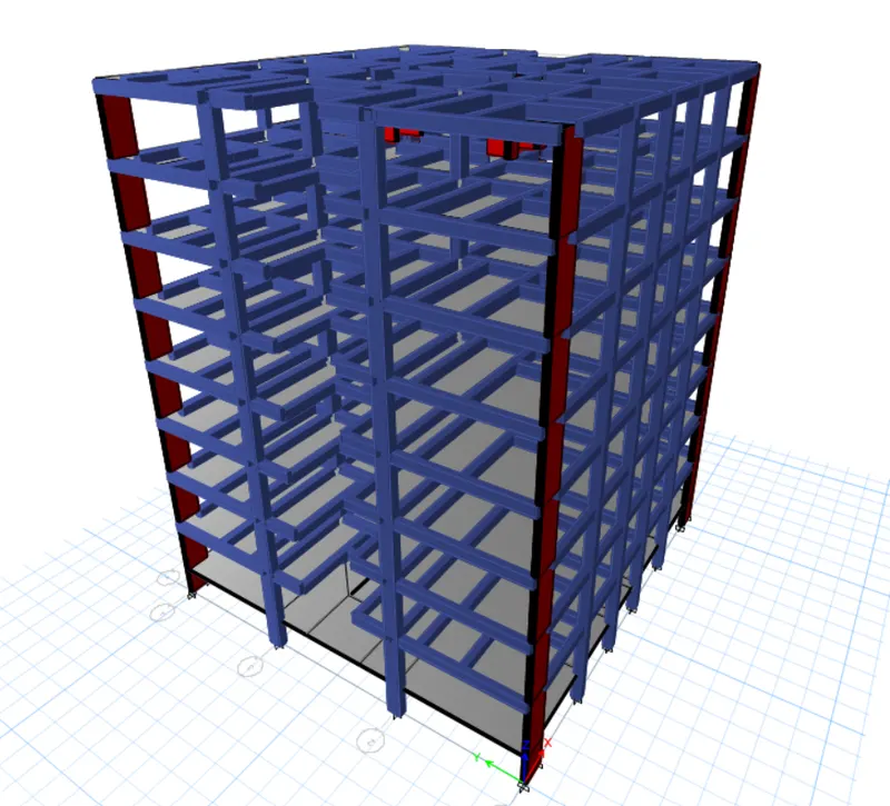
Structural Modelling using Etabs 2018
AIM: The architectural drawings for a G+7 residential building in zone 5 has been provided. The floor plan is the same for all 7 floor levels. Possible column positions have also been provided. Conceptualize a framing plan layout and then model the building in Etabs. The following architectural drawings have been provided:
- Typical floor plan – The location and thickness of the brick walls and the use of the
space (for estimating live load) can be obtained from this plan - A building section through the staircase and lift core is provided
- Parking layout in the ground floor – the column/shear wall arrangement must not
obstruct entry/exit of vehicles.
The following loadings are to be taken into account: - Brickwall made of AAC blocks
- Finishes – floor tiles of 75 mm thickness
- Live loads as per IS 875 part 2
- Water tank of 20 KL above the staircase at Mumty level
- Lift Machine room at mumty level above lift core
The structural model must comply with provisions of IS 1893 and IS 13920.
Run a modal response spectrum analysis and check analysis results of the etabs model for inter-storey drift requirements, vertical & planar irregularities, minimum shear wall requirements,maximum axial load ratio for column and shear walls, effective moment of inertia for beams
and columns etc.
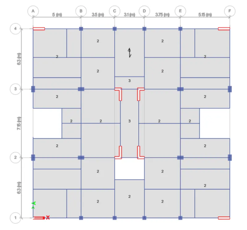
Please note that the column positions shown in the architectural typical floor plan are only to provide an initial starting point for modelling. Participants will have to change its size, introduce shear walls, and add new vertical elements after running the analysis. You will have to run the analysis multiple times until a structural model is obtained that meets structural code requirements without compromising architectural functions. Also, there is no one ‘correct’ structural system for this challenge. There can be multiple possible solutions for this problem.
INTRODUCTION: ETABS is an engineering software product that caters to multi-story building analysis and design. Modeling tools and templates, code-based load prescriptions, analysis methods and solution techniques, all coordinate with the grid-like geometry unique to this class of structure.
PROCEDURE:
1. Open the ETABS softwar by double click on that icon, sofware interface opens as shown below.
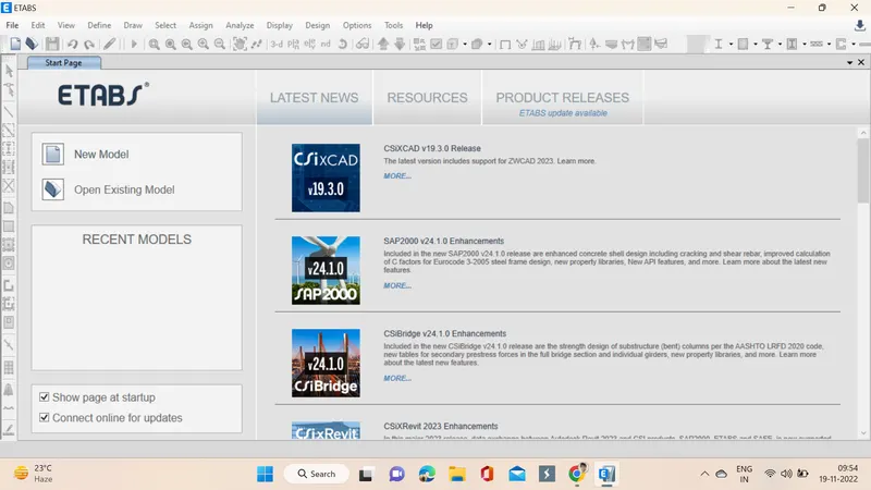
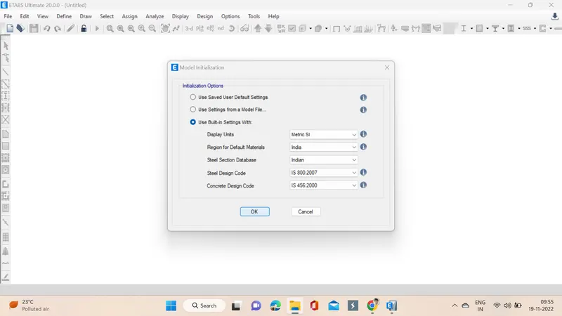
2. The very next step is to assign settings like codes used and units, then ok is clicked.
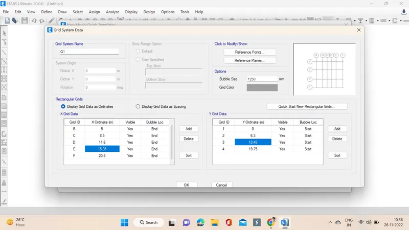
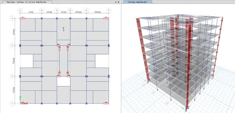
3. Now another tab pops up in which custom gird spacing is selected and edit grid data is opened. First select the custom grid and change the grid as per the plan given.
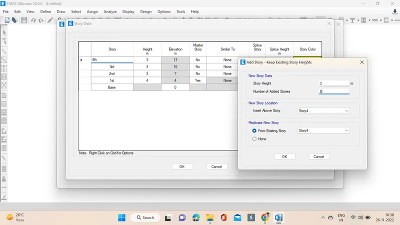
4. Next step we click on edit story data and then we change story 1 as plinth and then we specify the plinth height as 1.5 and change the names of stories accordingly, next we right click to add the next stories as challenge G+7 we select 5 more in no of stories to be added since already 3 stories are present.
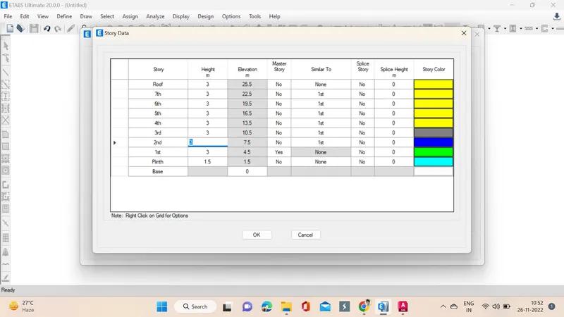
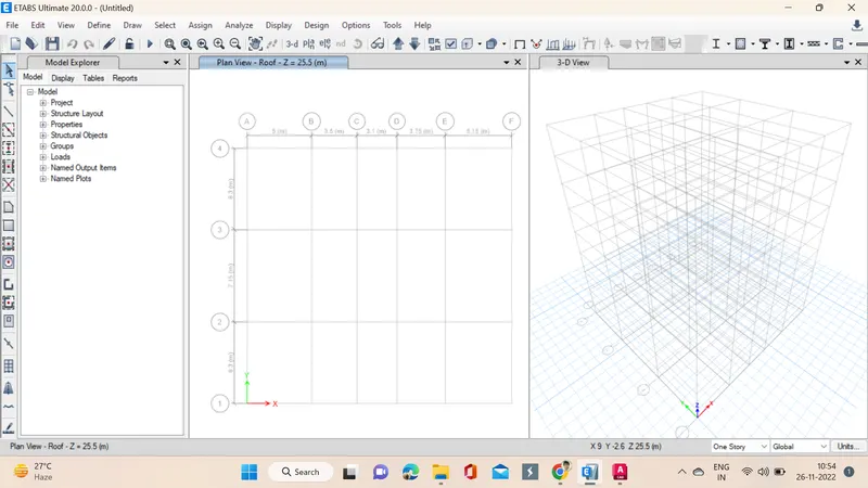
5. So, successfully G+7 stories added as per the challenge.
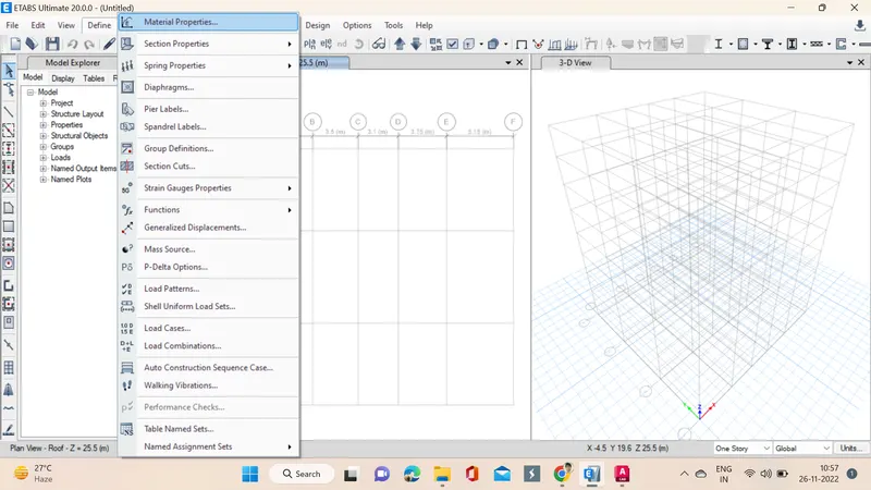
6. Go to define materials option, select material properties, in that concrete of M25 & M30 and reinforcement of HYSD415 & HYSD500 are added.
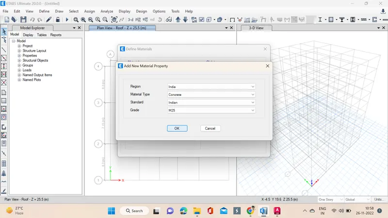
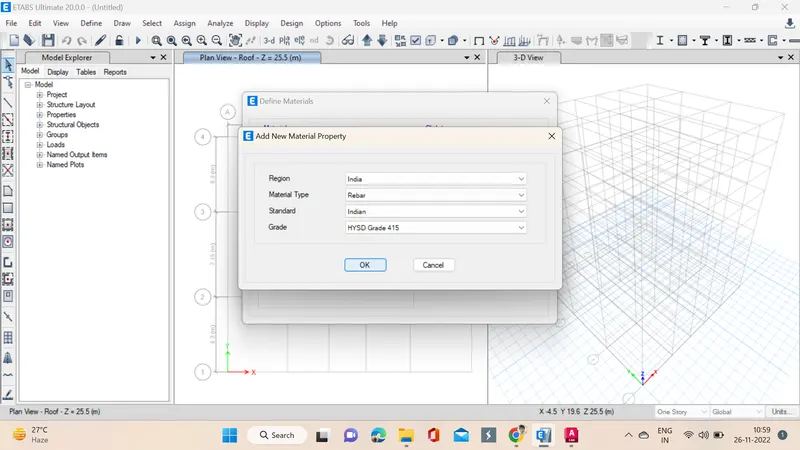
7. We need assign beams, columns, slabs for that go to define option select frame sections. Beams as per the schedule is titled and dimensions are also specified, in the section properties beam is selected and material M30 and rebars of HYSD415, HYSD500 beams of sizes 250x450, 300x500.
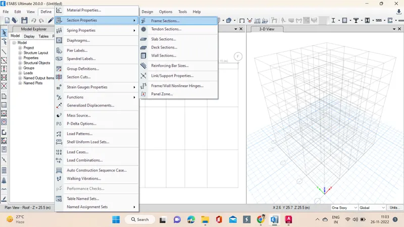
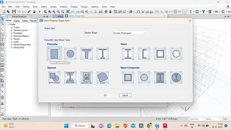
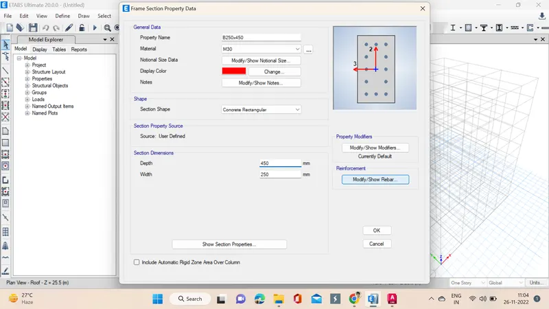
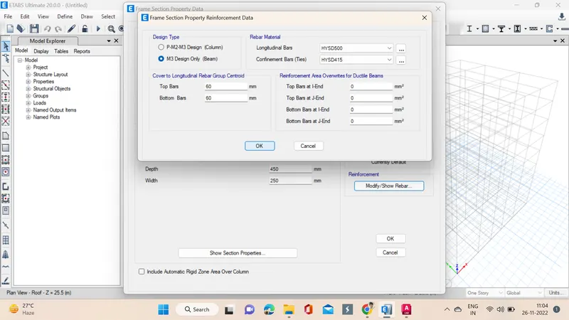
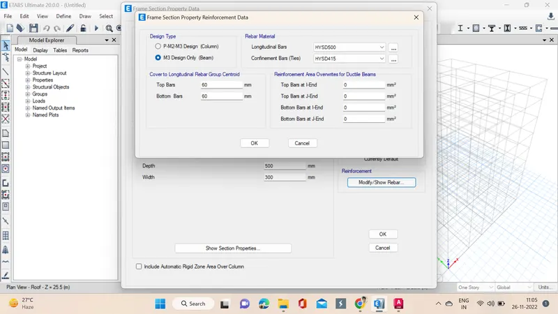
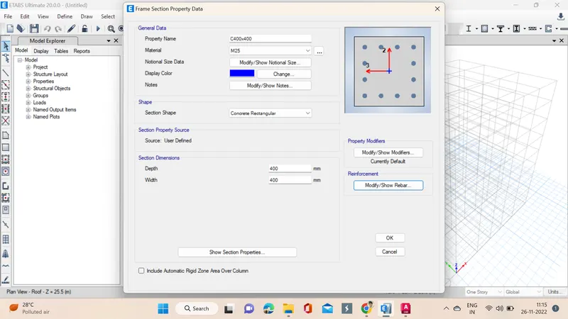
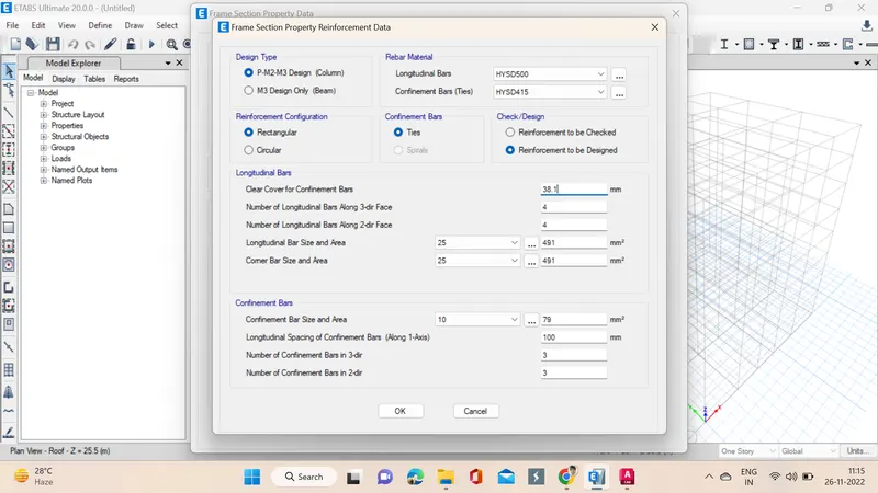
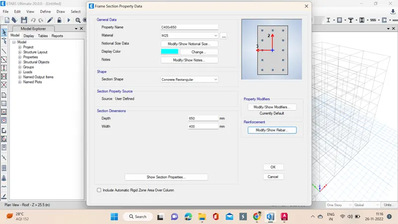
8. The process is same for columns assigning materials and dimensiopns but section properties column is selected that is the only change. In the section properties column is selected and material M25 and rebars of HYSD415, HYSD500 columns of sizes 400x400, 400x650.
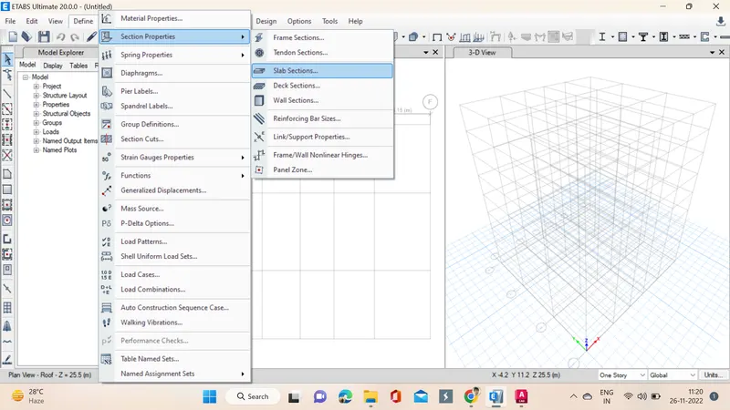
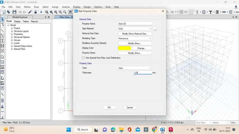
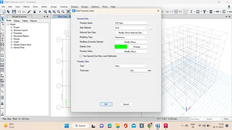
9. Next step we go through the define material and then select slab sections a window pops up in which we specify the properties of the slab and it is attached to the membrane. Slab of 125mm is created with concrete M25 and STR Slab of 200m thickness with concrete M25.
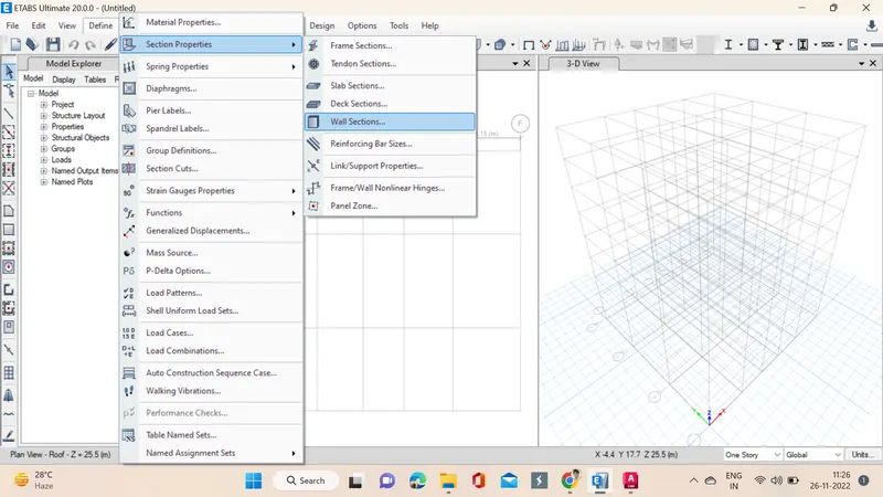
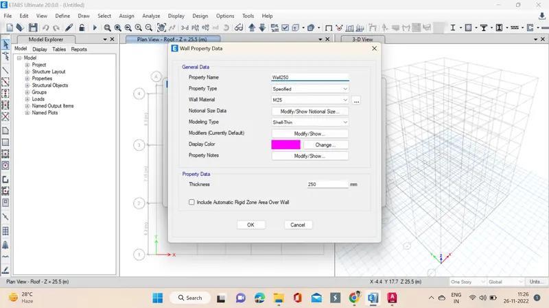
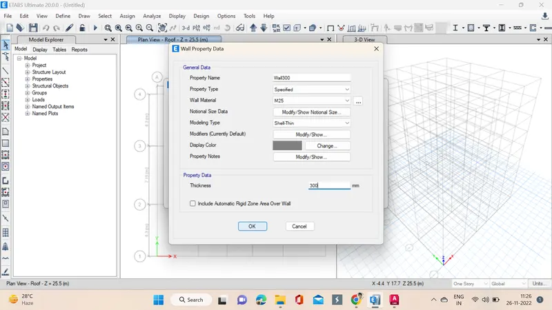
10. Next step we go through the define material and then select wall sections a window pops up in which we specify the properties of the wall, with dimensions of 250mm & 300mm is created with concrete M25.
11. Now by selecting quick column and properties of specified column the columns are placed but we need to make sure the all stories option is selected. We can see the columns are specifed in all the stories, as we opted all stories option in the bottom right side. Next we use replicate option to simply replicate all the columns as first to save time. Top and Bottom columns of C400x400 are placed, next the other columns of C400x650 are placed and also they are oriented as per requirement for the design.
To orient them we need to select them first then Go to Assign -> Frame -> Local Axes -> change to rotate and mention angle as 90 degrees.
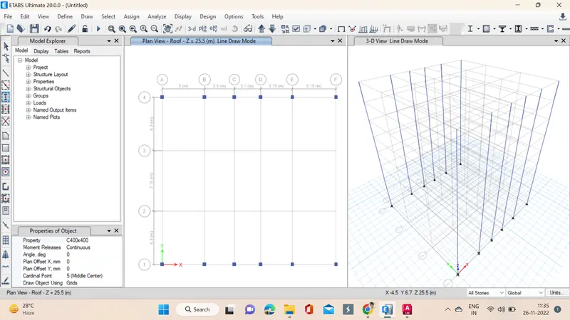
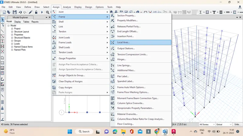
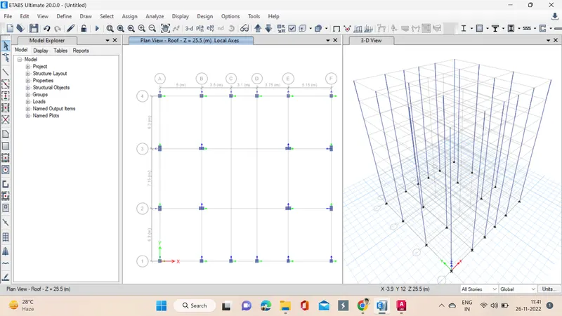
12. Now by selecting quick beams and properties of specified beams the beams are placed but we need to make sure the all stories option is selected. We can see the beams are specifed in all the stories, as we opted all stories option in the bottom right side. Next we use replicate option to simply replicate all the columns as first to save time. Secondary beams are added using ctrl+m and ctrl+r options.
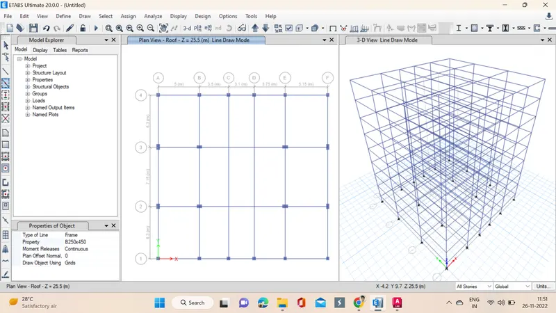
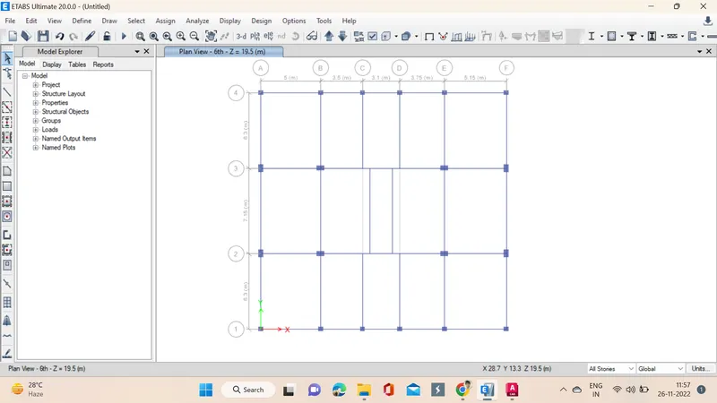
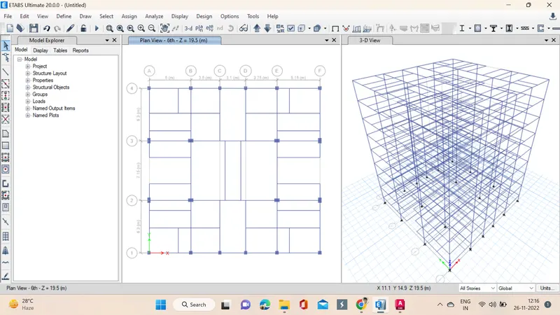
13. Now we add shear walls in the required locations.
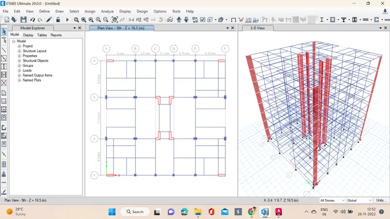
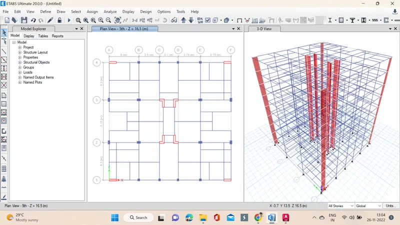
14. Now the slabs are placed by selecting quick draw slab, we need to select the specified slab and then drop them in the stories.
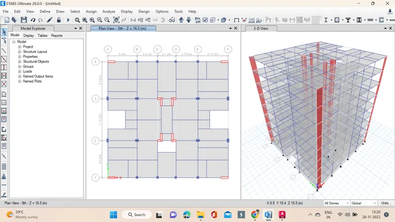
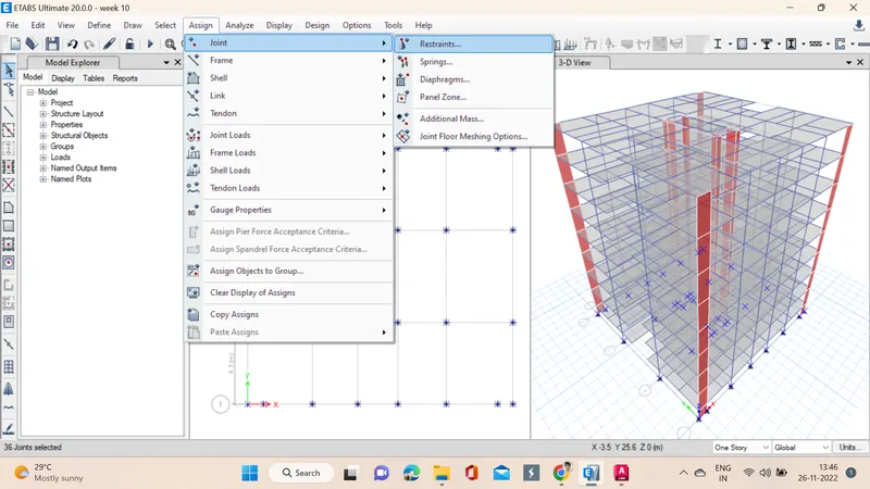
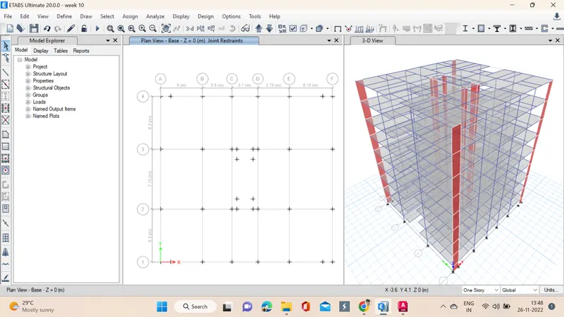
15. Now we go to base plan and select all the joints. Now we select the Restraint from joint option, as shown below.
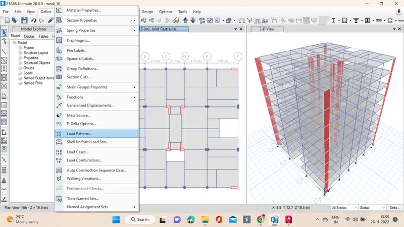
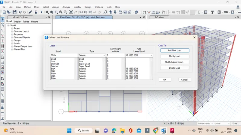
16. Now define the Load patterns for that click on the define tab and click on load patterns. Define the loads like dead load, live load, brick load, earthquake load in X direction and same loads in Y direction also. Mention IS codes of respective loads.
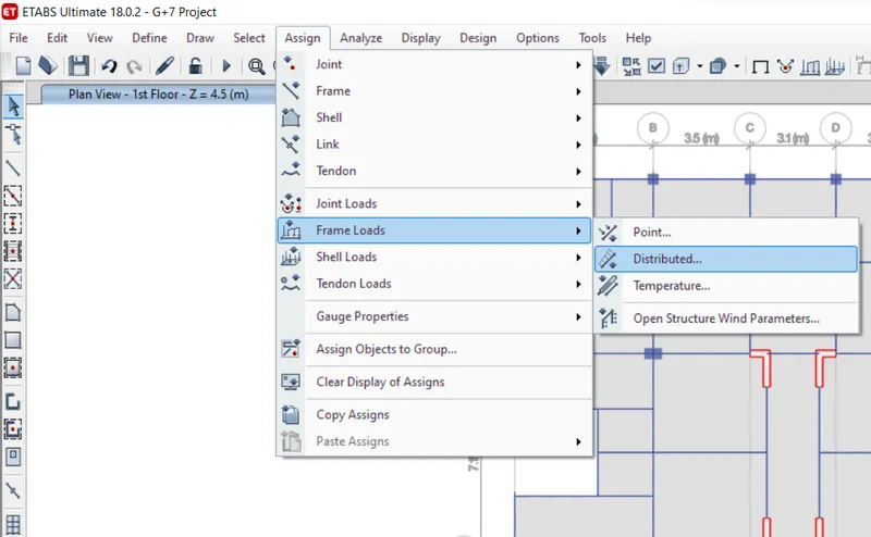
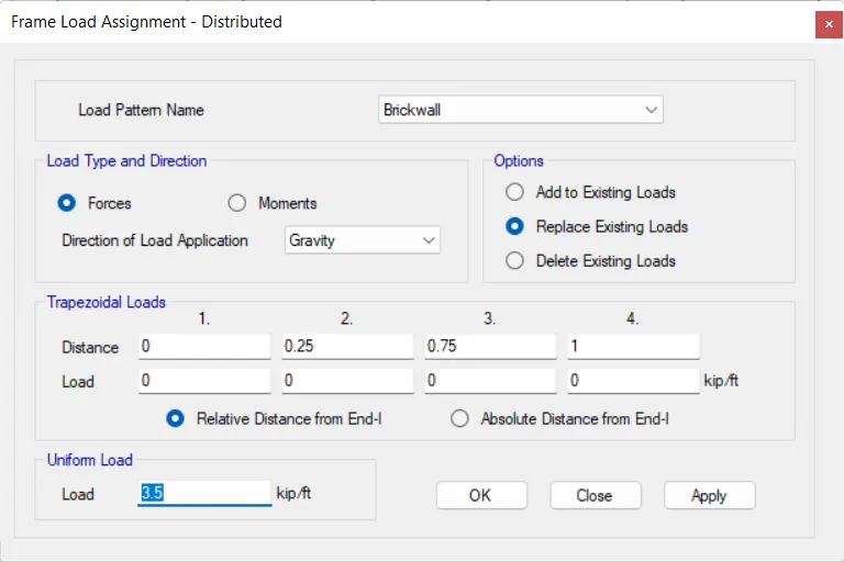
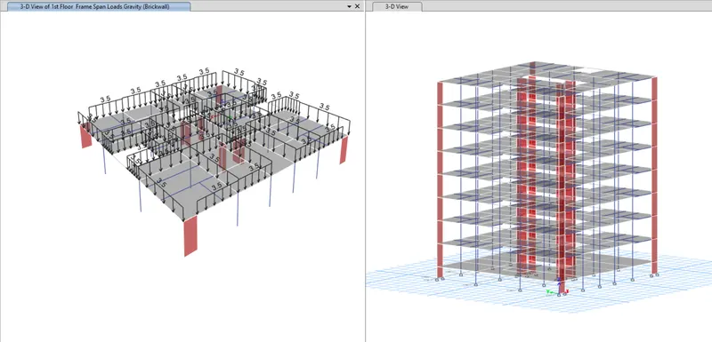
17. Now we will apply loads, for that first we select the beams from select option -> properties -> frame sections, after selecting the beams now load is assigned by going into assign option assign -> frame loads -> distributed in the distributed a window pops up in which load pattern Brickwall and we take uniform load as 3.5 Kn/m an then apply for similar stories.
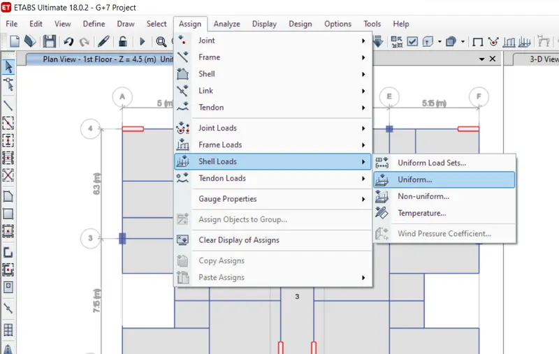
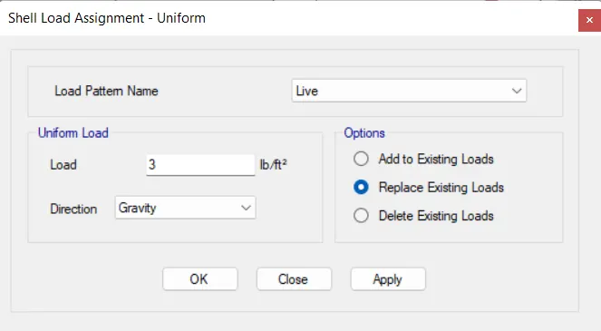
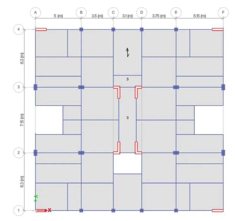
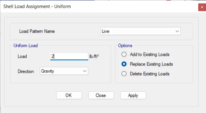
18. Next we have to click on assign option and then select shell loads and select uniform option. Here we apply 3 Kn/m2 live load for the staircase portion, verandah and lift core area. Here we apply 3 Kn/m2 live load for the staircase portion, verandah and liftcore area.
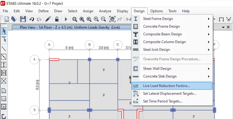
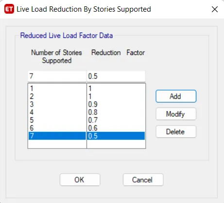
19. Next we add live load reduction factor for that we Go to Design -> Live Load Reduction Factors. Now we add the reduction factor as decrease of 10% from 1st to 7th floor.
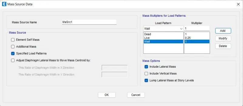
20. Now go to Mass Source from define tab. Modify the mass source and tick mark the required loads. Add load patterns and assign the model. Insert the dead load as multiplier to 1, live load as multiplier to 0.25 and wall load as multiplier to 1.
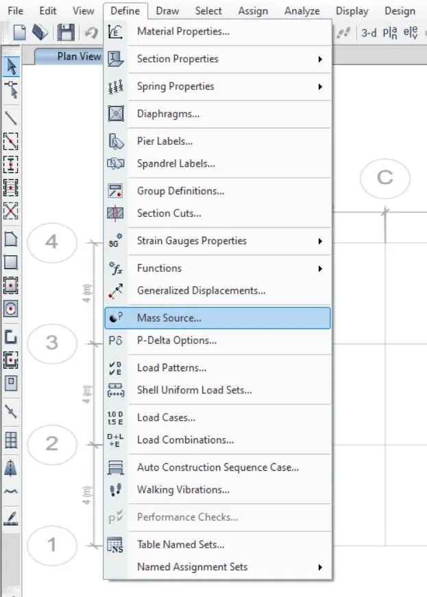
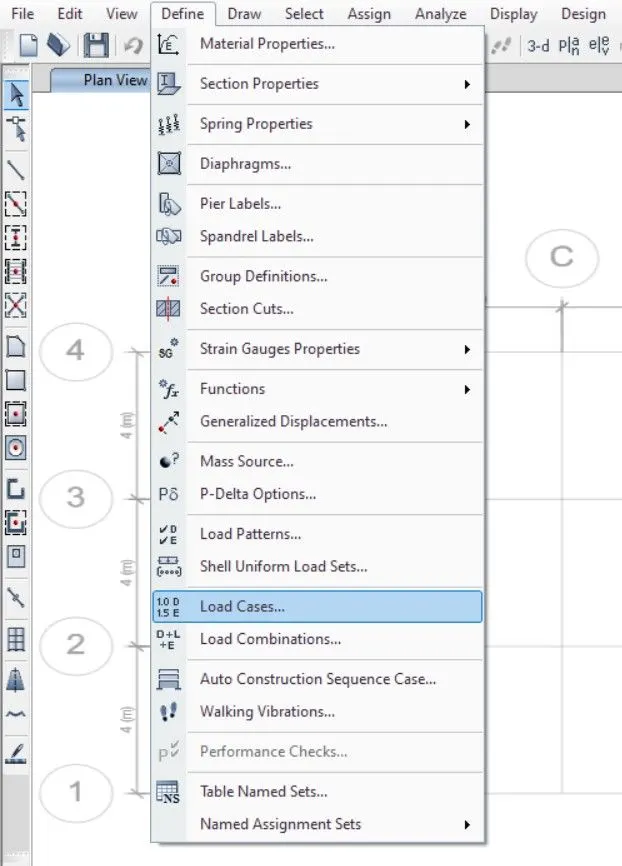
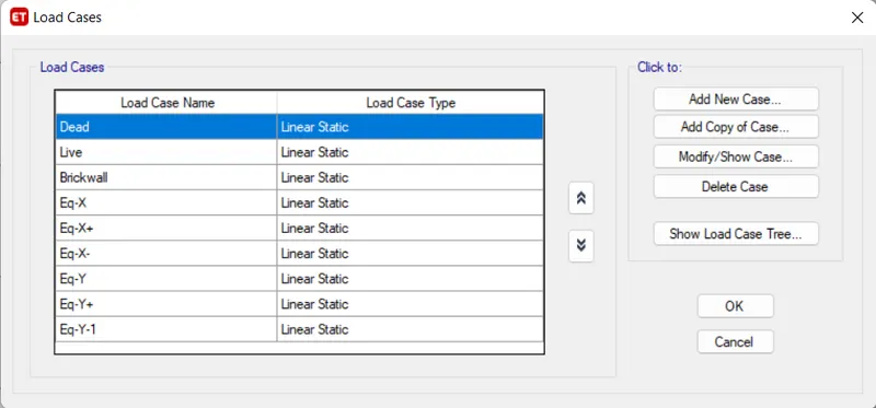
21. Now to specify load cases Go to Define -> Load Cases.
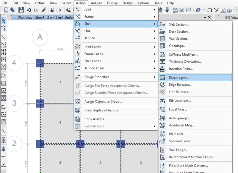
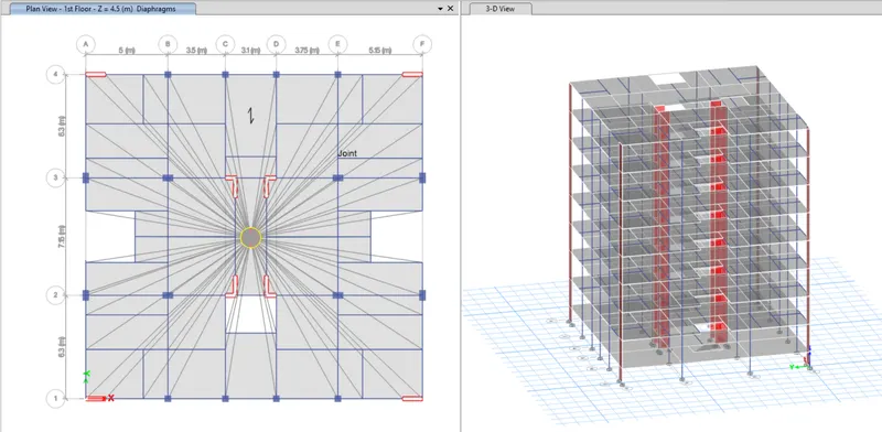
22. Again slabs are selected this time to assign diaphragms and then D1 is assigned so that the centre of mass will be calculated automatically.
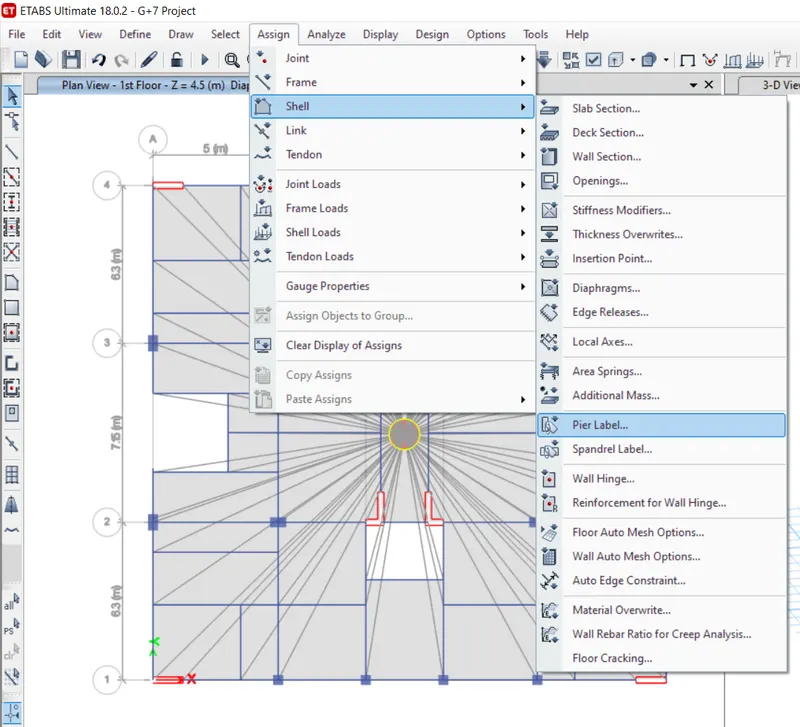
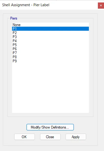
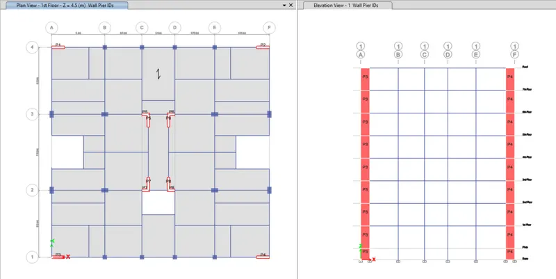
23. Next we have to select the pier lable from shell option. Now we have to assign the names for the shear wall.
24. Now load cases are added or not checked by clicking on load cases, next load combinations are specified by selecting frame design user defined in load combinations.
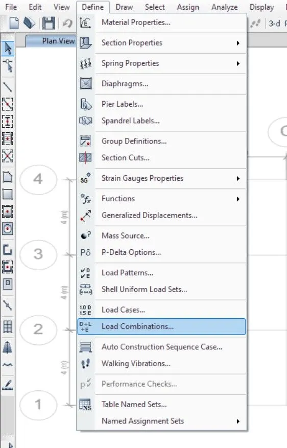
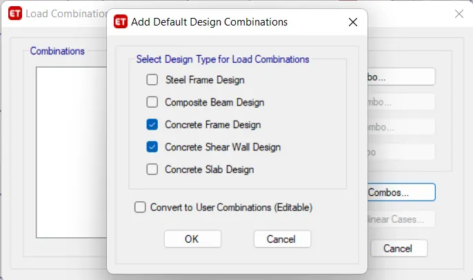
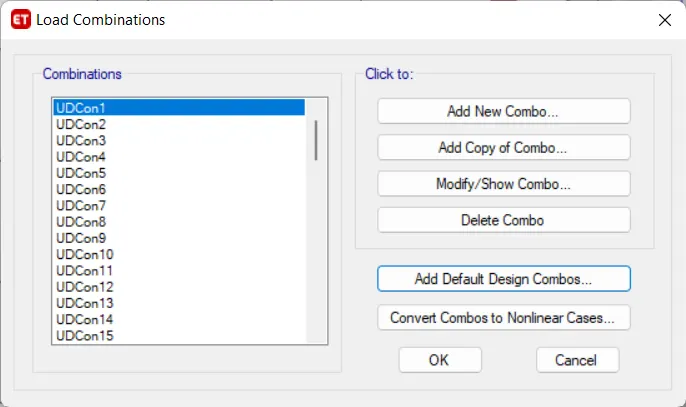
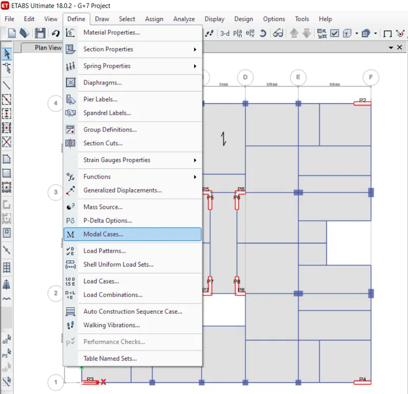
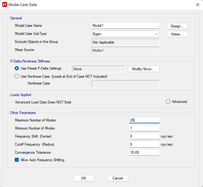
25. Next we add model cases from define option. Give ideal case name as Model1 and we give the maximun number of modes as 20.
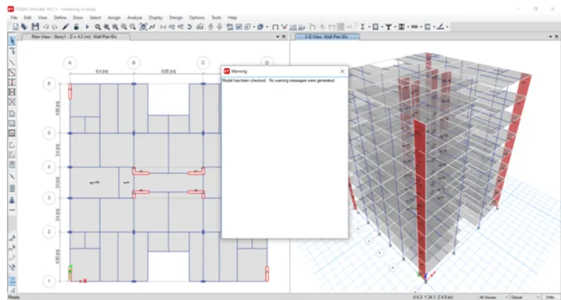
26. Next we need to check the Model. After the model is checked, it will show us No warning.
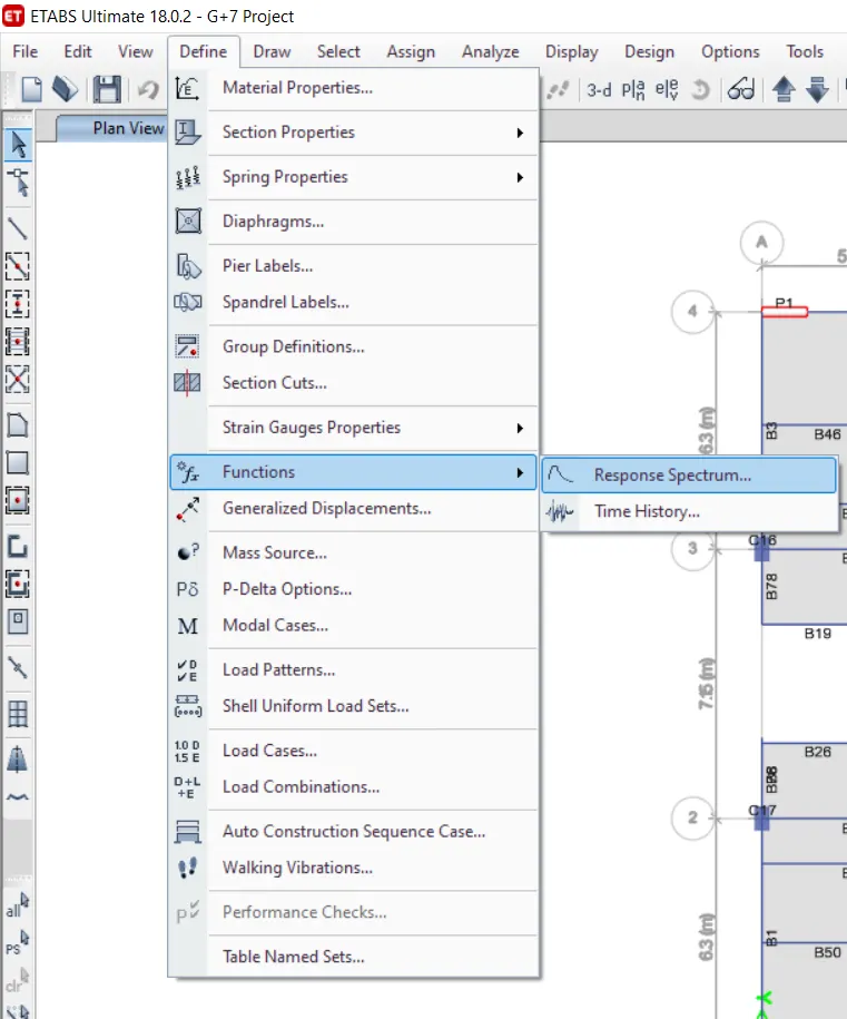
27. Now select the response spectrum from Functions option in define Tab. We choose IS 1893:2016 from choose function Type and click on Modify/Show spectrum option.
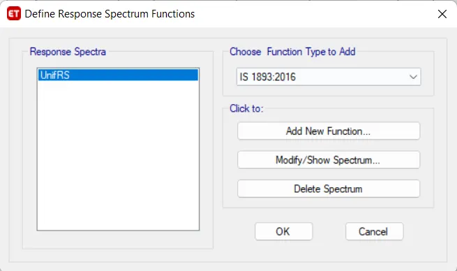
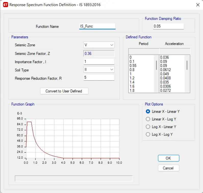
28. Now go to Load cases in define Tab.
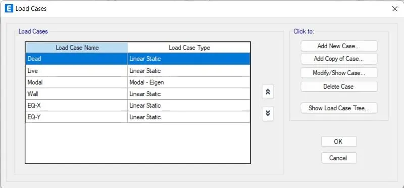
29. Add new case for the model as Rsx for Response Spectrum.
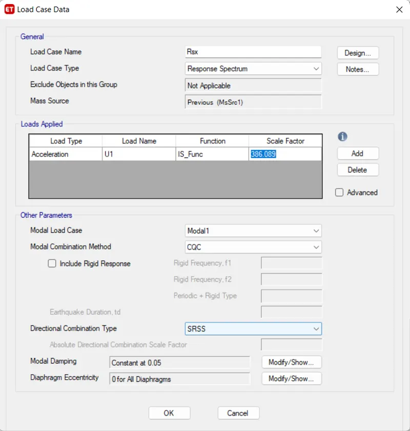
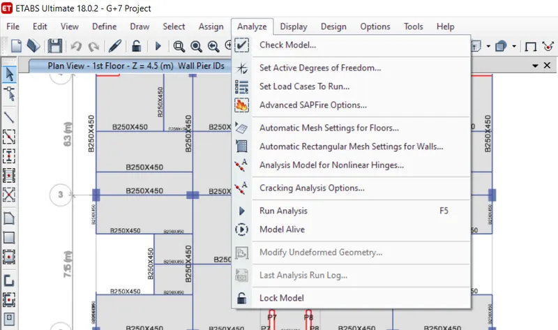
30. Analyse the model using analyse option then click on check model the modelled structure is verified without errors and warnings.

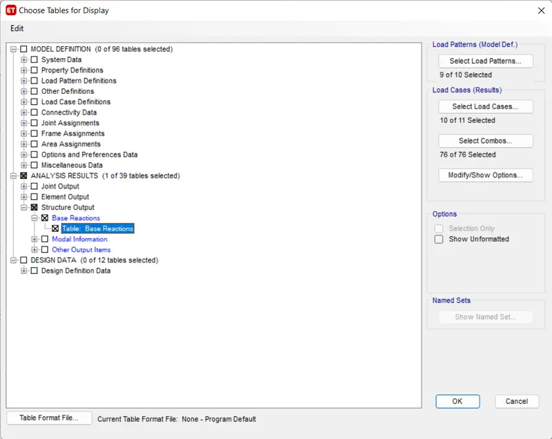
31. Now click on display -> show tables -> Analysis result structure output -> Base Reactions.
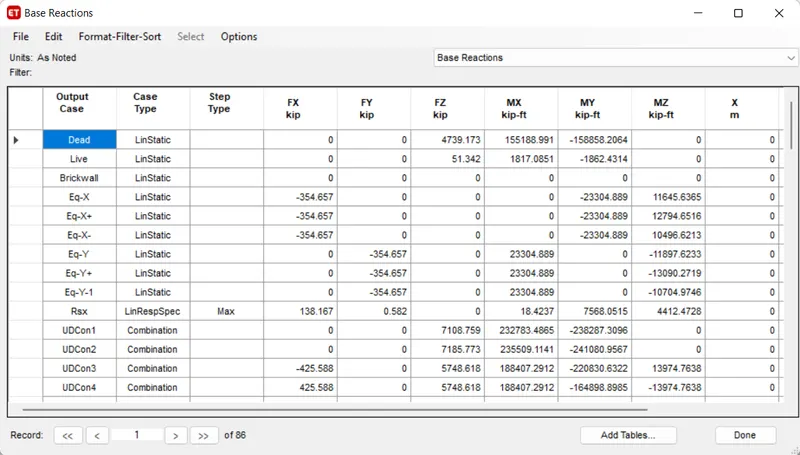
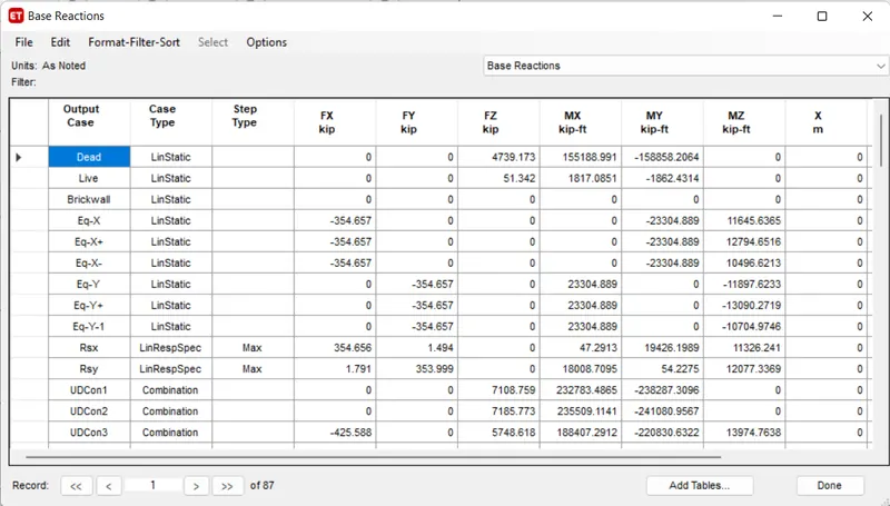
32. We have to check EQ should be close to the RS , We should calculate the

- Now substituting the value from the table ,
At X- direction -> ( 354.657 / 138.167) X 386.089
-> 991.04
At Y- direction -> ( 354.657 / 115.05) X 386.089
-> 1187.96
33. Now we put above value as scale factor for Response Spectrum at X and Y direction.
34. Now click on display -> show tables -> Analysis result structure output -> model information -> model periods and frequencies.
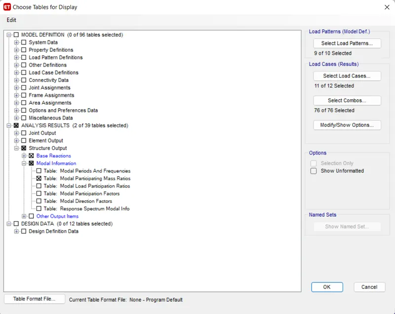
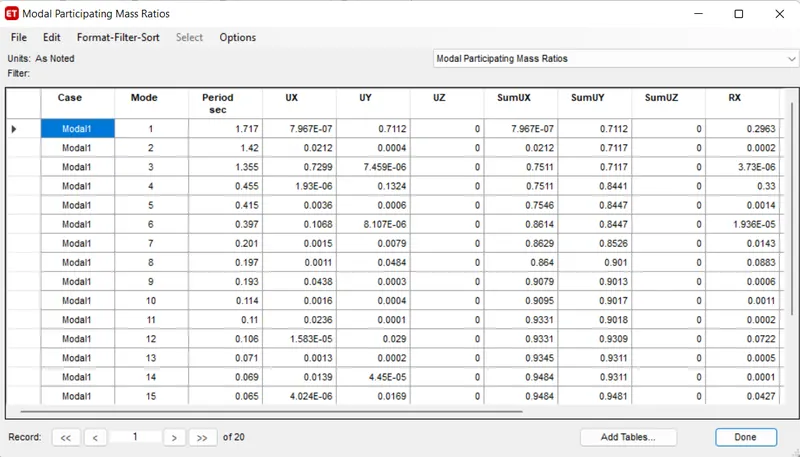
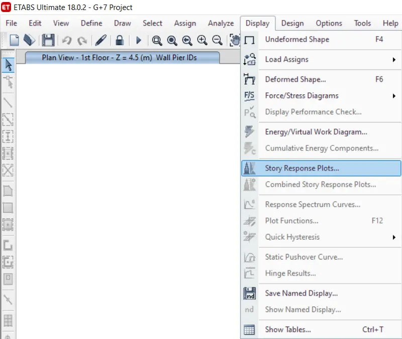
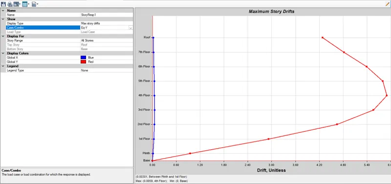
35. Select the Story Response Plot from Display option.
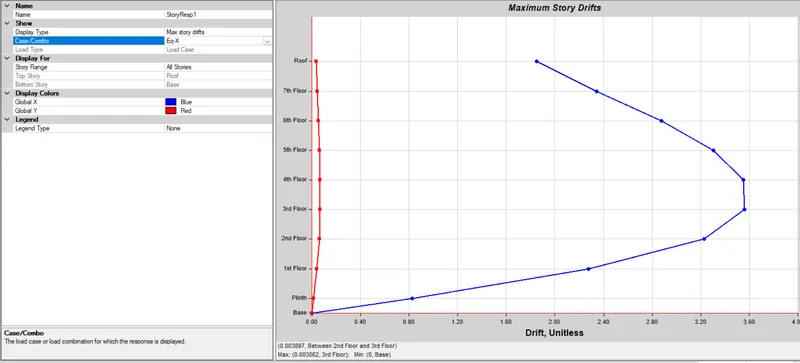
36. Story Response for maximum Story Drifts for X and Y direction is as per following.
X-Direction:
Y-Direction:
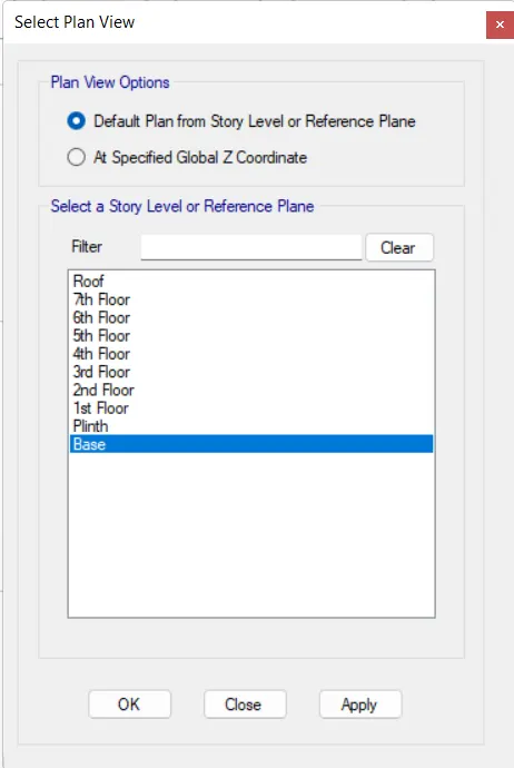
37. Next we open the Base floor in Plan view.
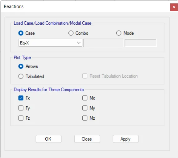
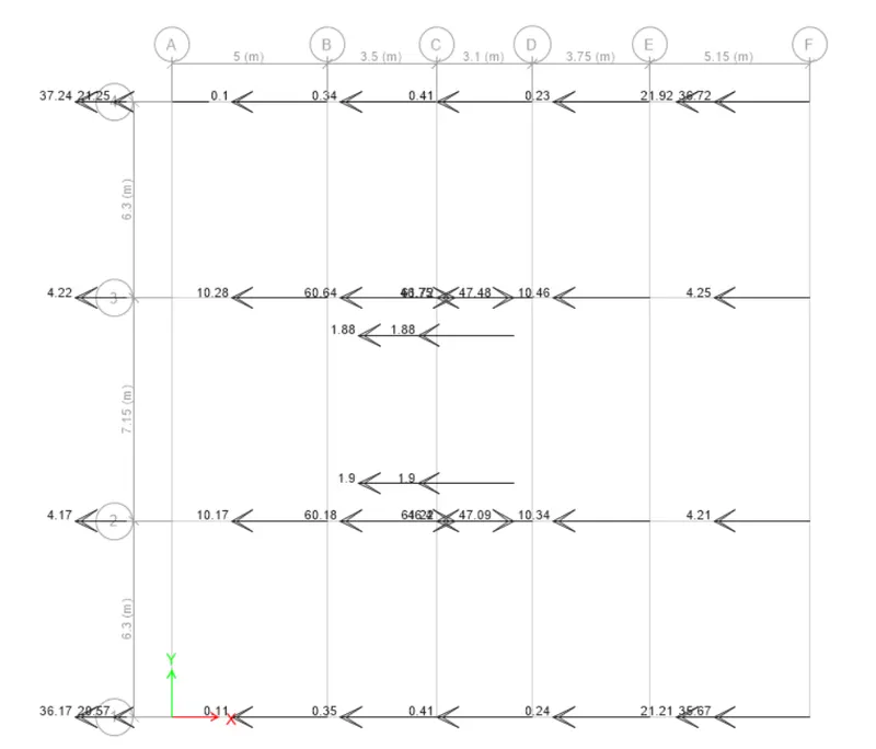
38. We have to open Reaction tab, we select the earthquake load towards in X-direction in load case.
39. When we divide base shear taken up by shear wall divided by total base shear of Building will get % of shear forces taken by Shear Wall.
RESULT: Modeled and analyzed G+7 residential plan from given architectural drawings using Etabs 2018 and run a modal response spectrum analysis and check analysis results of the etabs model.