Sketch a G+1 residential plan according to Vaastu Shastra and Calculation of Loads as per IS code
Aim: To sketch a G+1 floor residential plan, according to Vaastu Shastra, and list down the names of the structural drawings required to be provided to the site for construction. Also, assume the sizes of the structural elements (Column, Beam, Slab, etc.,) and accordingly calculate the individual corresponding loads from the members as per IS code.
Introduction: As project suggests G+1 floor residential plan of building as per Vaastu Shastra based on the structural drawings reuired to be provided to the construction site are;
The list of drawings that is mandatory to be provided to the site:
- Architectural drawings: It is drawings prepared by the architects to convey the design idea of project.
- Setting out plan: This plans include site layout proposal with built structure and its positioning according to references of markings or grid layout marked on the site.
- Centreline plan: This plan contains the centrelines which are the grids that mark the positioning of any structural or non-structural element on-site about on the grid. Centrelines are depicted as Dash-Short Dashed line-type in drawings. Centreline Plans are used to generalise a common grid reference for all type of related construction works.
- Floor plan: Architectural floor plans are provided for construction of elements through markings and detailed dimensional distance from them concerning the centre line grid.
- Section and Details: Sections are drawings depicting vertical sectional plane projections of the building showing its Interior and Exterior profiles and vertical dimensions of elements.
- Elevation and finish details: Elevations are referential for the contractor or building to keep a check on how the building should shape after completion.
- Opening schedules: Door-Window Schedules are a way of presenting complicated details of different doors and windows.
- Structural Drawings: Structural Components of the building and representing the interconnectivity of beams, columns, stairs, slabs and thus alike.
- Centre Line drawing: Centreline Plans are used to generalise a common grid reference for all type of related construction works.
- Footing and Column layout with reinforcement details: This consists of the footing and column how they are to be layed, how much reinforcement detailings are used is given inthis clearly, no of footings present and columns how they are planned.
- Column Schedule with reinforcement details: Column schedule is about the detailed diagrams of the column schedules which give an idea of the bars and size od the reinforcement bars used to construct are given in it.
- Plinth Beam layout with reinforcement details: This layout gives the orientation of the Tie Beam to the column and also the Cross-section sizes with specifications of the design.
- First Floor Beam layout with reinforcement details: The beam layout with reinforcement bars used with proper bar bending schedules are clearly provided it is repeated for the construction site depending on the no of floors constructed if example a three stored building is constructed then for each floor a separate drawing is drawn to show the beam layout clearly.
- First Floor slab layout with reinforcement details: The slab layout with reinforcement bars used with proper bar bending schedules are clearly provided. This is also repeated depending on the number of floors present in the building construction.
- Lift pit and Headroom reinforcement details: A drawing is also mentioned which shows the lift pit and also if any headroom for providing any new water tank on the top of the building for which if any columns are added specially then they are hatched so that it is understanable by the structural engineers while checking the new drawing.
- Consultant Drawings: These are the drawings given by consultants for allocation of the services to the drawings.
- Mechanical Drawings: These drawings consists of heating, ventilation, air conditionings to be fixed in the structure, the location of shafts/ mechanical ducts for all the connections are traced in each plan clearly. The marks of supply inlets and outlets are marked perfectly in the plan.
- Electrical Drawings: These drawings consists of electrical legend, lighting plans, wiring plans, switch equipment legend. The markings of the switch-board locations are marked properly.
- Plumbing Drawings: Water supply layout are planned perfectly like inlet and outlet pipes of various fixtures, lists of plumbing fixtures with sizes, number, brand, manhole osition with nomenclature and sizes, plans depicting pipelines for discharge management with size ans slope of inclination are also marked
- Fire Safety Drawings: This consists of layout plans of fire safety exists layout plans for each floor. Evacuation routes with direction locatios are added into floor plans.
Basic principles of Vaastu Shastra are:
- Rooms should be preferred to be in square/ rectangle.
- A room should be free for the fresh air to flow, sunlight falls in the home very nicely, they should look clean and bright.
- The heavy furnitures must be kept south-west direction in the home.
- Water related containers and plants should be avoided in keeping them in bedroom.
- The dining should be provided near to the kitchen and should be avoided keeping near main door of the home.
- Mirror should be strictly avoided facing the bed.
- Acoording to vaastu kitchen should be on south-east for best and must be avoided in north-east direction.
- Acoording to vaastu staircases for duplex houses should be on south-west for best and must be avoided in north-east direction.
- Acoording to vaastu toilets should be on north-west for best and must be avoided in north-east direction.
- Acoording to vaastu master bedroom should be on south-west for best.
- Acoording to vaastu guest room should be on north-west for best.
- Acoording to vaastu living room should be on north-west for best.
- Acoording to vaastu over head tanks should be on west for best.
- The main door should be provided in north, east or in north-east directions, and it should be bright and dark painting shall be avoided.
- If mirror is placed in the living room then its made sure that it should be placed in the north wall.
- If aquarium is present it can be placed on north or east wall for prosperity.
- Bedrooms are avoided to be placed in north-east as it may cause health issues and also sleeping with head in north is avoided.
- Even usage of paintings of depicting water or a fountain as it could cause emotional outbursts.
- For pooja room it should be done in east or north-east part to ensure perfect place to perform spiritual rituals also for medidating.
- The water sink in the kitchen should be placed away from the gas stove and fridge is to be placed at south-west corner.
The plan for G+1 residential building is drawn and the Vaastu is set accordingly.
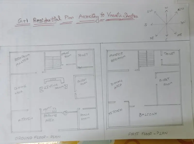
Procedure:
Calculation of loads applied on the structural elements of the columns, beams, slab is done using IS 875 Part 1 for Dead loads, IS 875 Part 2 for Live loads, IS 875 Part 3 for Wind loads are used.
Assumed sizes of the structural elements are:
Dimensions of the column = 350mm * 350mm
Dimensions of the beam = 300mm * 450mm
Thickness of the slab = 250mm
Thickness of the walls = 230mm
Height of the wall in ground floor = 4m
Height of the wall in first floor = 3.5m
Dead load calculations:
1. Dimensions of the Column = 0.35m x 0.35m
Height of the column = (slab thickness x 2)+Height of wall for ground floor+Height of wall for first floor
= (0.25 x 2) + 4 + 3.5
= 8m
Total volume of one column = 0.35 x 0.35 x 8 = 0.98 m^3
Unit weight of RCC is taken from IS 875 Part 1
Unit weight of the concrete = 25 KN/m^3
Dead load of the one column = 25 x 0.98 = 24.5 KN
2. Dimensions of the Beam = 0.3m x 0.45m
Volume of the concrete beam per meter length = 0.3m x 0.45m x 1m = 0.135m^3
Unit weight of RCC is taken from IS 875 Part 1
Unit weight of the concrete = 25 KN/m^3
Dead load of the beam = 25 x 0.135 = 3.375 KN
3. Dead load of the slab for 1m x 1m, because slab is always designed for a span of 1m^2.
Volume of the slab = 1m x 1m x 0.25m = 0.25m^3
Unit weight of RCC is taken from IS 875 Part 1
Unit weight of the concrete = 25 KN/m^3
Dead load of the slab = 25 x 0.25 = 6.25 KN
4. Height of the ground floor wall = 4m
Thickness of the wall = 230mm
Unit weight of brick masonry is taken from IS 875 Part 1
Unit weight of brick masonry = 20 KN/m^3
Dead load of the ground floor wall per unit meter length = 4 x 0.23 x1 x 20 = 18.4 KN
5. Height of the first floor wall = 3.5m
Thickness of the wall = 230mm
Unit weight of brick masonry is taken from IS 875 Part 1
Unit weight of brick masonry = 20 KN/m^3
Dead load of the first floor wall per unit meter length = 3.5 x 0.23 x 1 x 20 = 16.1 KN
Total dead load of the walls in the G+1 residential building = 18.4 + 16.1 = 34.5 KN
Live load calculation:
From the code of Live loads as per IS 875 Part 2 the values for the G+1 residential building in the project are given for the specific rooms as
For Living room = 2.0 KN/m^2
For Kitchen = 2.0 KN/m^2
For Bedroom = 2.0 KN/^2
For Toilet = 2.0 KN/m^2
For Guest room = 2.0KN/m^2
For Store room = 3.0 KN/m^2
For Staircases = 3.0 KN/m^2
For Balconies = 3.0 KN/m^2
Wind load calculation:
As the height of the building is not more than 10m. The total height of the building is 7.5m so, wind loads are not considered in the calculations.
Results: The G+1 residential building is drawn as per the Vaastu Shastra and the loads calculated using the code of IS 875 Part (1, 2, 3) for Dead load, Live load and wind load.
Dead load of the column = 24.5 KN
Dead load of the beam = 3.375 KN
Dead load of the slab = 6.25 KN
Dead load of the whole wall (Ground floor + First floor) = 34.5 KN
For Living room = 2.0 KN/m^2
For Kitchen = 2.0 KN/m^2
For Bedroom = 2.0 KN/^2
For Toilet = 2.0 KN/m^2
For Guest room = 2.0KN/m^2
For Store room = 3.0 KN/m^2
For Staircases = 3.0 KN/m^2
For Balconies = 3.0 KN/m^2