Drafting of various geometries using Chamfer, Fillet tool in AutoCad
1.
AIM: To use different tools in the cad and draw geometrics
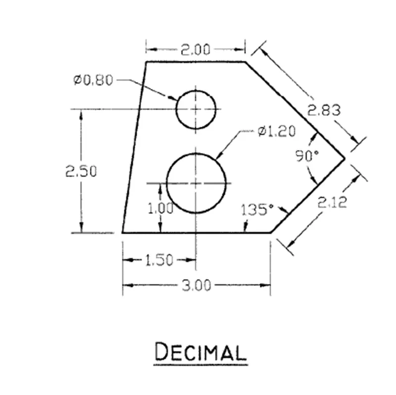
INTRODUCTION: Autocad is a software used to create 2D and 3D plans for civil engineering works.
PROCEDURE:
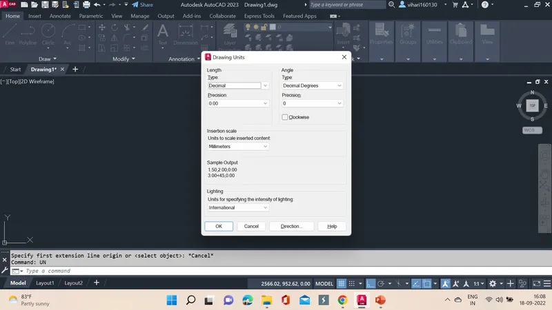
- Open CAD software new file and then units are set to decimals.
- L command is used to start the geometric and then a point is specified on the plane.
- Now, a line 3 is specified and a line is drawn.
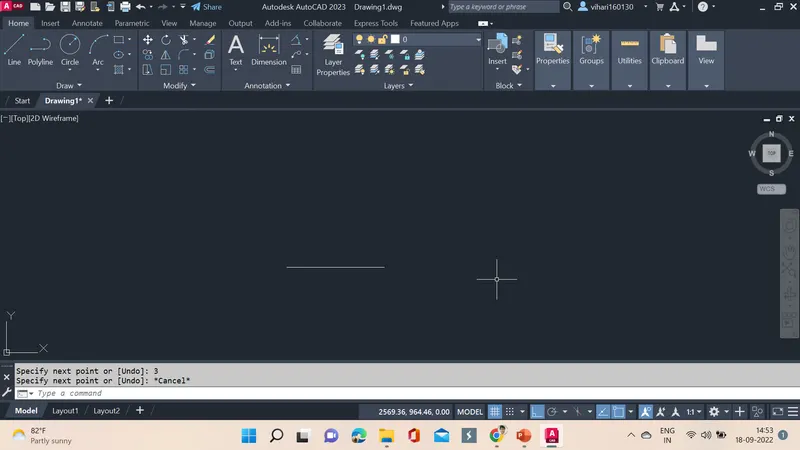
4. next line is drawn using @2.12<45
5. next line is drawn using @2.83<135
6. next line is drawn using @-2,0
7. now the line is joined with the starting point selecting it or pressing on it.
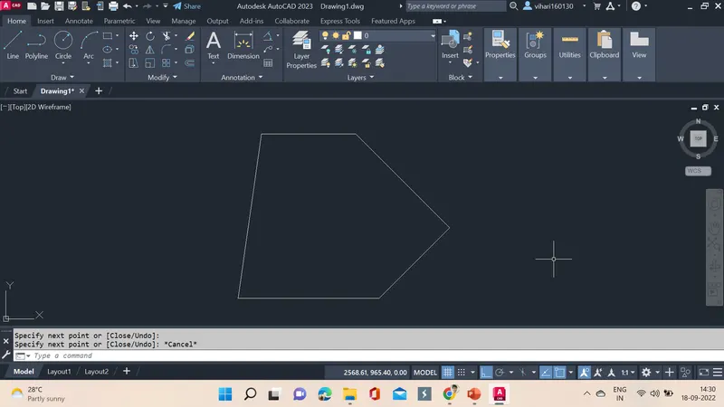
8. A line of @1.5,0 is drawn from the starting point.
9. A line of @0,1 is drawn in the upward direction.
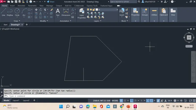
10. A circle is drawn next with the centre at 1, using C command centre is selected on top of the 1.
11. Diameter of the circle is specified as 1.20.
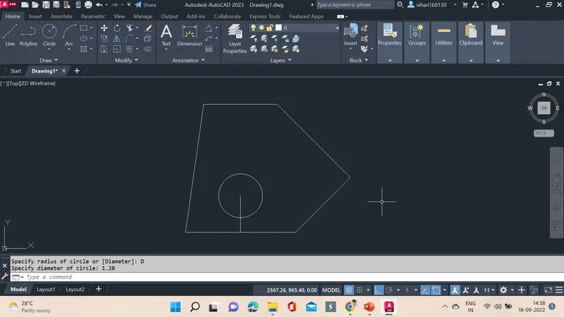
12. next circle is drawn above this at 1.5 distance from this centre.
13. 1.5 line is drawn then, C is used to draw circle, the diameter specified is 0.80.
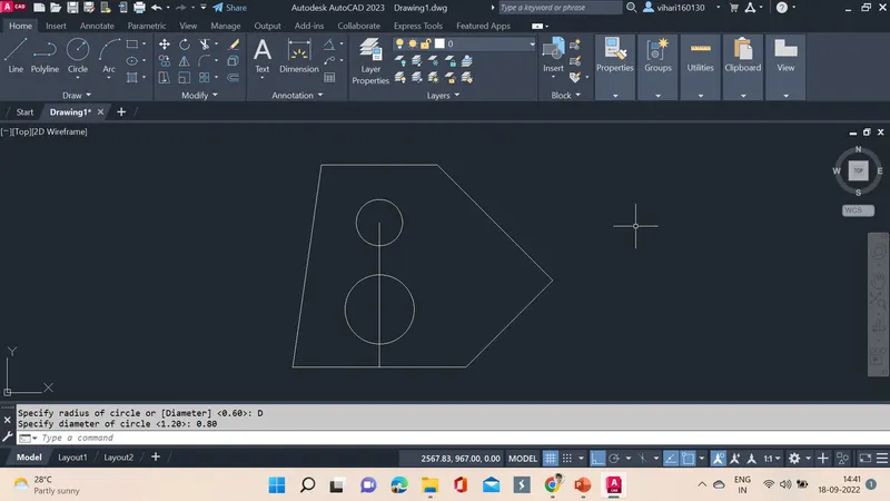
14. the lines drawn are removed by selecting them and using E erase command.
15. the DIM is used and the dimensions of the geometrics is specified if it is not in decimal then can be changed to decimal in DIMSTY.
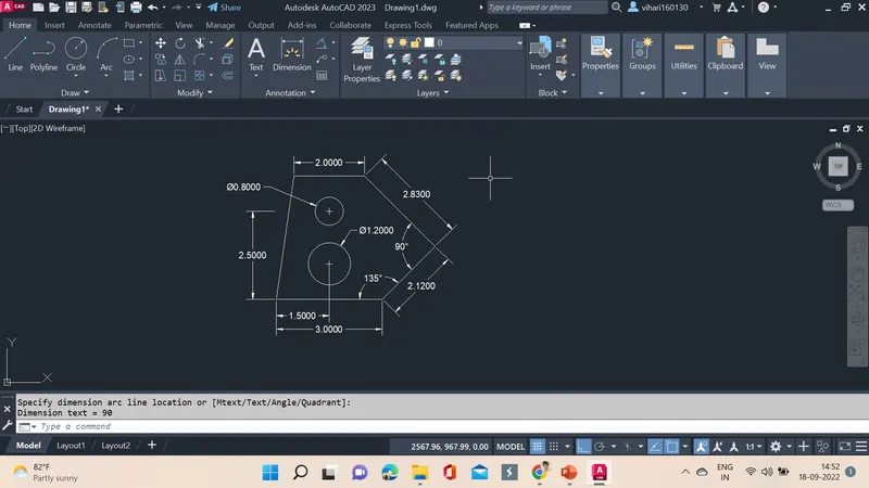
RESULTS: Successfully geometric is drawn using L, C, DIM, E, DIMSTY commands.
2.
AIM: To use different tools in the cad and draw geometrics
INTRODUCTION: Autocad is a software used to create 2D and 3D plans for civil engineering works.
PROCEDURE:
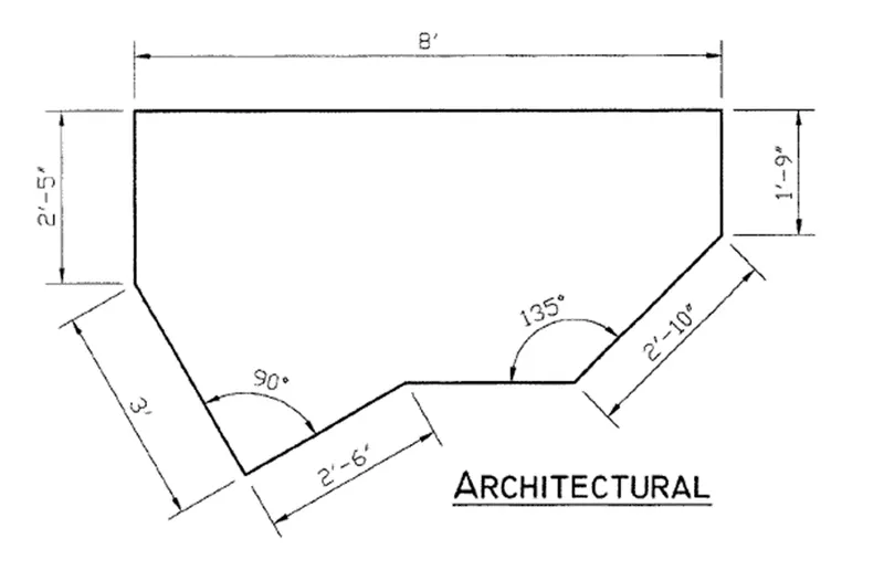
- Open CAD software new file and then units are set to architectural.
- L command is used to start the geometric and then a point is specified on the plane.
- A line 8' is drawn.
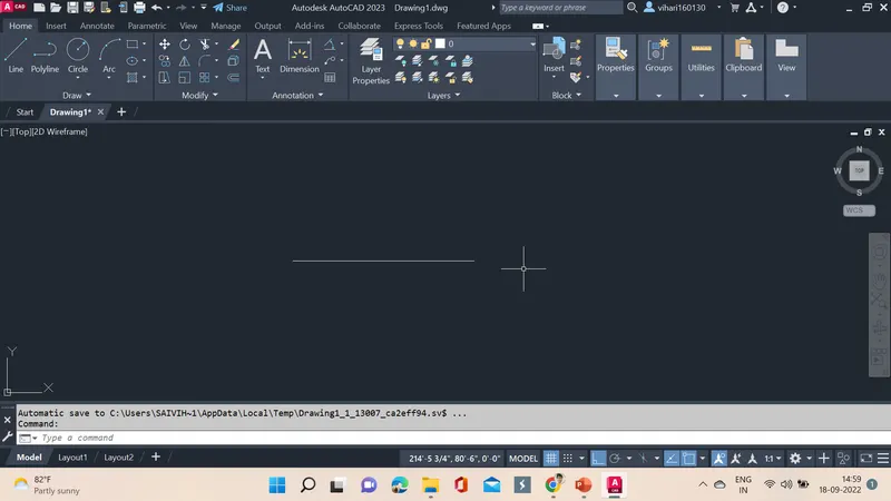
4. next a line @0. -1'-9" is drawn.
5. next a line @-2'-10"<45 is drawn.
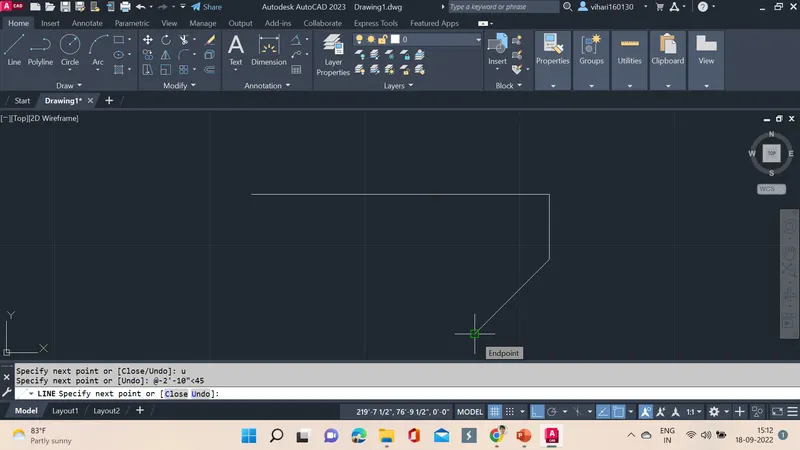
6. now the cursor is placed at the left end and a line is drawn @0,-2'-5".
7. next a line is drawn using @3'<300.
8. next line is drawn using @2'-6"<30.
9. now the line is joined with the last point completing the geometric.
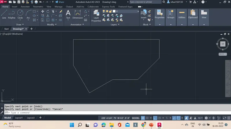
10. using DIM the dimensions are mentioned, if these are not in architectural then it is converted into them in the DIMSTY.
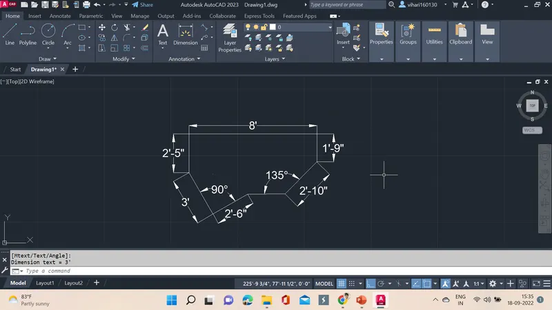
RESULTS: Successfully geometric is drawn using L, DIM, DIMSTY commands.
3.
AIM: To use different tools in the cad and draw geometrics
INTRODUCTION: Autocad is a software used to create 2D and 3D plans for civil engineering works.
PROCEDURE:
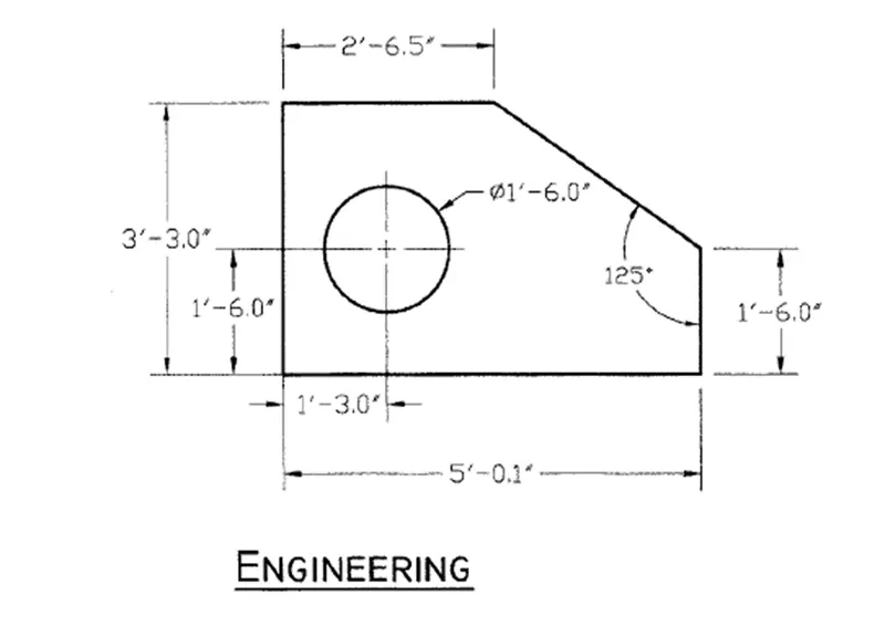
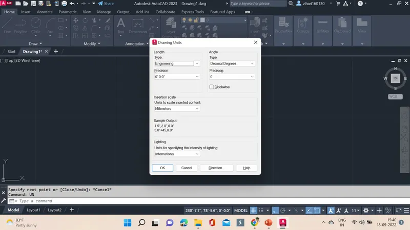
- Open CAD software new file and then units are set to engineering.
2. L command is used to start the geometric and then a point is specified on the plane.
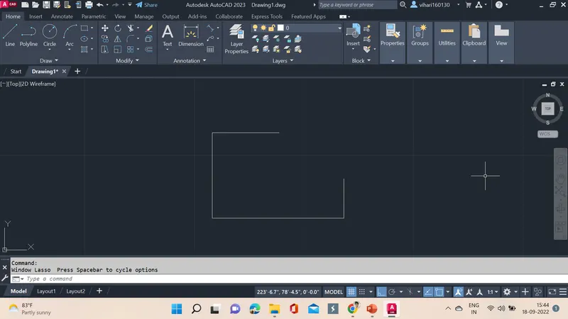
3. first line is drawn @0,-1-6.0" is drawn down.
4. next line is drawn @-5'-0.1",0 is specified and drawn.
5. next line is drawn @0, 3'-3.0" is specified and line is drawn.
6. next line is drawn @2'-6.5",0 is specified and a line is drawn.
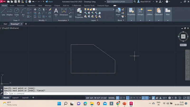
7. line from the top and right edge is joined.
8. a line from the left edge towards right is specified as @1'-3.0",0 and a line drawn.
9. towards upwards the next line s specified as @0, 1'-6.0" and line is drawn.
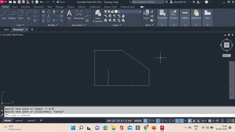
10. Now C command is used and then centre is selected at the top of the line drawn above.
11. then daimeter of the circle is drawn specifying diameeter of 1'-6.0".
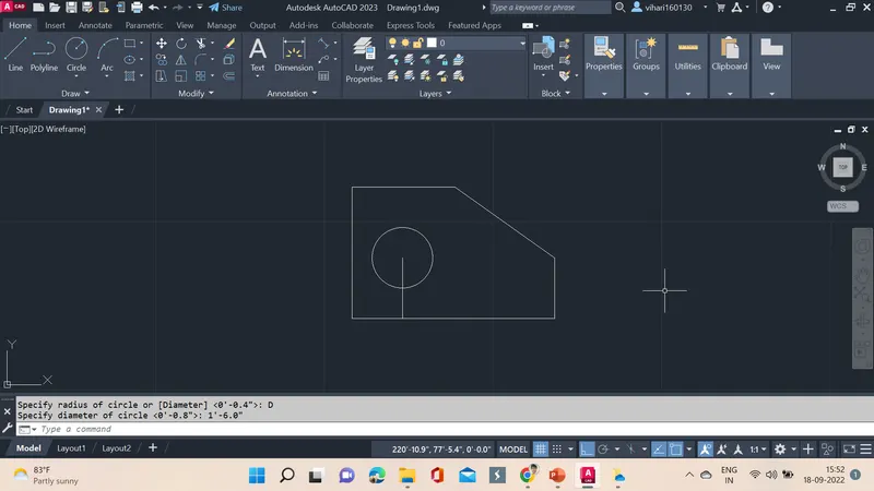
12. the line drawn is removed and the dimensions are given using DIM.
13. If the dimensions are in another units it can be changed from DIMSTY command.
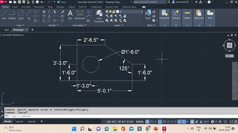
RESULTS: Successfully geometric is drawn using L, C, DIM, DIMSTY commands.
4.
AIM: To use different tools in the cad and draw geometrics
INTRODUCTION: Autocad is a software used to create 2D and 3D plans for civil engineering works.
PROCEDURE:
- Open CAD software new file and then unit are specified to decimal.
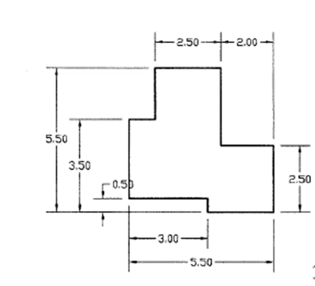
2. L command is used and then a point is specified at some point then a line is drawn @2.5,0.
3. Next point is drawn specifying @2.5,0 a line is drawn.
4. Next point is drawn specifying @0,-3 a line is drawn.
5. Next point is drawn specifying @2,0 a line is drawn.
6. Next point is drawn specifying @0,-2.5 a line is drawn.
7. Next point is drawn specifying @-2.5,0 a line is drawn.
8. Next point is drawn specifying @0,0.5 a line is drawn.
9. Next point is drawn specifying @-3,0 a line is drawn.
10. Next point is drawn specifying @0,3 a line is drawn.
11. Next point is drawn specifying @1,0 a line is drawn.
12. Next point is drawn specifying @0,2 a line is drawn.
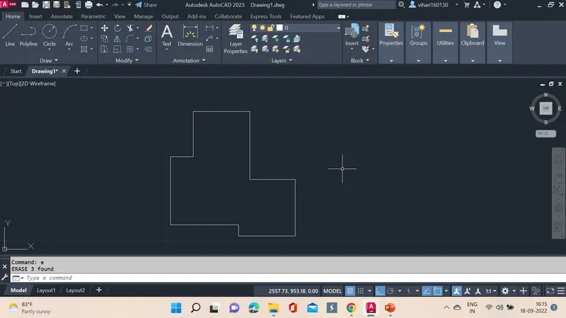
13. The dimensions are provided using DIM command.
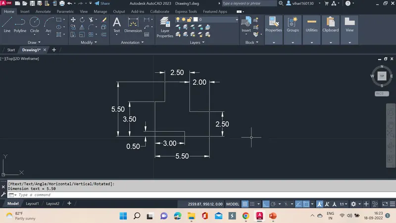
RESULTS: Successfully geometric is drawn using L, DIM, DIMSTY commands.
5.
AIM: To use different tools in the cad and draw geometrics
INTRODUCTION: Autocad is a software used to create 2D and 3D plans for civil engineering works.
PROCEDURE:
- Open CAD software new file and then unit are specified to decimal.
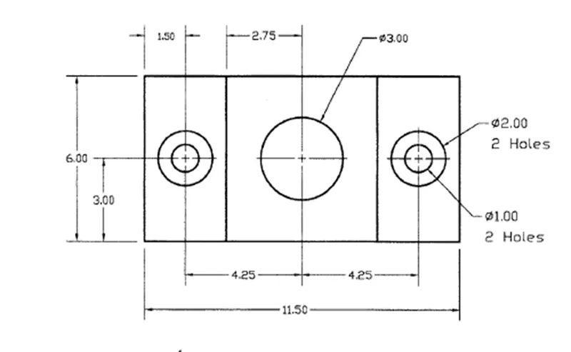
- RECT command is used dimensions are given as length 11.50 and width 6.0.
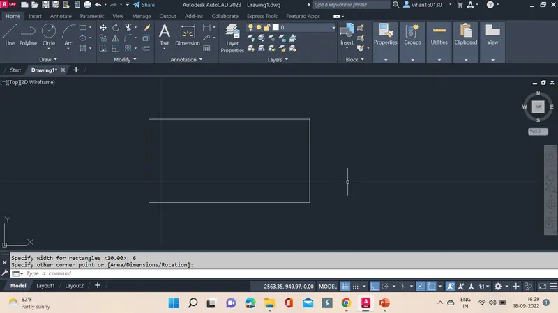
3. A line is drawn from one edge towards up with length @0,3.
4. Then a line is drawn specifying the point as @1.5,0.
5. C is set in the command and a circle is drawn with daimeter of 2.
6.C is given in the command another circle is drawn inside it using diameter as 1.
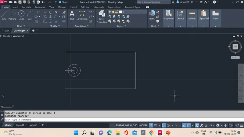
7. now the process is repeated on other side using the same process.
8. now length is specified as @0,3 a line is drawn.
9. now next length is specified as @-1.5,0 and a line is drawn.
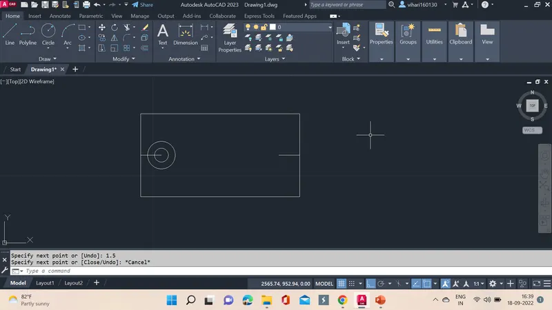
10. C is set in the command and a circle is drawn with daimeter of 2.
11.C is given in the command another circle is drawn inside it using diameter as 1.
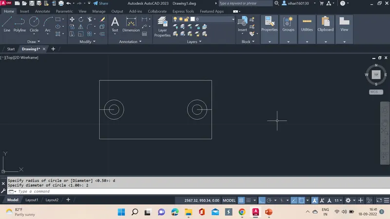
12. the lines drawn for this are removed using E command.
13..L command is set and enter is clicked.
14.next a line is specified @3,0 a line is drawn.
15.next point is specified @0,6 a line is drawn.
16.next point is specified @5.5,0 a line is drawn.
17.next point is specified @0,-6 a line is drawn.
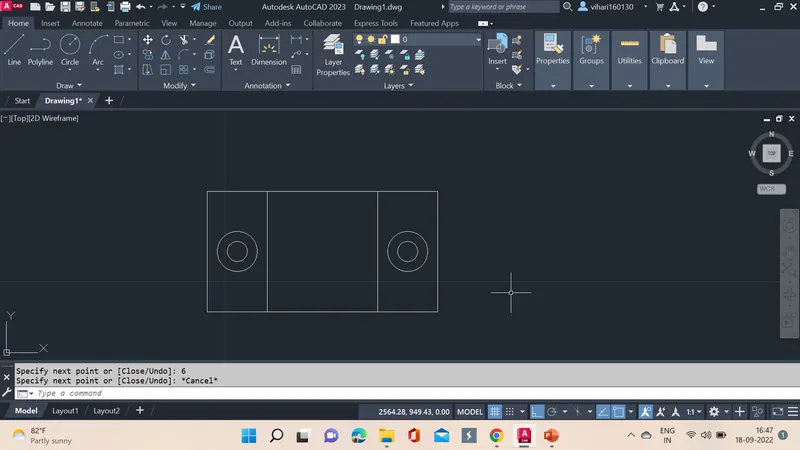
18. a line is drawn specifying the point @-2.75,0.
19. now a line is drawn specifying the point @0,3.
20. C command is entered and then a circle is drawn by selecting the point from the line.
21. now diameter is given as 3.
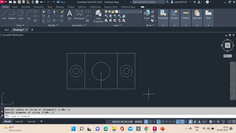
22. now the line is removed using E command and then using DIM dimensions are mentioned.
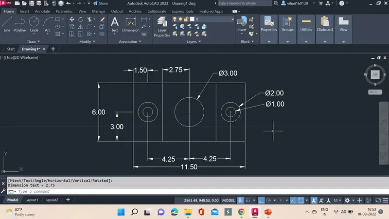
RESULTS: Successfully geometric is drawn using L, C, DIM, DIMSTY commands.
6.
AIM: To use different tools in the cad and draw geometrics
INTRODUCTION: Autocad is a software used to create 2D and 3D plans for civil engineering works.
PROCEDURE:
- Open CAD software new file and then unit are specified to decimal.
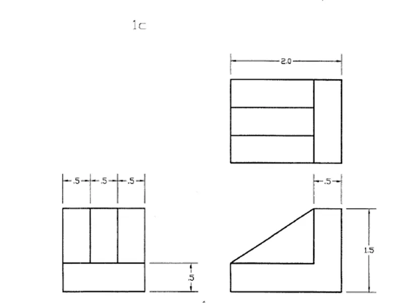
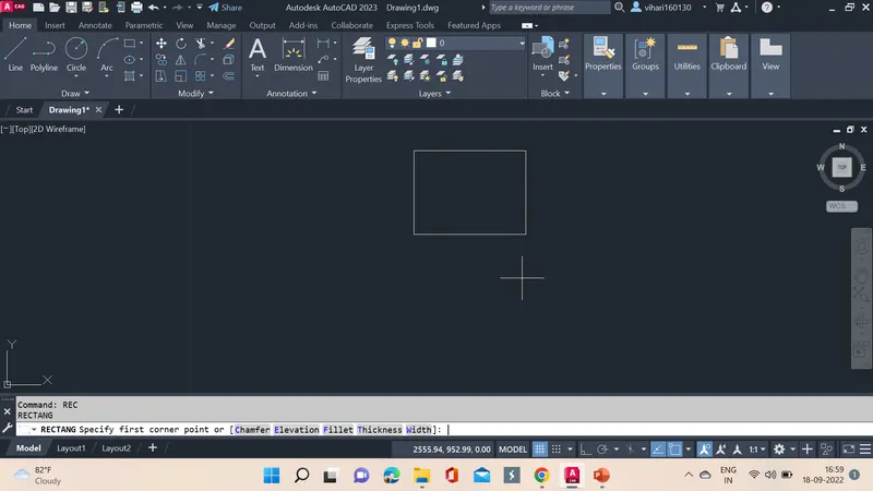
- REC is specified and the D is selected.
- Now the dimensions are specified as length 2 and width 1.5.
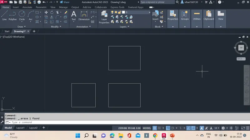
4. CO is typed and entered then the rectangle is selected.
5. Then other rectangle is drawn using the same model object.
6. other rectangle is made as taking this point as base with dimensions 1.5 length and width of 1.5
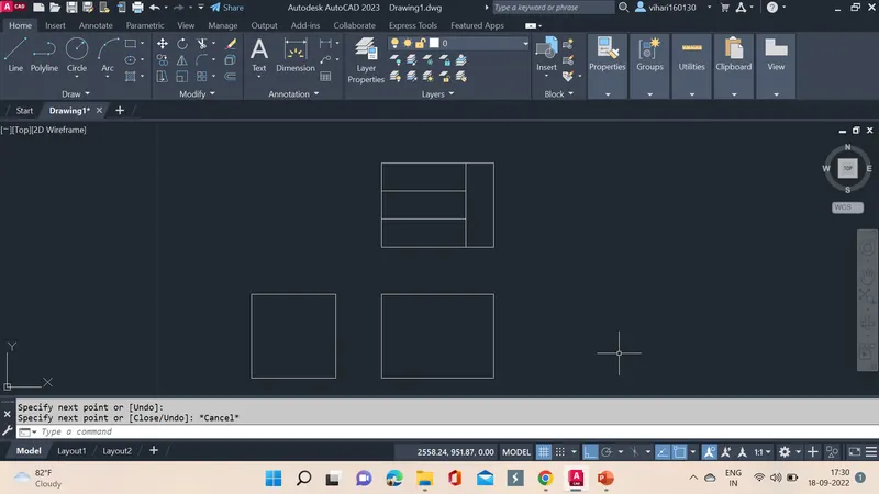
7. in the top rectangle L is entered and @-0.5,0 is specified a line is drawn.
8.next step line @1.5,0 is specified and drawn.
9.next line is specified as @0,-0.5 is drawn.
10.next point is specified as @-1.5,0 is drawn.
11.next line is specified as @0,-0.5 is drawn.
12.next point is specified as @1.5,0 is drawn.
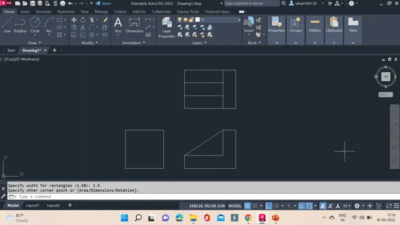
13. in the next rect, L command is used a line is specified as @-0.5,0
14.next line is specified as @0,-1 and then line is drawn.
15.next line is specified as @-1.5,0 and then line is drawn.
16. now the line is drawn from this point to the upper point and the rest lines are removed using E erase command.
17. now the last one is divided using line command L and a corner is specified @0,0.5 a line is drawn.
18. next point is specified as @0.5,0 and line is drawn.
19. next point is specified as @0,1 and line is drawn.
20. next point is specified as @0.5,0 and line is drawn.
21. next point is specified as @0,-1 and line is drawn.
22. next point is specified as @0.5,0 and line is drawn.
23. now a line is drawn closing the gap in them.
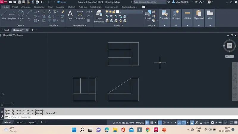
24. last step is to give dimensions of the geometric using DIM.
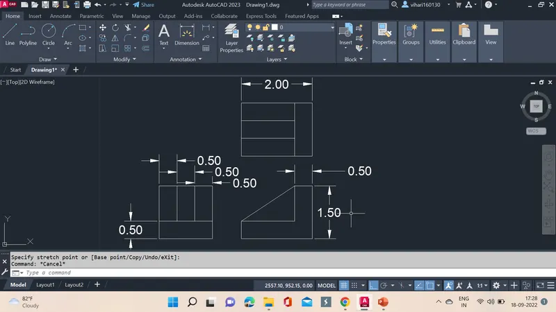
RESULTS: Successfully geometric is drawn using L, DIM, commands.
7.
AIM: To use different tools in the cad and draw geometrics
INTRODUCTION: Autocad is a software used to create 2D and 3D plans for civil engineering works.
PROCEDURE:
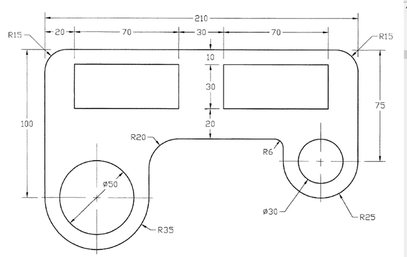
- Open CAD software new file and then units are set to decimals.
- L is used to draw the line a point is specified.
- A point @0,100 is specified and a line is drawn.
- A point @210,0 is specified and a line is drawn.
- A point @0,-75 is specified and a line is drawn.
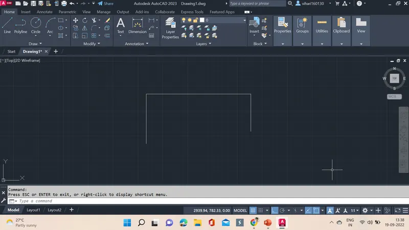
6. F is specified and then radius is selected.
7. After the radius is selected 15 is specified.
8. The lines on the left are both selected and then fillet is done using specified radius 15.
9. The lines on the right are both selected and then fillet is done using specified radius 15.
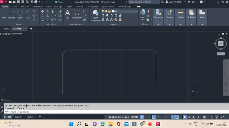
10. L is used and then left bottom is selected and towards right @70,0 is specified and drawn.
11. L is used and then right bottom is selected and towards left @-50,0 is specified and drawn.
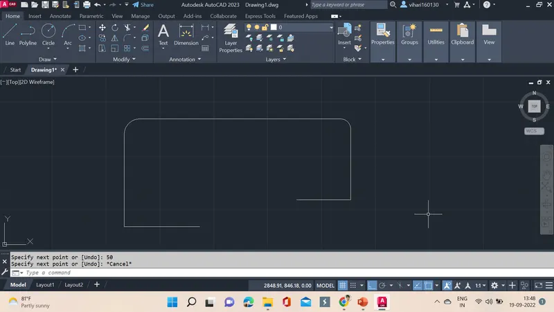
12. Now midpoint is taken and C is specified and then diameter is selected and 50 diameter a circle is drawn in left end.
13. Now midpoint is taken and C is specified and then diameter is selected and 30 diameter a circle is drawn in right end.
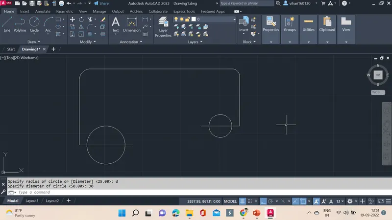
14. Arc is selected from the ribbon then first point is selected.
15. next end is selected then radius is chosen and radius is given as 35.
16. Arc is selected from the ribbon then first point is selected.
17. next end is selected then radius is chosen and radius is given as 25.
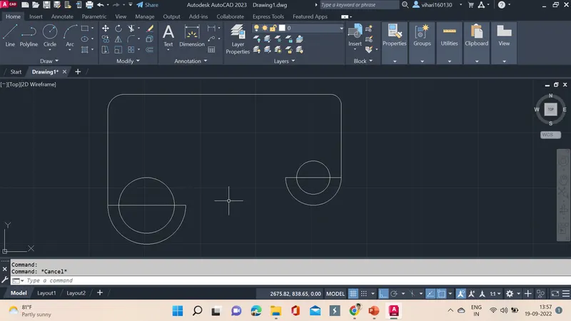
18. the lines in between them are trimmed.
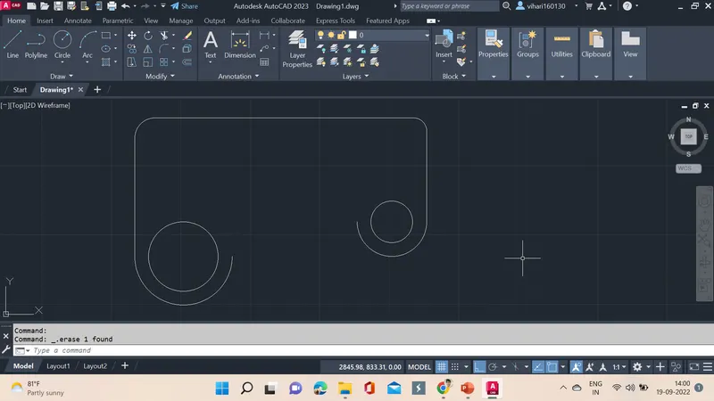
19. a line is drawn from the top @20,0 specified.
20. REC is specified in the command and then dimensions are selected.
21. Now the dimensions length is specified as 70, now width is specified as 30.
22. Now CO is used and the rectangle is selected and then enter is clicked now.
23. Now displacement is given as 100 from the starting point.
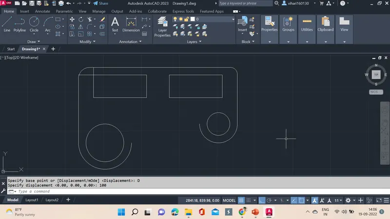
24. extra lines are trimmed or erased.
25. from the second rectangle a line using L command is drawn specifying point as @0,-20.
26. perpendicular line is drawn to this and the line is intersecting withthe radius from down.
27. excess lines are trimed using crossing.
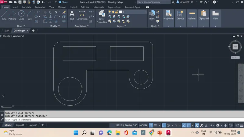
28. Now the radius is set using Fillet in the bottom, from left R is selected and 20 is given.
29. Now the radius is set using Fillet in the bottom, from right R is selected and 6 is given.
30. In the last step DIMSTY is used and set the dimensions, now DIM is used and dimensions are given.
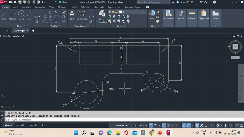
RESULTS: Successfully geometric is drawn using L, F, C, DIMSTY, DIM commands.
8.
AIM: To use different tools in the cad and draw geometrics
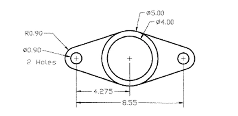
INTRODUCTION: Autocad is a software used to create 2D and 3D plans for civil engineering works.
PROCEDURE:
- Open CAD software new file and then units are set to decimals.
- C is given in the command box.
- First circle is drawn selecting D and diameter is given as 5.
- Another circle is drawn taking the same centre and diameter is given as 4.
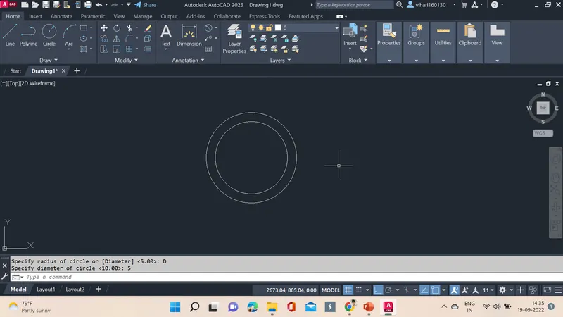
5. L command is used and a line is drawn and taking the centre of the circle and line centre lies on the same point.
6. A line is drawn specifying the point @8.55,0.
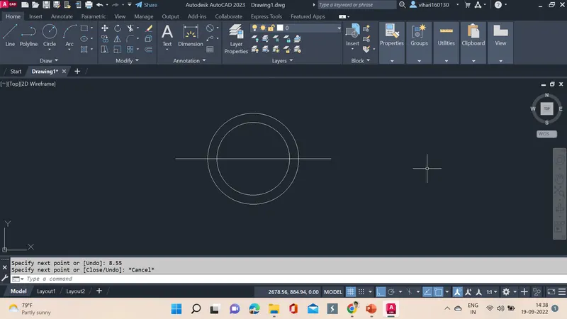
7. A line @0,0.9 is specified and drawn and then a line @0,-0.9 is drawn on the left side.
8. A line @0,0.9 is specified and drawn and then a line @0,-0.9 is drawn on the right side.
9. Arc is selected and then a point is selected and then end is selected and arc is given radius 0.9.
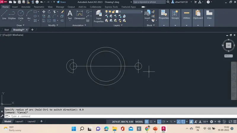
10. Arc is selected and then a point is selected and then end is selected and arc is given radius 0.9 on the right side.
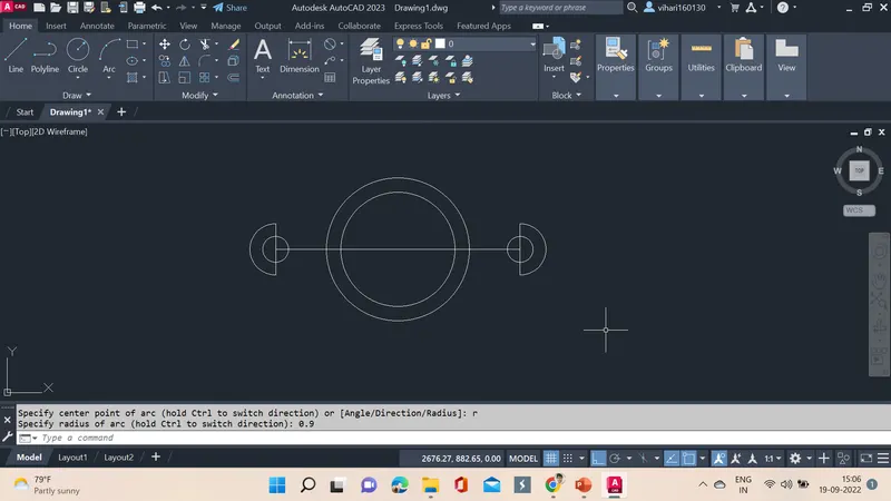
11. The excess lines are trimmed and then lines drawn to complete the figure.
12. L is selected and using object snap tangent is choosen then, Tanget is selected and lines aredrawn.
13. From all four sides of the arc 4 tangent lines are drawn.
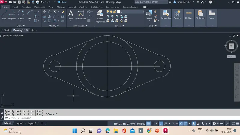
14. now the excess lines are removed and then DIM is used to give the dimensions.
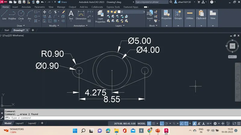
RESULTS: Successfully geometric is drawn using L, ARC, C, OBJECTSNAP, DIMSTY, DIM commands.
9.
AIM: To use different tools in the cad and draw geometrics
INTRODUCTION: Autocad is a software used to create 2D and 3D plans for civil engineering works.
PROCEDURE:
- Open CAD software new file and then units are set to engineering.
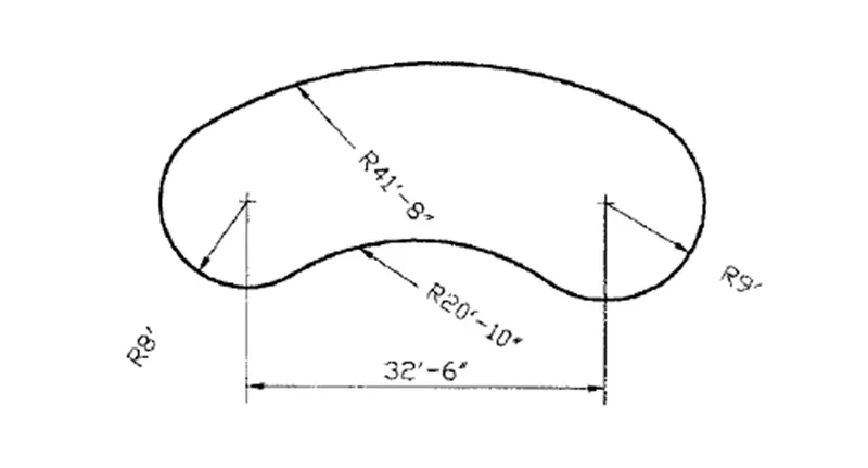
2. L command is used and then a line is drawn then it is specified using @32'-6",0.
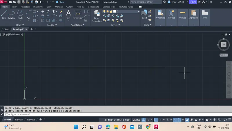
3. C command is used and then a circle at left is drawn using radius 8'
4. C command is used and then a circle at right is drawn using radius 9'
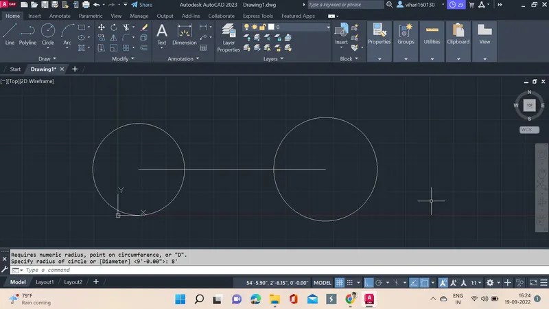
5. now C command is used then tan tan radius is selected.
6. now first point is selected on left side, then second point is selected on right side.
7. then radius is given as R41'-8".
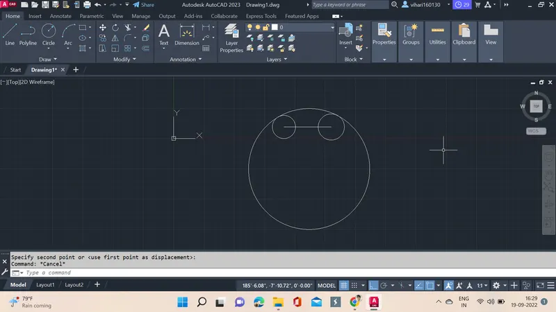
8. now C command is used then tan tan radius is selected.
9. now first point is selected on left side, then second point is selected on right side.
10. then radius is given as R20'-10".
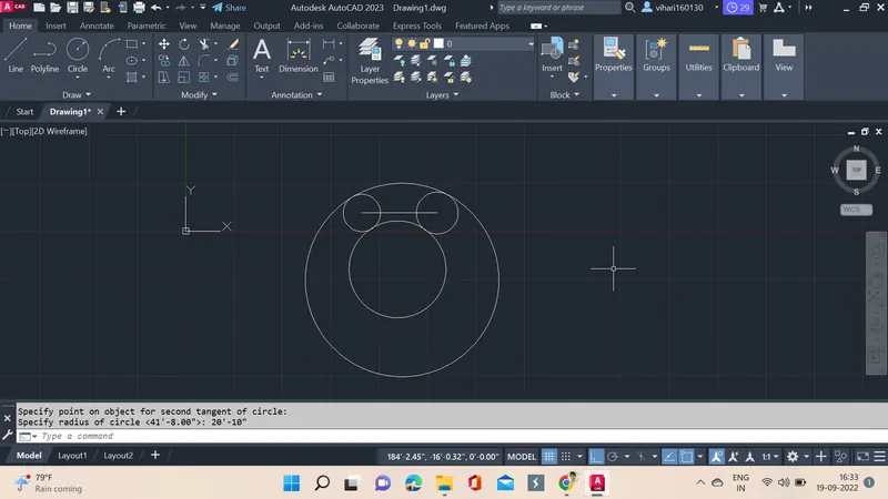
11. the excess lines should be trimmed using TRIM command.
12. DIM is used to give the dimensions.
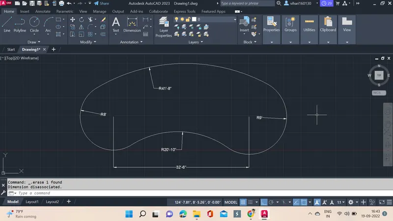
RESULTS: Successfully geometric is drawn using L, ARC, DIMSTY, DIM commands.
10.
AIM: To use different tools in the cad and draw geometrics
INTRODUCTION: Autocad is a software used to create 2D and 3D plans for civil engineering works.
PROCEDURE:
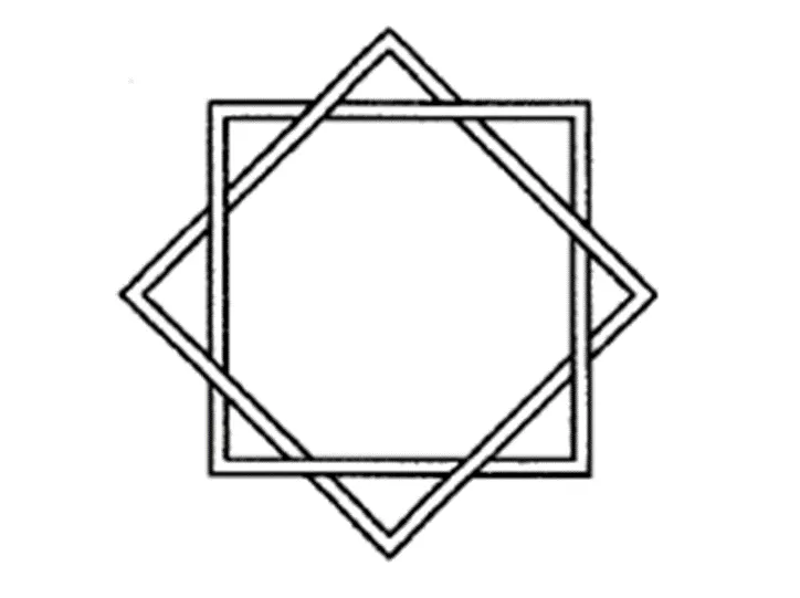
- Open CAD software new file and then units are set to decimals.
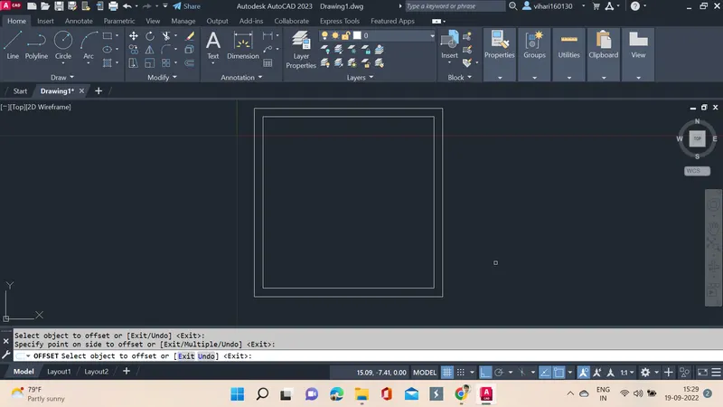
- REC is given in the dialog box and dimensions are selected.
- now length is given as 10 and width is also given as 10.
- Offset is used then 1 is given and another cube is made.
5. now RO is given in dialog box then another cube is done.
6. this is placed at centre after turning it into 45degree.
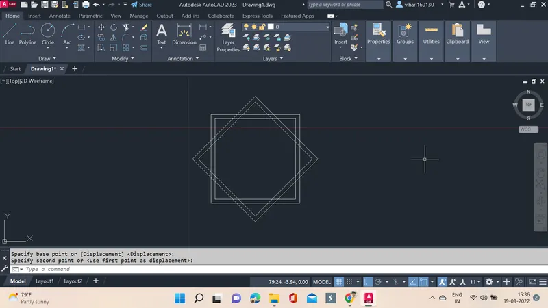
TRIM command is used and then trimmed the excess of the lines.
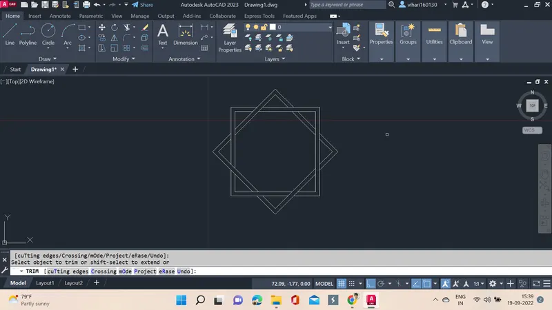
RESULTS: Successfully geometric is drawn using REC, RO, TRIM commands.
11.
AIM: To use different tools in the cad and draw geometrics
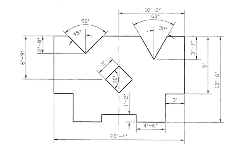
INTRODUCTION: Autocad is a software used to create 2D and 3D plans for civil engineering works.
PROCEDURE:
- Open CAD software new file and then units are set to engineering.
2. Type L in the command box and entered.
3. a point is specified the start point.
4.a point is specified at next point @2’-6”, 0
5.a point is specified at next point:@0, -1’-2”
6.a point is specified at next point @4’-6”, 0
7.a point is specified at next point:@0, 4’-6”
8.a point is specified at next point:@3’, 0
9.a point is specified at next point@0, 9’
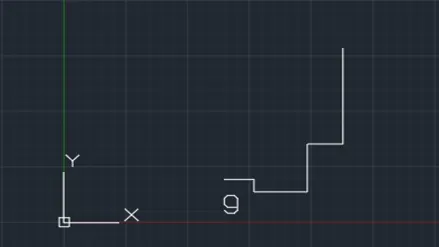
10. Type MI and entered then objects are selected.
11. Specify the first point of the mirror as
12. Specify the second point at the top
13. At Erase source object type N.
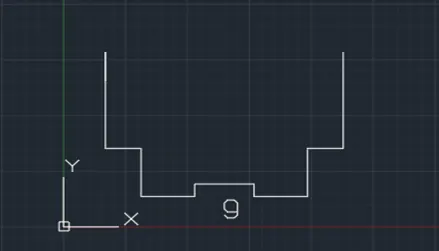
14. L is used in the command box and entered.
15. next point is specified at next point: @0, -3’-7”
16. next point is specified at next point:@-8’-7”, 0
17. With d as centre draw a line at an angle of 30 degrees till it touches the bottom line and 120 degrees towards up and close the figure at f
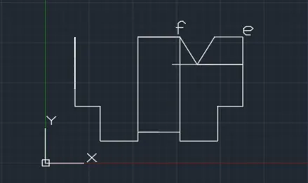
18. L is used in the command box and entered.
19. at next point specified from c.
20. next point is specified at @0, -2’-8”
21. next point is specified at @6’-7”, 0
22. With d as centre draw a line at an angle of 45 degrees till it touches the line and 135 degrees towards up and close the figure at c
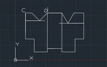
23. the excess lines are trimmed off.
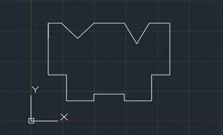
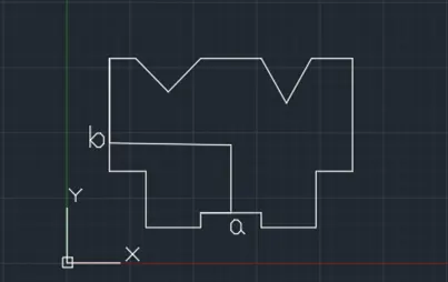
24. Draw a line from b and a so that they will intersect at the centre.
25. from point b is at a distance of 6’-9’ from the top and point a is at the centre of the baseline.
26. Rec or Rectangle is typed in the command box.
27. Specify the first corner of the rectangle, enter D for Dimensions, enter the length as 3, enter the width as 3.
28. Specify the other corner.
29. Type RO and press Enter
30.Select the object: rectangle
31.And rotate it by 45 degrees by selecting a base point.
32. Also, draw a line as diagonal to the rectangle
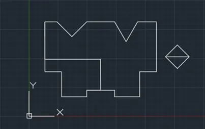
33.Place the rectangle created in the correct place using the diagonal line
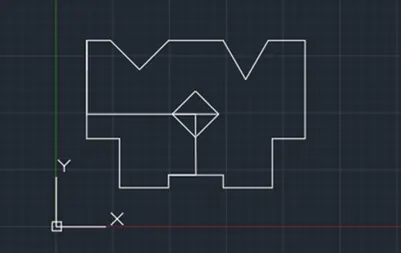
34.Delete or trim off the unwanted lines to get the final geometry
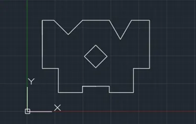
35. DIM is used and the dimensions are given
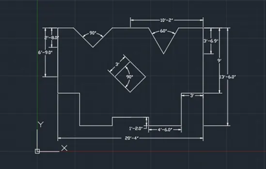
RESULT: Successfully geometric is drawn using L, RO, ARC, DIMSTY, DIM commands.