Structural Modelling using Etabs 2018
Aim
Procedure
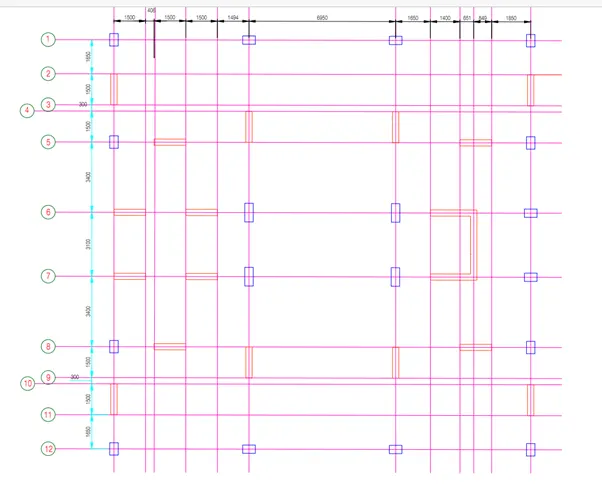
Let Us check the floor plan given and Assume the initial Considerations of the building.
- The base is Pinned
- The Building have Base + 9 Stories (Ground + 8) and Mumty Level
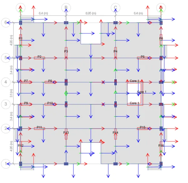
- Consider the column Size as 400 x 600 and Beam Size as 350 x 500 and Shear wall as 300mm x 1500mm. Thickness of Slab 150mm
- Live load As per IS 875 part 2 is 2kN/Sqm for Bed Room hall and 3kN/sqm for Toilets and Balconies.
- Floor Finish as Per IS 875 is 1.5KkN/Sqm and ACC block is 5kN/Sqm
- Water Tank is 20K litre and the load is 200kN
Design Considerations as per the Specifications given in the question
- Re-entrance and cut-out modification – There is large opening in the plan for Architectural purpose. This cannot be modified. So the design needs to be compromised.
- Vertical Irregularity - There is open ground floor for parking so the building undergoes soft storey mechanism.
- Planar Irregularity – By seeing the plan it is evident that the building is Symmetrical in both directions.
- 2% shear wall area with respect to building area. – (Overall area = 400Sqm 2% is 8Sqm)
- Stiffness modifier as Per Code for Column is 0.7 and for Beam is 0.35
Output
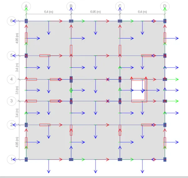
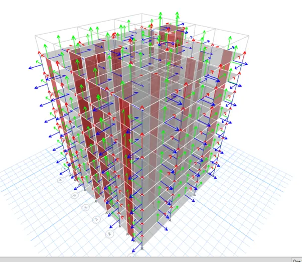
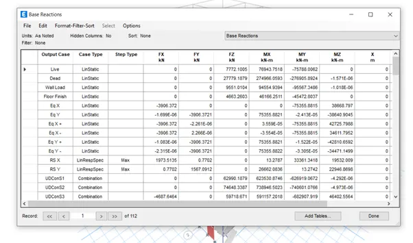
Base Reaction for Eqx is 3906 and for Eq Y is 3906
The Base Reaction for RS x is 1973 and for RS y is 1567
From this we can calculate the Scale Factor
Scale Factor for X is = (3906/1973) x 9806.65 = 19414.4
Scale Factor for Y is = (3906/1567) x 9806.65 = 24444.65
One the scale factor is finalized the Then delete Earth Quake loads and rerun the analysis with Only Response Spectrum and the scale factor.
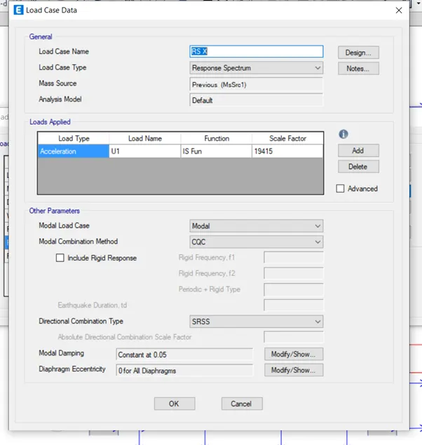
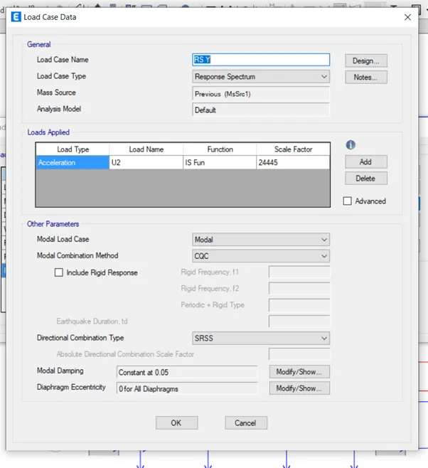
Rerun the Analysis
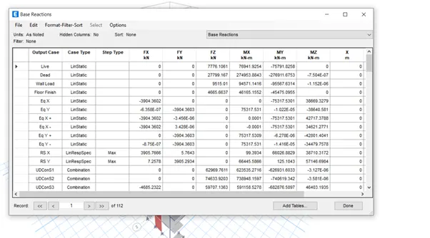
Once the Base Shear is satisfied the delete the Earthquake loads and keep only the Response Spectrum.
Then Run the Analysis.
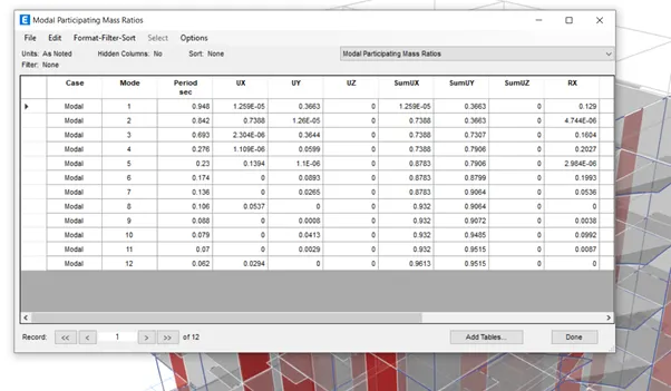
The Mass Participating ratio in 3 modes should satisfy at least 65%.
In our case the mass participating ratio satisfies 65% and above for all the 3 directions.
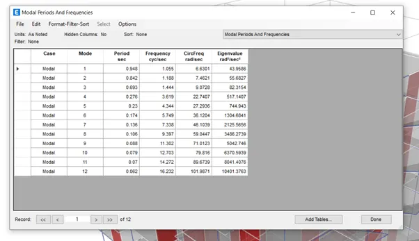
The Time period is for first two modes is at least 10%
In our case the difference is more the 10% hence achieved.
Mode 1 and 2 should be Greater than 3
In the Above table it is evident that Mode 1 and 2 is Greater than Mode 3
Inter Storey Drift Ratio limited to 0.004 as Per IS 1893 2016
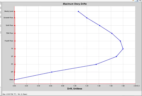
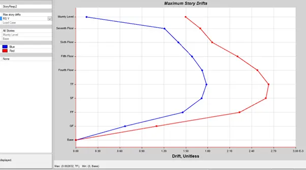
In X direction it is 0.0018 and in Y direction is 0.0026 which is less than 0.004.
Concrete Design Run and the Output is checked.
Weather there is any failure in Beams and Columns.
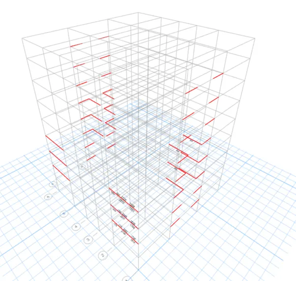
There is a failure in beam.
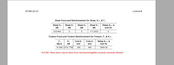
The failure is occurred due to Torsion.
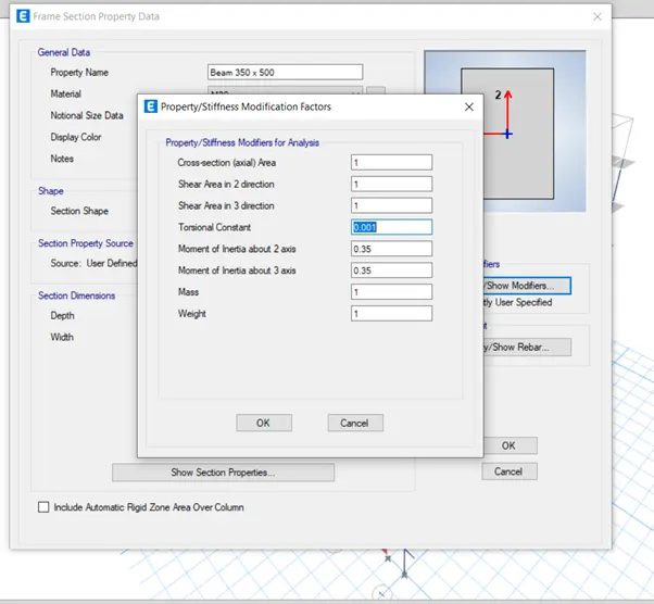
Hence Change the Stiffness modifier for torsion from 1 to 0.001
Then run the analysis.
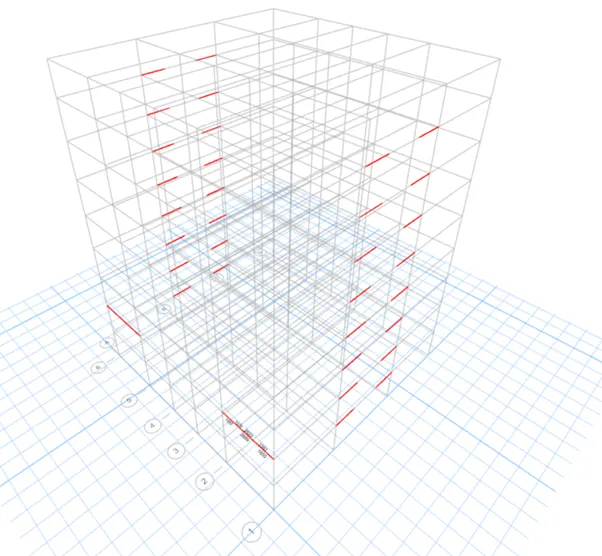

Still their a Failure in the beams.
So I will increase the size of beam for the failed columns
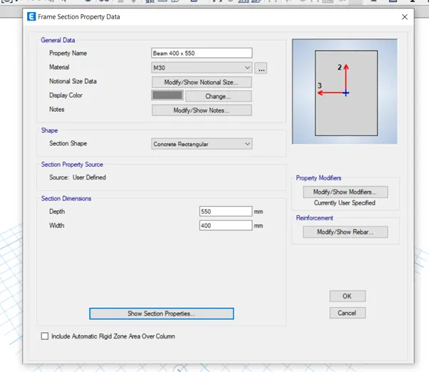
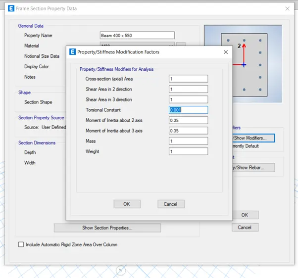
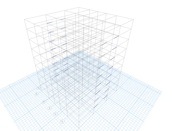
Still their is a failure in the beams. Since these beams are not continuous we will design these beams as secondary beam so that it will not take the loads.
Check the system is Dual System or Shear wal system.
Shear walls alone is taking about 77% of base shear.
As per Code for Dual Syste Moment resisting Frames to take atleast 25% of Base shear. In our case its taking only 23% Hence it is a Shear wall system.