Structural Modelling using Etabs 2018
AIM:
To model and analyse the architectural drawings for a G+7 residential building in zone 5. The floor plan is the same for all 7 floor levels. Conceptualize a framing plan layout and then model the building in Etabs.
PROCEDURE:
STEP 1-
Setup the grid lines and the storey level.
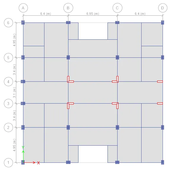
the space between the A-B grid is 6.4m, B-C grid is 6.95m, C-D grid is 6.4m
the space between the 1-2 grid is 4.95m, 2-3 grid is 3.4m, 3,4 grid is 3.1m, 4-5 grid is 3.4m, 5-6 grid is 4.95m .
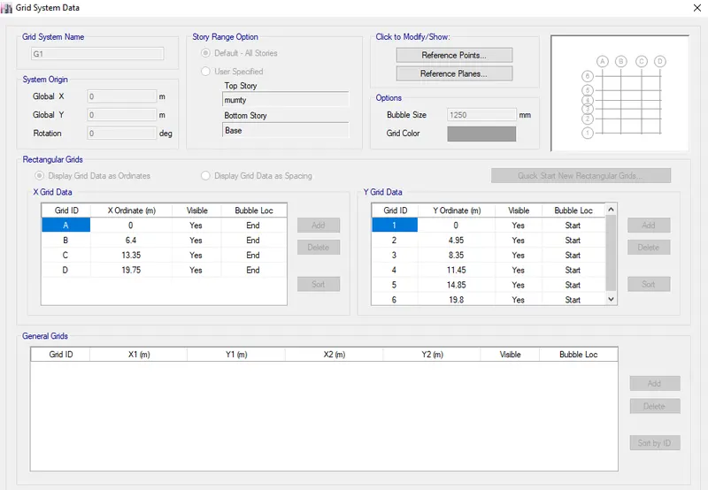
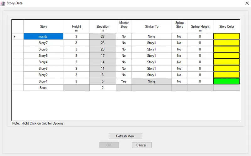
once the gris is set, the material property is to be assigned as beam, column, slab and the shear wall.
go to define > section property > frame section > add new property > select the shape of the section > give the property a name beam 250 x 500 > material as m30 > change the dimensions of the beam > modify the reinforcement of the structure and the property modifier the shear area as o.35
by the same way add the property for the column.
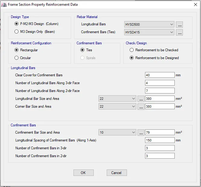
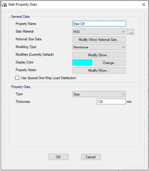
for the slab property
go to define > section property > slab section > add new property > name the slab material > slab material as m30 > input the thickness of the slab.
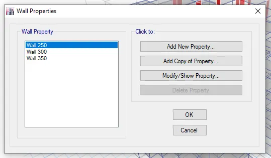
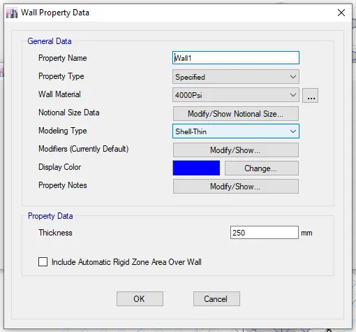
for the shear wall go to, define > section property > wall section > add new property > name the section > material type as m30 > modelling type as shell thin > input the thickness of the wall.
once the frame properties are added.
Once the load combinations are to be added to the model, adding the dead load, live load, brick wall load, floor finish load and seismic load
According to IS 456 the live load for the residential building with people less than 200 people, it should be assume the live load as 1kN/m^2 so we assign the load on the slab as 1kN/m^2 as UDL.
Go to Select > select > object type > floor.
Assign > shell load > unifrom > feed the load as 1kN/m^2.
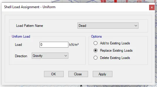
To assign the wall load select the beam which might carry the wall load.
As per the IS 1893 an expression helps to find the value for the brick load.
So we get the value as 4.5 kN/m^2
Now the structural elements can be placed on the grid.
Place the columns on the grid intersection point and the beams on the grid lines and where the beam is gonna experience wall load.
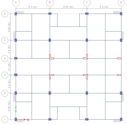
place the slabs on the where the slabs are suppose to be,
so the as per the IS 1893 the live load reduction has to be done to be reducing the live load to 10 percent to each floor.
And place the shear walls on the appropriate location as it consumes 2 percent of the structural area of the building.
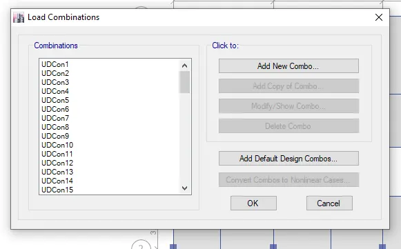
so next set the load combination go to define > load combination > add default design combo > select concrete frame design and concrete shear wall, convert to user combination.
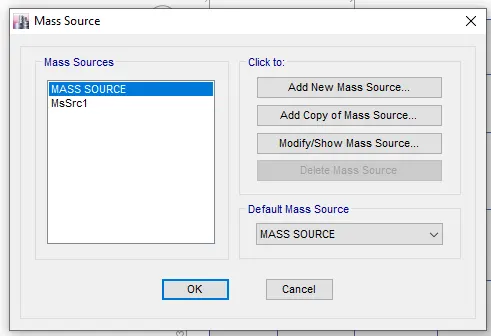
add the mass source
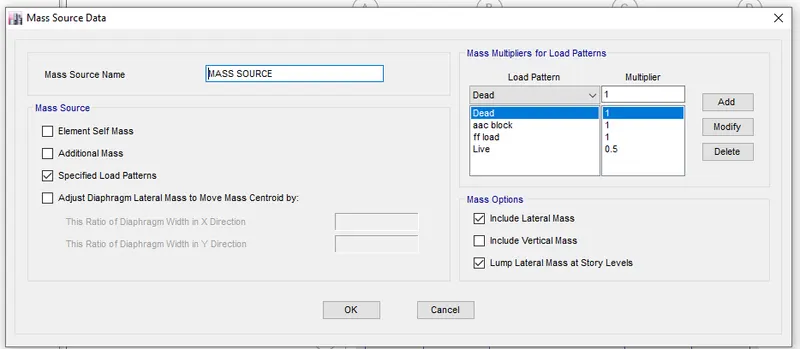
go to define > mass source > add new mass source > select specified load pattern > and add the dead load, live load, floor finish load, seismic load, wall load.
assign the diaphragm to the slabs
go to select > select > object type > floor,
assign > shell > diaphragm > select the d1
the model can be run for the analysis.
check the model for error , if the no error was identified run the model for the analysis.
as per the results from the time period table and the maximum storey drift. If the value from them satidfy the criteria its fine If not the design should be changed, like beam and column dimensions.
The joints and orientation of the frame can be modified anf run the analysis again and check again.
RESULT AND REPORT:
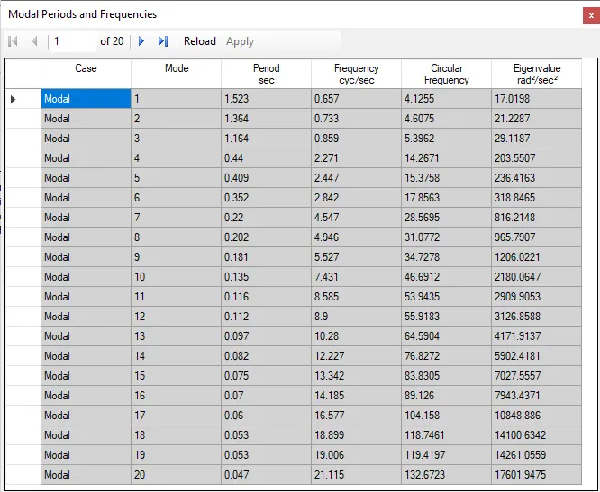
The torsional irregularity , the 1st and 2nd modal value should be greater than the 3rd value which is torsional irregularity. The criteria is satisfied in this case.
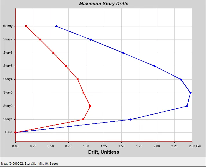
AS PER IS 1893 THE INTER STOREY LIMIT SHOULD NOT EXCEED 0.004,
we have way lesser than that. so the criteria is satisfied.