Drafting of various geometries using Chamfer, Fillet tool in AutoCad
Aim: Drafting of various geometries using Chamfer, Fillet, Arc,Circle tools in AutoCad.
Procedure:
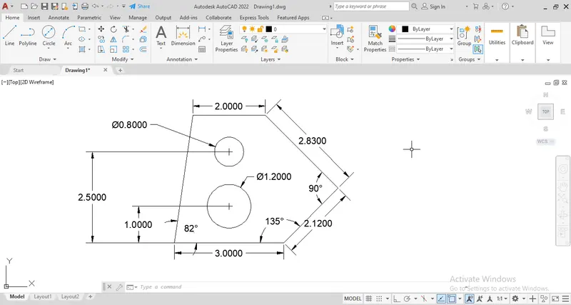
draft 1:
The engineering unit been selected for this dwg, the starting coordinate is chosen at any point on the screen sheet and apply the length (3.000), with the given angle its is fed by the polar coordinate method.Followed up by the other coordinates and complete the outline of the dwg
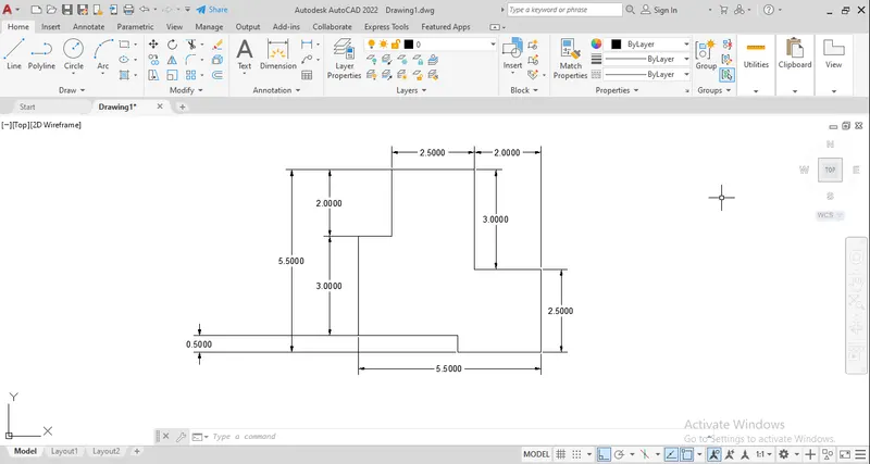
draft 2:
this one is pretty simple, apply the first coordinates at any point of the the screen sheet, and continue to feed the othe coordinates representing the distance of the follow up lines with the polar coordinate method, close the dwg on the end.
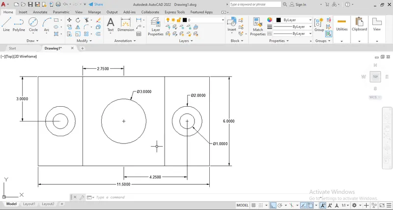
draft 3:
this dwg can be drawn in 2 methods just following the coordinates and draw the outline of the dwg. draw the inner cicle with the reference to the intersecting center point of the circle and the circle is drawn with the given diameter.
And the other method is to draw the on side of the dwg and just mirror it.
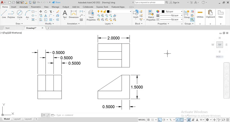
draft 4:
this dwg is the front, top and side view of something.
the given coordinates is feed into the sheet, the three dwg should be equally aligned with the previous dwg.
draft 5:
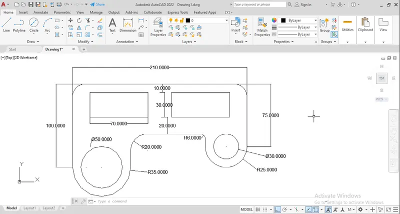
in this dwg the first coordinates is feed into the sheet, the second coordinate goes vertical.
the corners are filled with the fillets with the given radius.
and about the arc and the circle, the line is drawn from the first coordinate horizontally with the given radius and draw a circle 1 and draw the smaller circle with given diameter and trim the part which are not necessary. same steps are followed on the opposite side.
draft 6:
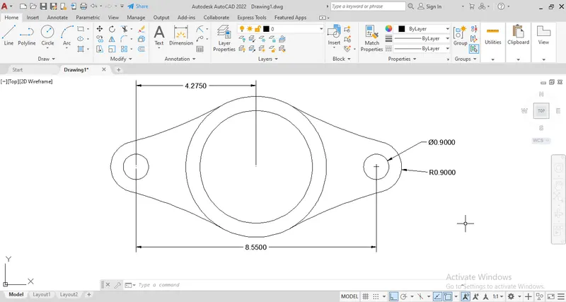
the lie is drawn with the length of 8.55 for the reference to draw the two little circle with the diameter of dia 0.90 and the bigger circle with the radius of 0.90.
the circle is drawn in the mid point of the reference line with the dia of 4 and 5.
the outer circle of the midpoint circle and the 2 endpoint circle is joined with the fillet tool, anf unnecessary part of the circle is trimmed.
draft 7:
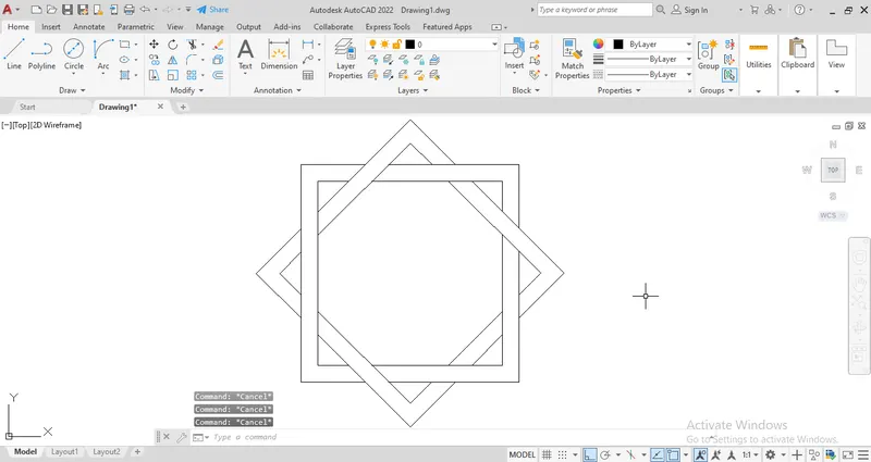
a square is drawn and offset is done for the square.
copy the square next to it, rotate the square to 45 degree and move the square and over lap the two offsetted squares and trim the unnecessary intersection.
draft 8:
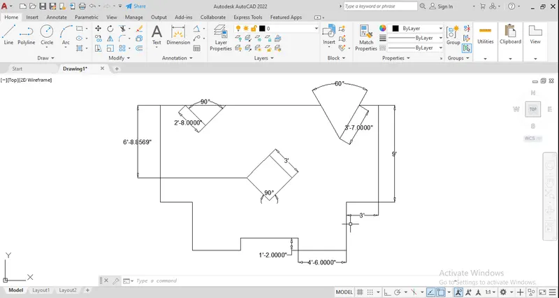
the given coordinates are feed into the sheet with the length of the lines, and the diamond on the inside the outline is drawn with the intersection of the given coordinates.
likewise the angular deviations are drawn with the reference of the given angles.
draft 9:
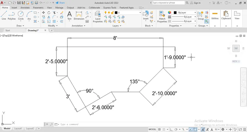
the lines are drawn with the given coordinates and the angular deviations are drawn with the given angles.
draft 10:
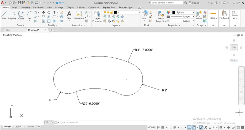
the reference line is drawn with the given length, the circle is drawn in a both end with the given dia.
connect the lower part of the circle with the fillewt tool with the radius of 32'6"
and the top part is connected with the tan, tan, radius circle tool with the radius of 41'8" and trim of the unnecessary part.
draft 11:
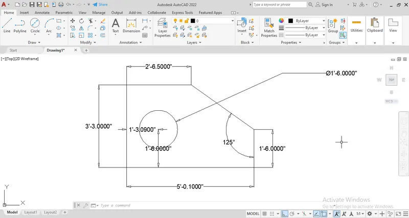
the outline is drawn with the given coordinates and the inner circle is drawn with the center point of the intersection of the 2 coordinates refered for it.
results and report:
All the given drawings are drawn using tht fillet, chamfer, circle and arc tools.