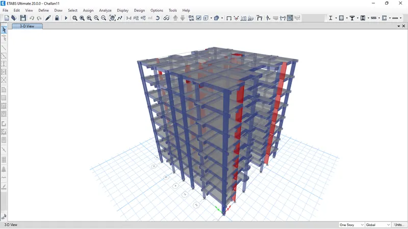
Structural Modelling using Etabs 2018
Aim :-
- To model and analyze G+7 residential plan from given architectural drawings using Etabs 2018.
- To Run a modal response spectrum analysis and check analysis results of the etabs model.
Procedure :-
- Open the ETabs software.
- Click the file menu and choose to create a new model option.
- After choosing a new model a dialogue box will appear as Model Initialization.
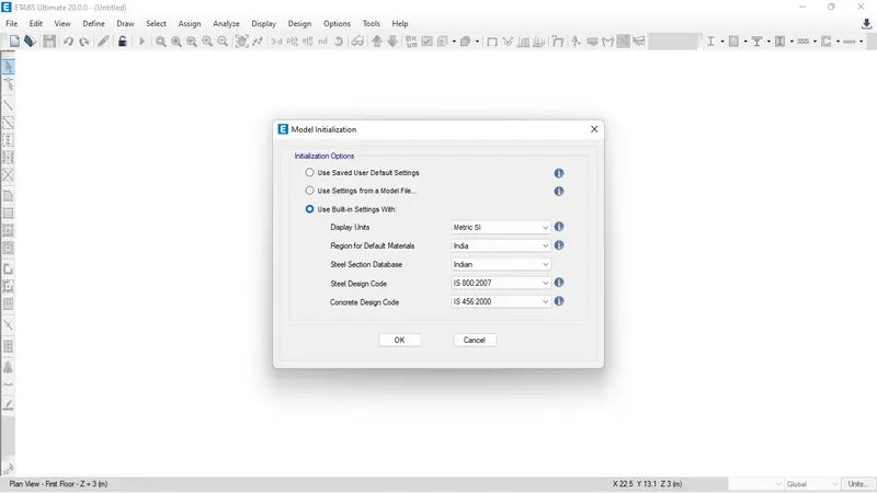
- Choose the built-in settings option and select the display units and codes.
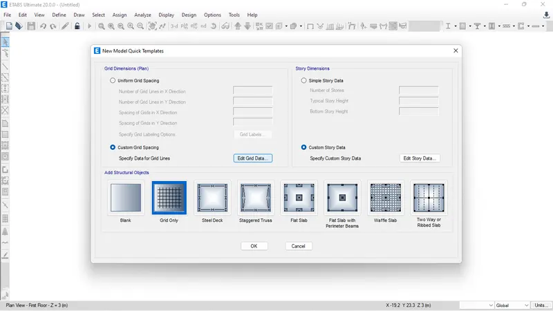
- New dialogue box will appear named New Model Quick Templates.
- Select Custom Grid spacing and custom story data and click okay
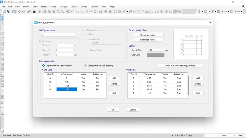
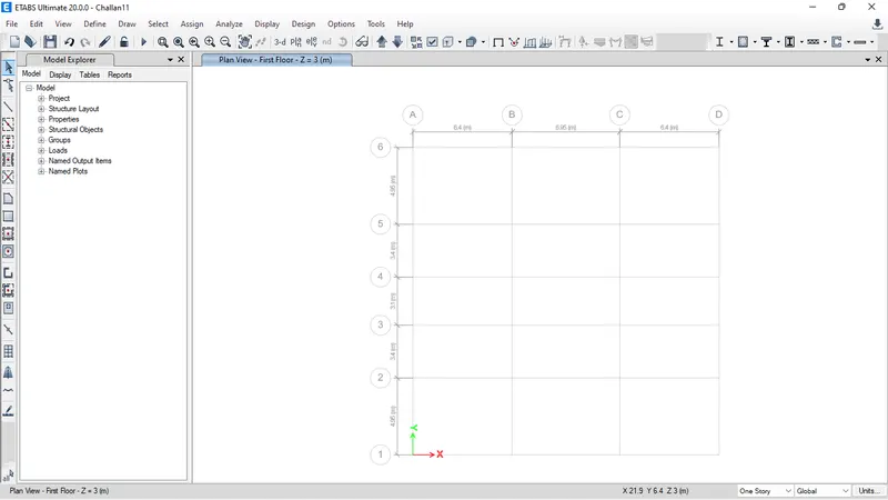
- Now fill grid data in X and Y direction
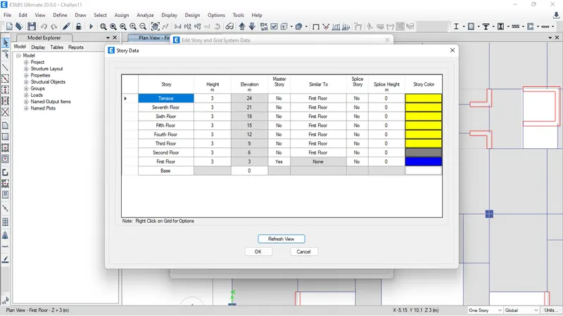
- Now edit the stories add upto 7 story.
- First floor has been labelled as a master storey and all above levels are labelled similar to that.
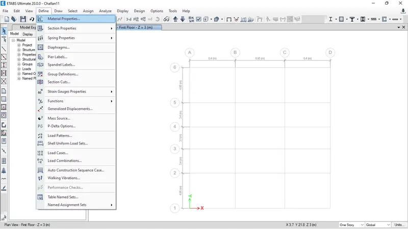
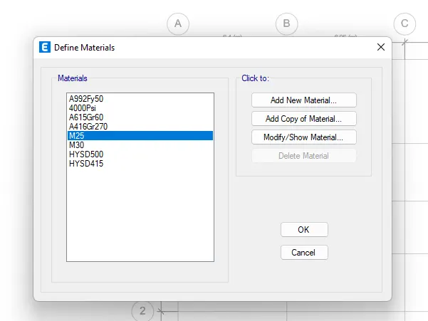
- Select Material properties under define tab.
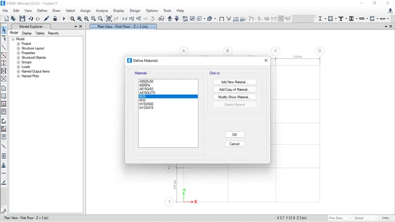
- New dialogue box will appear named Define Materials.
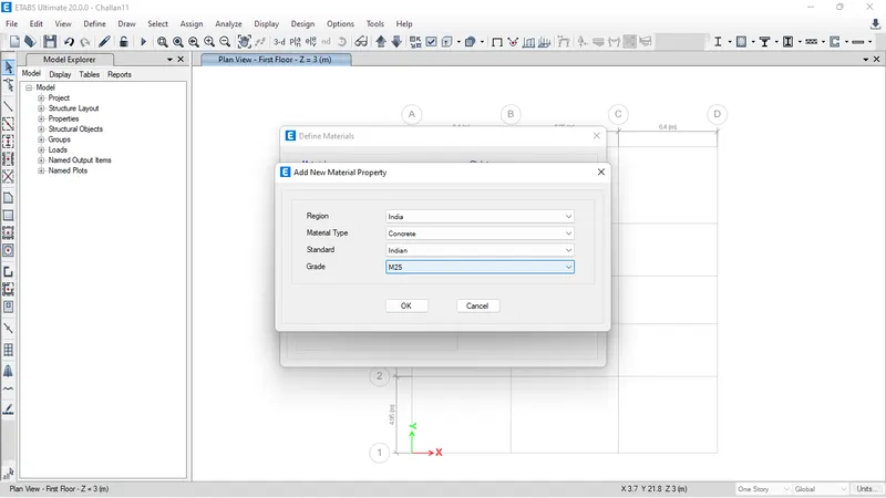
- Click on Add new Material
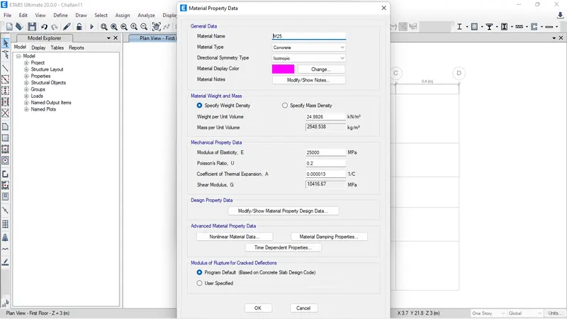
- Now need to add material type as concrete and grade as M25.
- Now we need to check the material property data, as shown below.
- Similarly we can add another concrete material of M30 Grade.
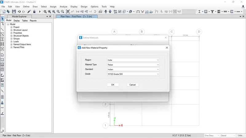
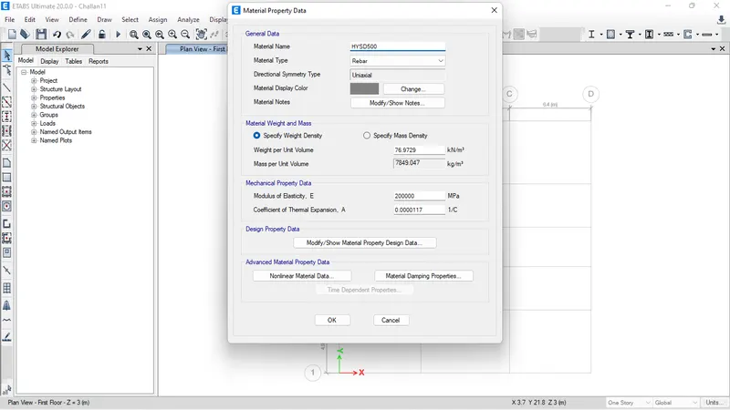
- Now need to add material type as rebar and grade as HYSD 500 and HYSD 415.
- Now we need to check the material property data, as shown below.
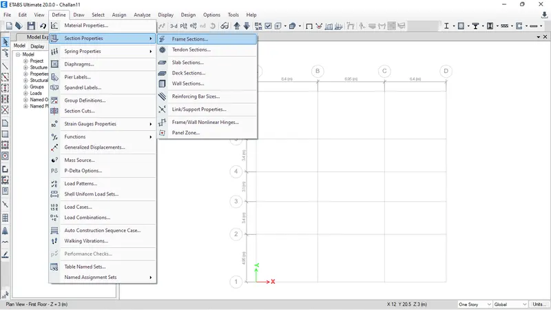
- Now select Section Properties under Define Tab.
- Select Frame Sections.
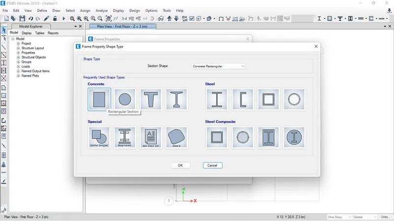
- Select Add new properties in Frame Properties.
- Create a new Property as a beam and input values as 250X450.
- Select Modify/Show Rebar in Reinforcement option.
- Select M3 Design only (Beam).
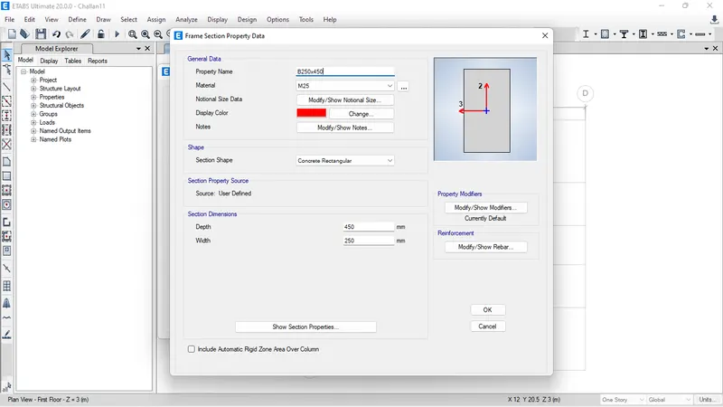
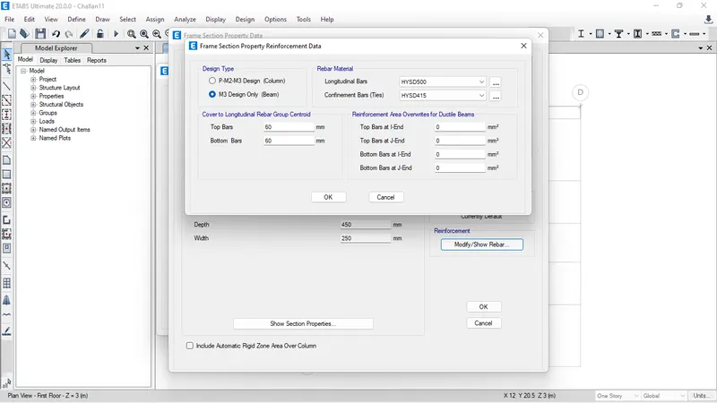
- Similarly we can add beam 300X500
- Now Create a new Property as a column and input values as 400X400.
- Select Modify/Show Rebar in Reinforcement option.
- Select P-M2-M3 Design (Column).
- Select Reabar as HYSD415.
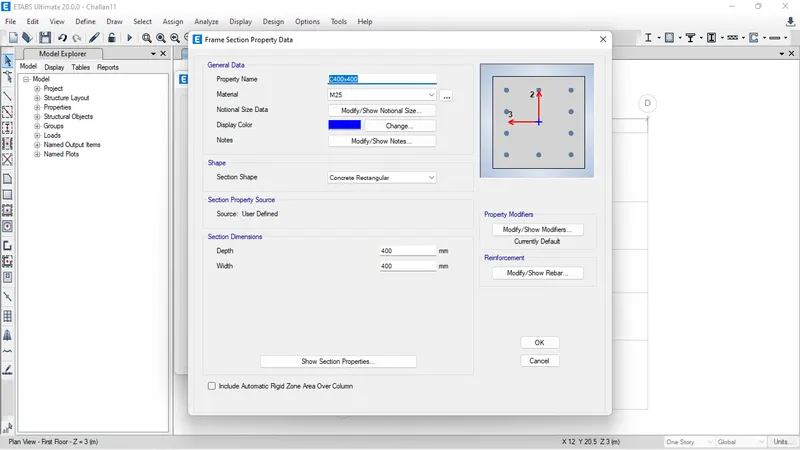
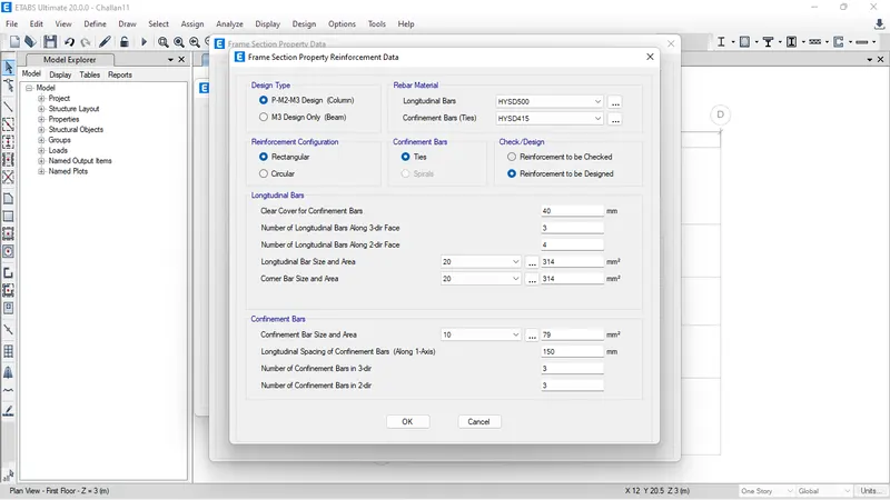
- Similarly as above Create a new Property as a column and input values as 400X650.
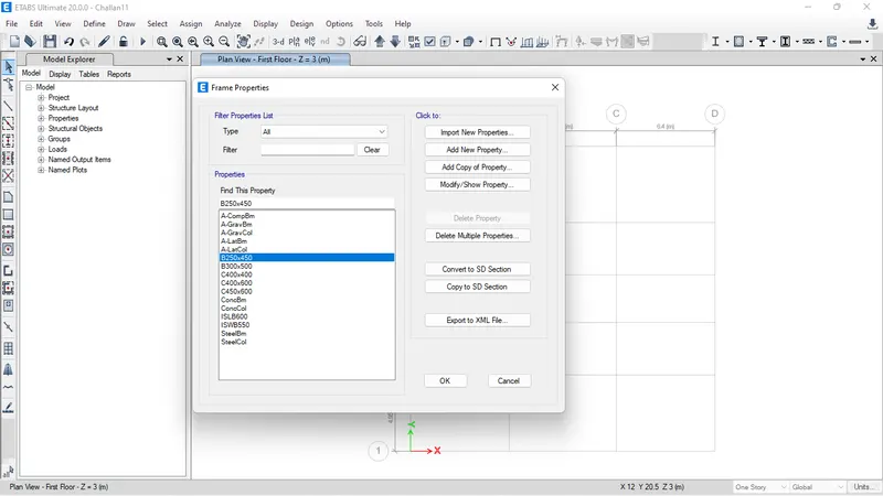
- Now select Section Properties under Define Tab.
- Select Slab Sections.
- Select Add new properties in Slab Properties.
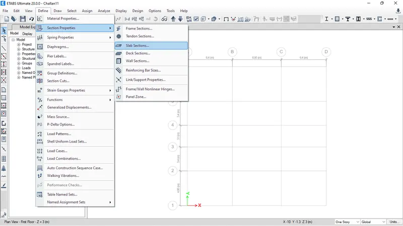
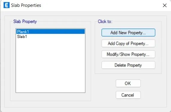
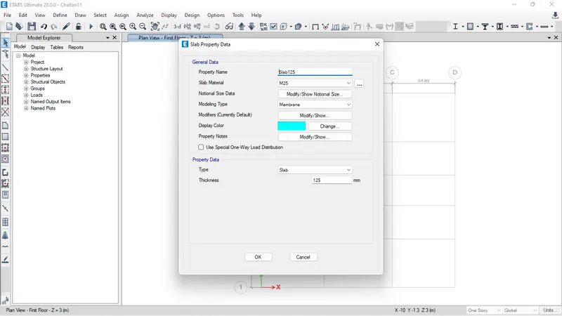
- Using the membrane properties, slab size 125 mm has been added to the list.
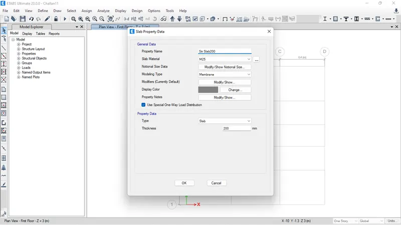
- Using the membrane properties, slab size 200 mm has been added to the list for staircase.
- Now we have to add Wall properties in wall property data.
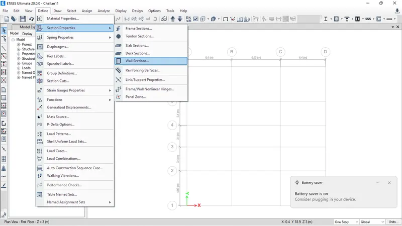
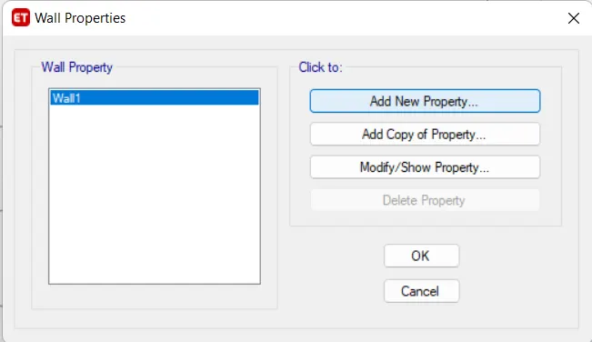
- Now add the wall data as thickess of the wall as 250 mm, Material- M25.
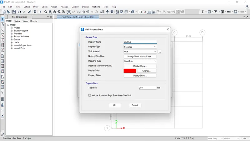
- Similary add another wall property data as thickess of the wall as 300 mm, Material- M25.
- Now Draw columns
- Choose the size of column
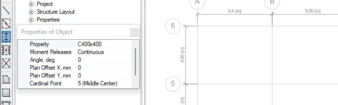
- take the cursor at grid point and left click column will be drawn
- before that make sure to select 'All story'
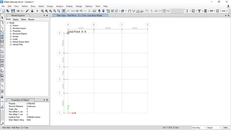
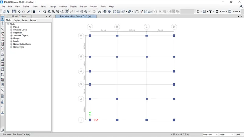
- Columns are Successfully added to the structure.
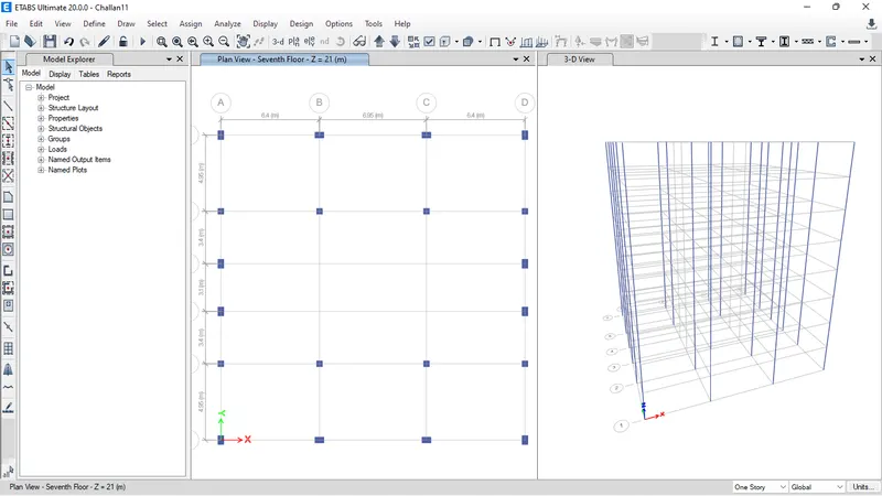
- Now Draw the Beams.
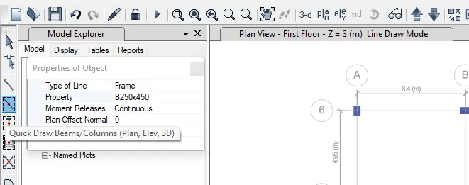
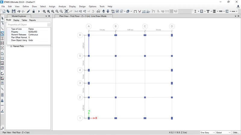
- After adding all the beams
- Next we add the shear walls in required locations in longitudinal building.
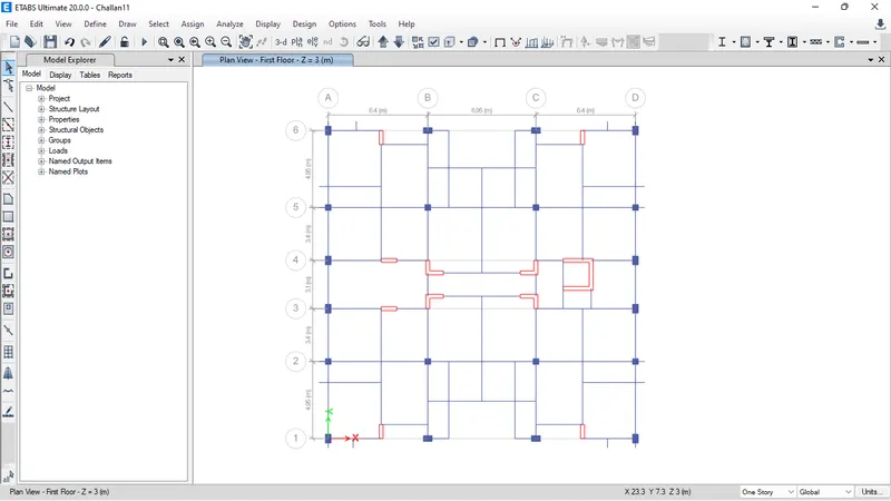
- Now Draw the Slab.
- Draw slab of size 125mm thickness, Draw slabs with quick draw floor/wall keeping all the stories on.
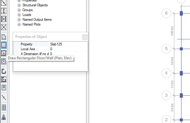
- Slabs are Successfully added to the structure.
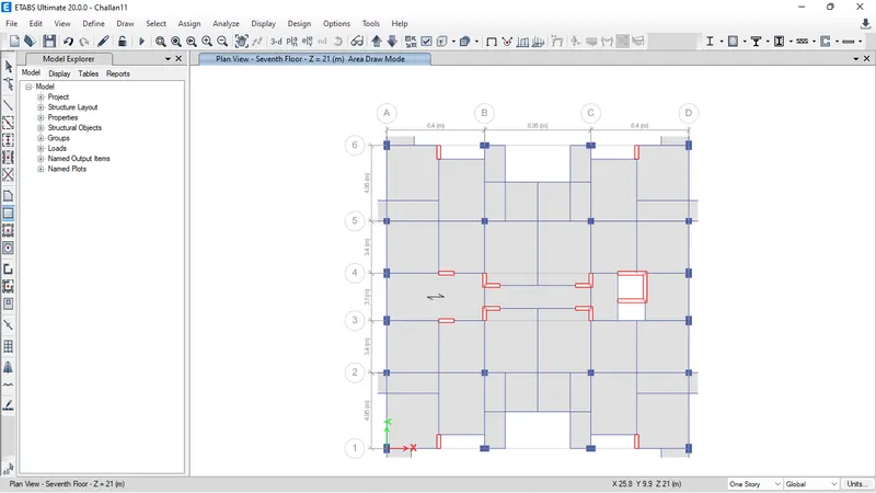
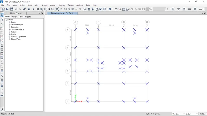
- Now we go to base plan and select all the joints.
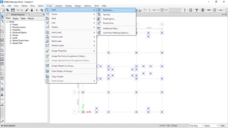
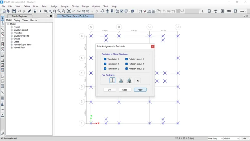
- Now we select the Restraint from joint option, as shown below.
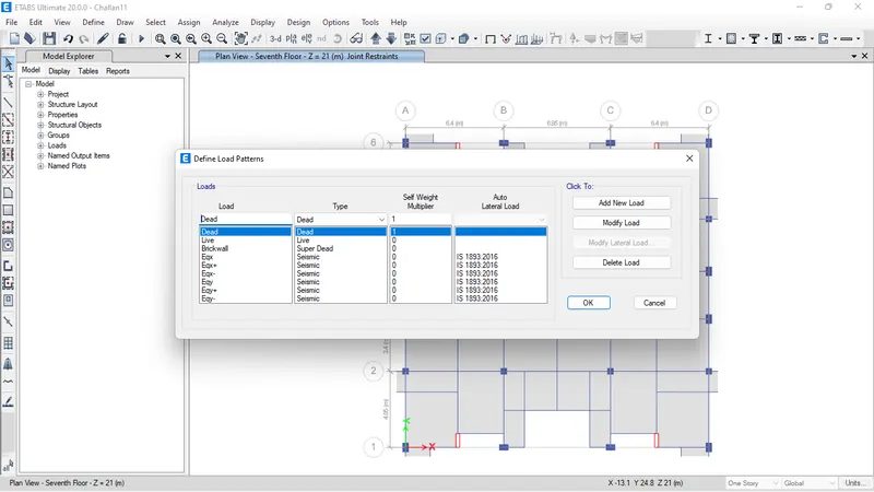
- Now define the Load patterns.
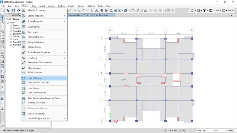
- Click on the define tab and click on load patterns.
- Define the loads like dead load, live load, brick load, earthquake load in X direction and same loads in Y direction also.
- Mention IS codes of respective loads.
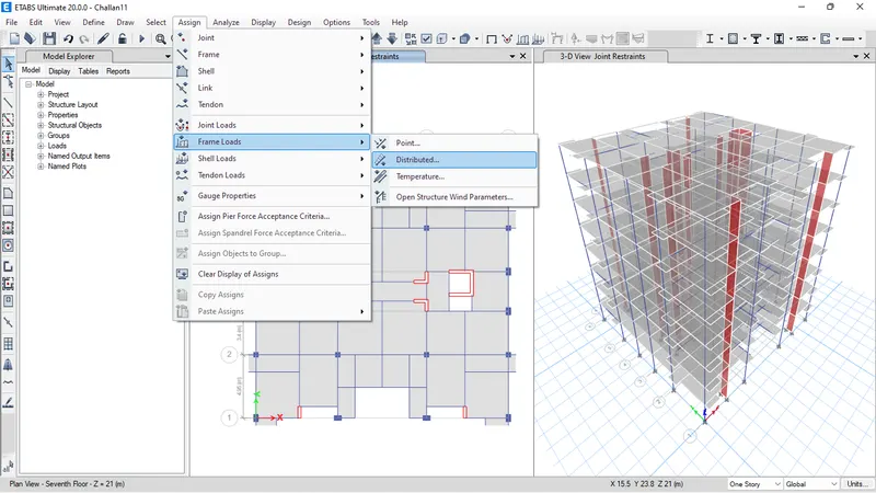
- Next we need to select the distributed load from the frame loads.
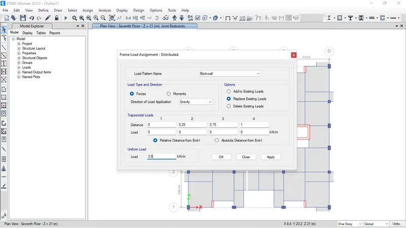
- Then after the new tab will appear, in that case we select load pattern as Brickwall and we take uniform load as 3.5 Kn/m an then apply.
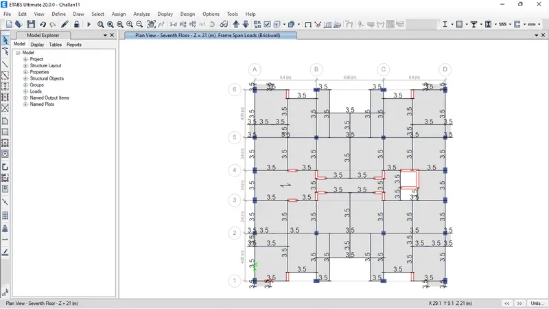
- Next we have to click on assign option and then select shell loads and select Uniform option.
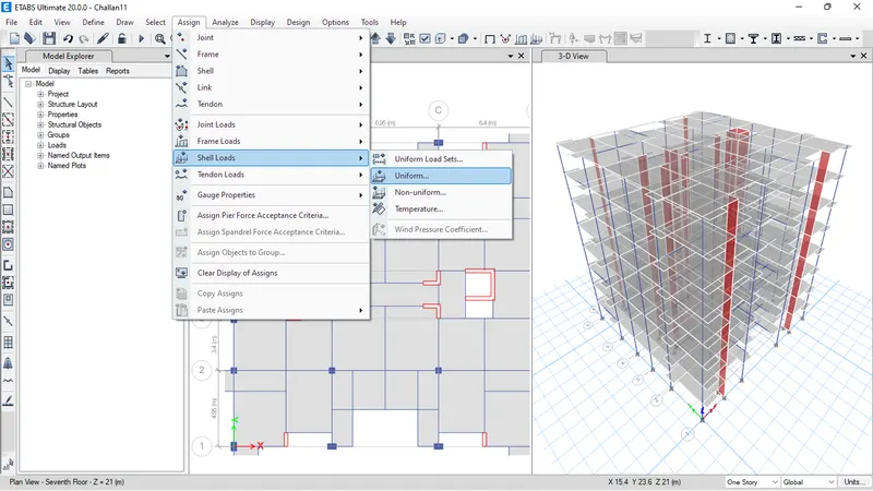
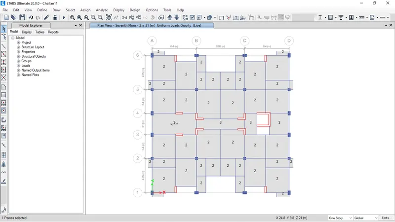
- Here we apply 3 Kn/m2 live load for the staircase portion, verandah and liftcore area and rest of the portion of slab 2Kn/m2 live load
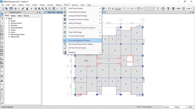
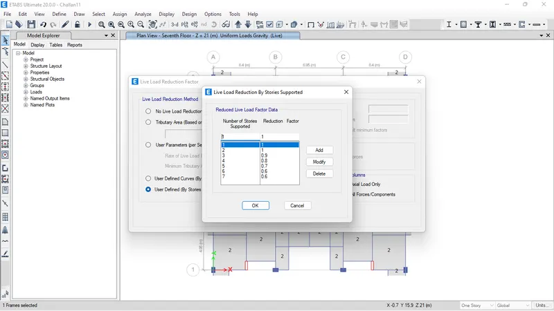
- Next we add live load reduction factor from the design option.
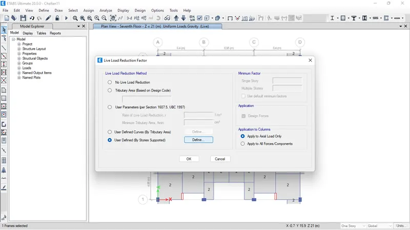
- Now add the reduction factor as decrease of 10%from 1st to 7th floor.
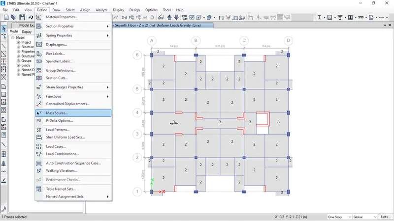
- Now go to Mars Source from define tab.
- Modify the mars source and tick mark the required loads.
- Add load patterns and assign the model.
- Insert the dead load as multiplier to 1, live load as multiplier to 0.25 and wall load as multiplier to 1.
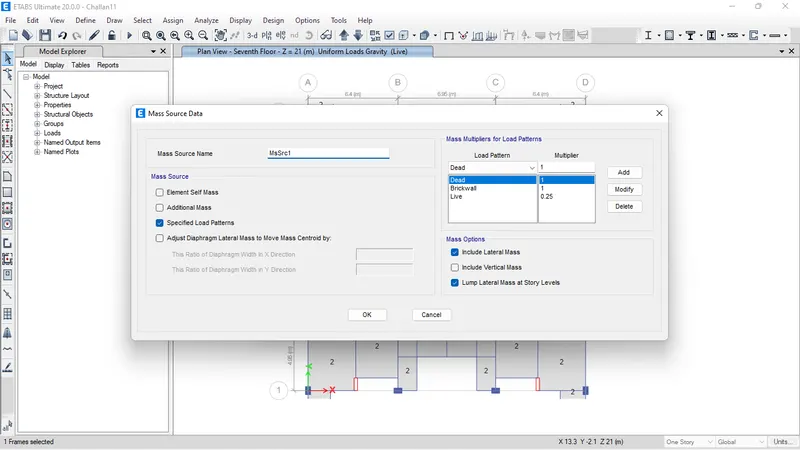
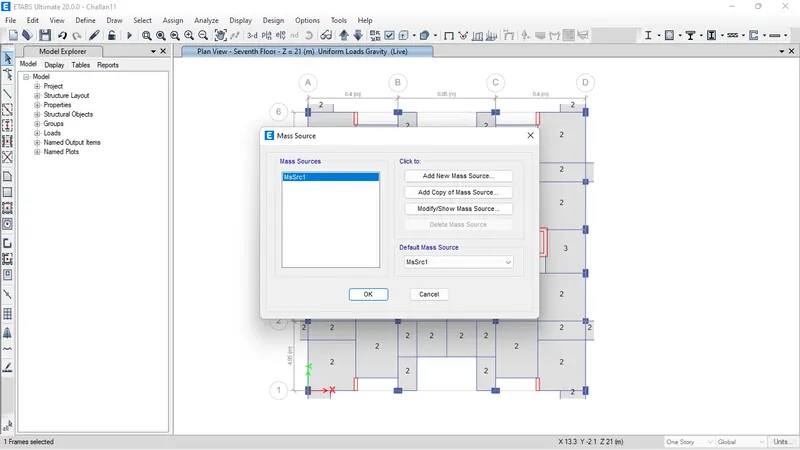
- Mars source is been added successfully.
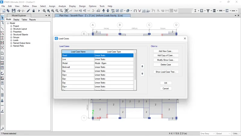
- Now go to Load cases in define Tab.
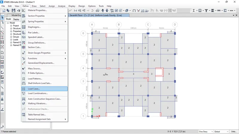
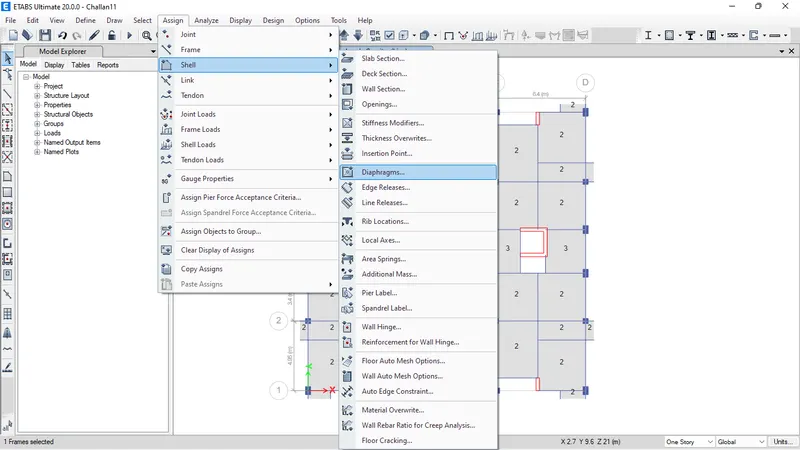
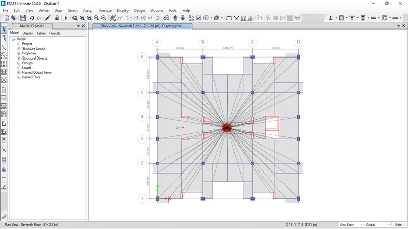
- Now create the Diaphragm by going to the assign tab then shell and select diaphragm.
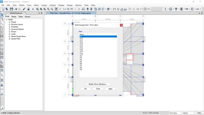
- Next we have to select the pier lable from shell option.
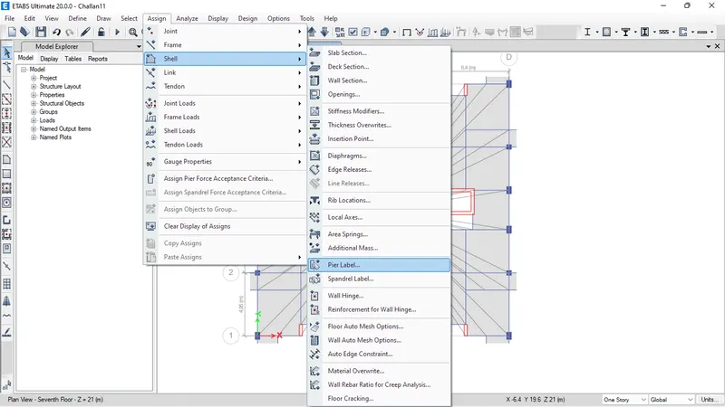
- WE have to assign the names for the shear wall.
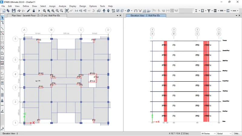
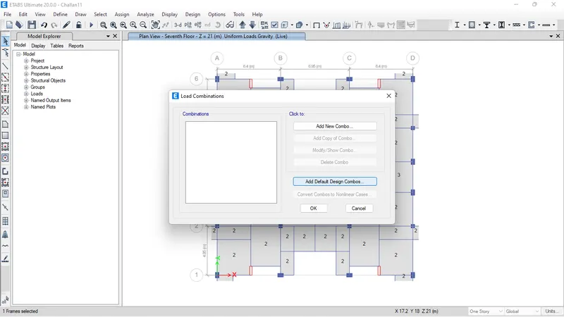
- Now go to Load combinations in define Tab.
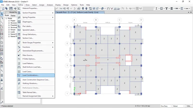
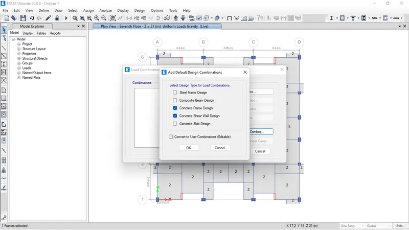
- Select add default design combos.
- Select concrete frame Design.
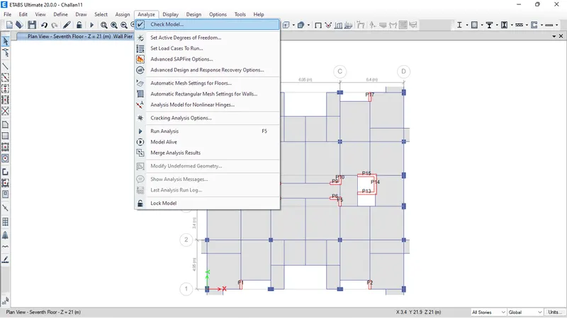
- Next we need to check the Model.
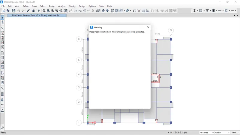
- After the model is checked, it will show us No warning.
- Now select the response spectrum from Functions option in define Tab.
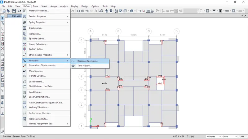
- We choose IS 1893:2016 from choose function Type and click on Modify/Show spectrum option.
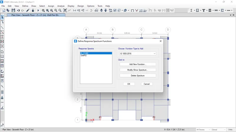
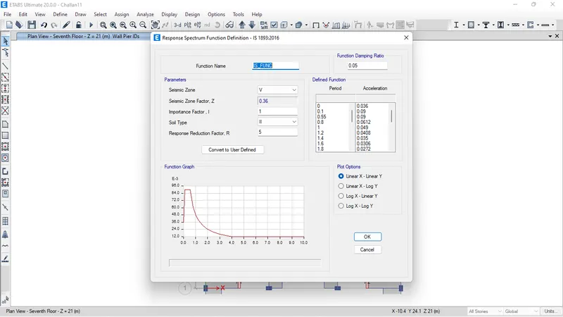
- Now go to Load cases in define Tab.
- Add new case.
- RSx and RSy and select case type Response Spectrum
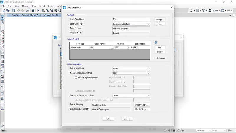
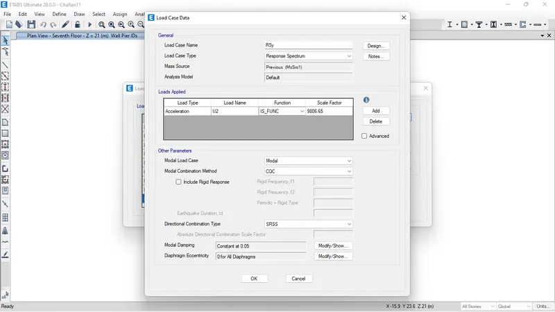
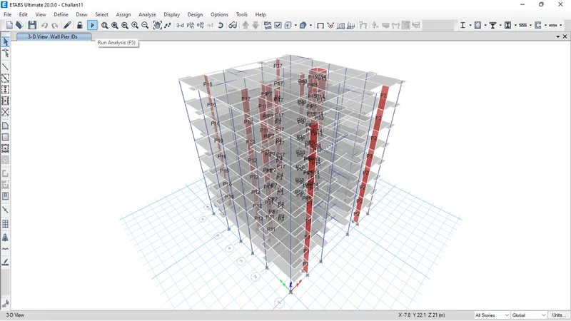
- Analyse the model using analyse option then click on check model the modelled structure is verified without errors and warnings.
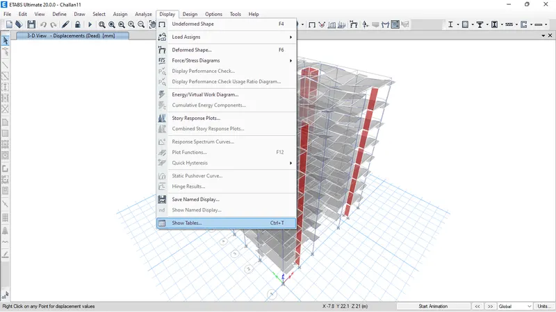
- Now click on display -> show tables -> Analysis result structure output -> Base Reactions
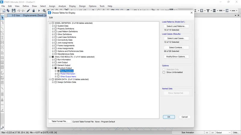
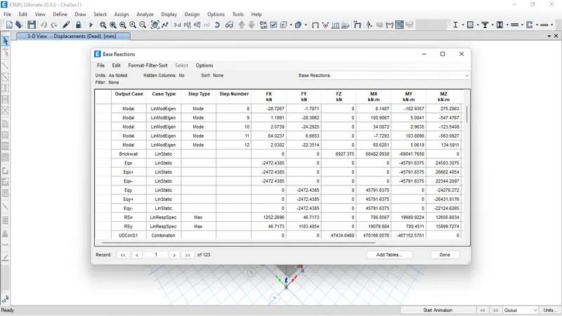
- We have to check EQ should be close to the RS , We should calculate the
(EQ/RS X Scale factor of Response Spectrum)
- Now substituting the value from the table ,
At X- direction = ( 2472.4305 / 1252.2696 ) X 9806.65
= 19361.85
At Y- direction = ( 2472.4305 / 1183.4854) X 9806.65
= 20487.164
- Now we put above value as scale factor for Response Spectrum at X and Y direction.
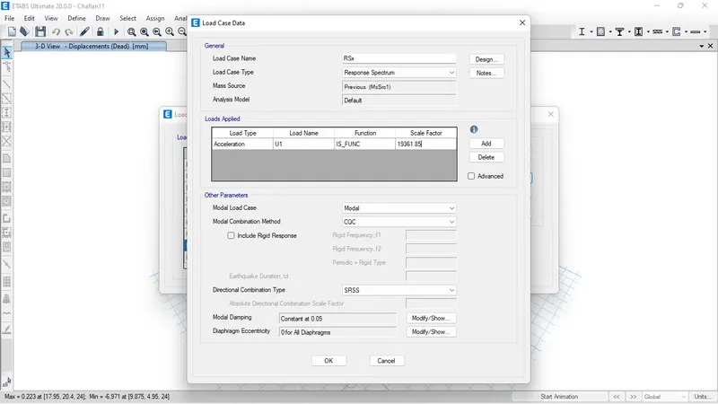
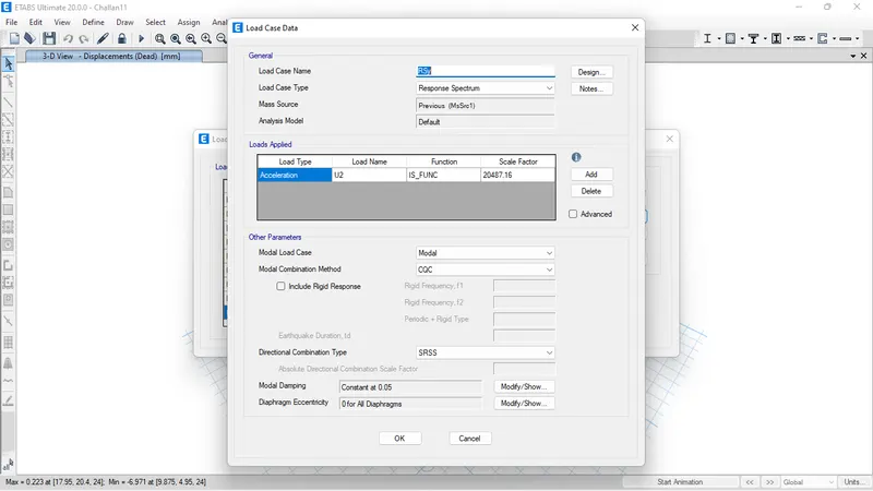
- After that run analysis again and see base reaction
- value of RSx and RSy should be approximate to value of Eqx and Eqy
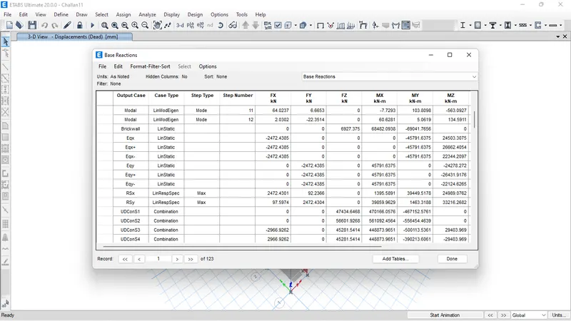
- Now click on display -> show tables -> Analysis result structure output -> model information -> model periods and frequencies.
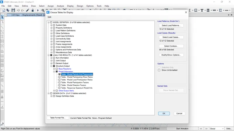
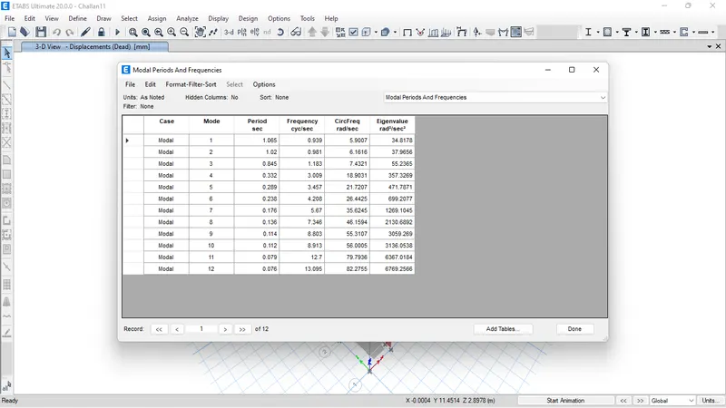
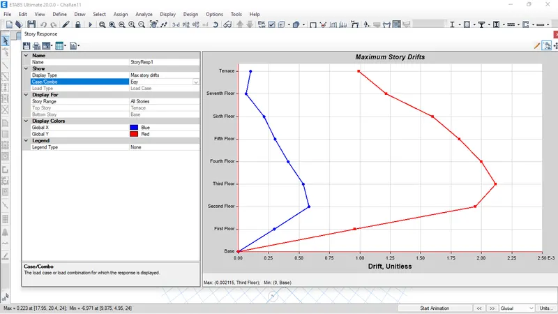
- Select the Story Response Plot from Display option.
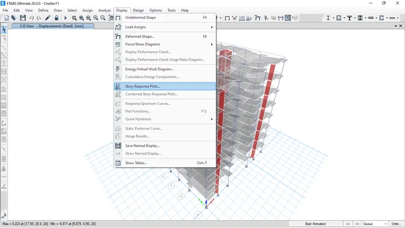
- Story Response for maximum Story Drifts for x and Y direction is as per following.
X- Direction :-
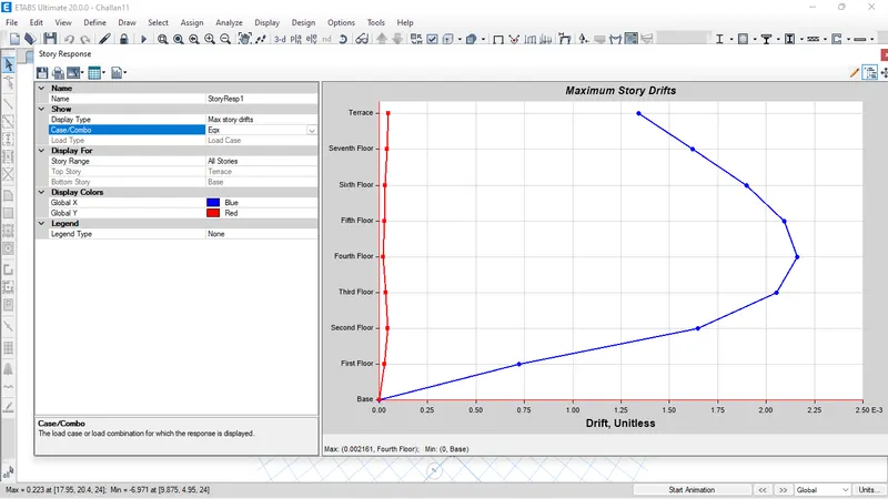
Y- Direction :-
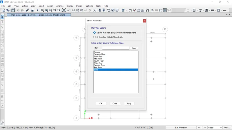
- Next we open the Base floor in Plan view.
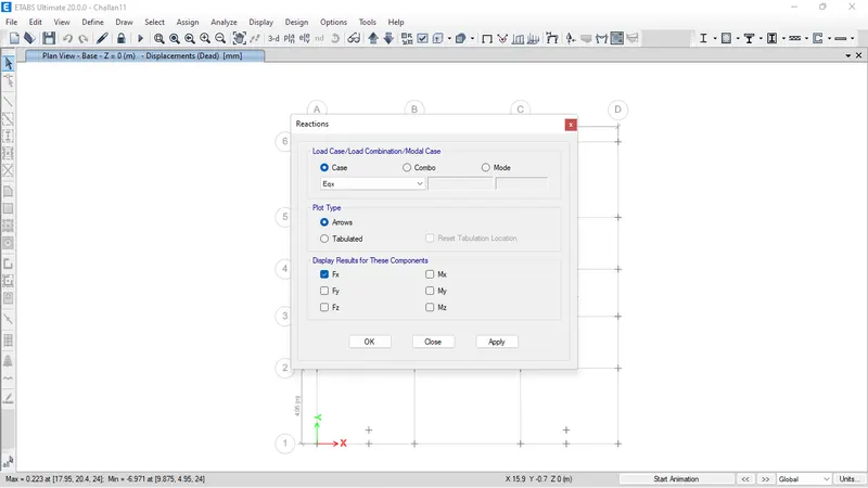
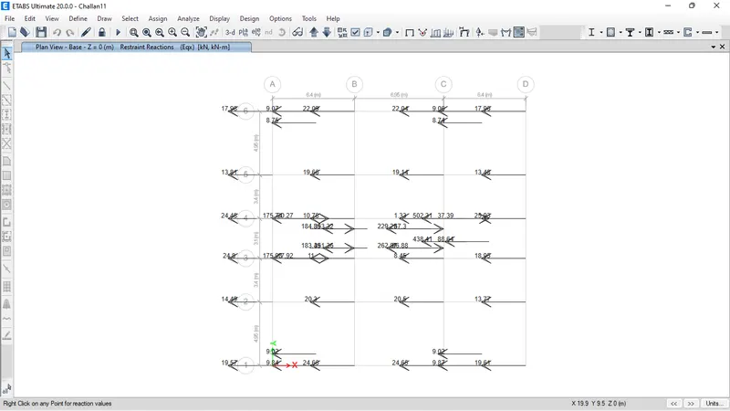
- We have to open Reaction tab, we select the earthquake load towards in X-direction in load case.
- When we divide base shear taken up by shear wall divided by total base shear of Building will get % of shear forces taken by Shear Wall.
- And if that is less than 80%, then the more shear walls we need to add to the structure.
Result :-
- Modeled and analyzed G+7 residential plan from given architectural drawings using Etabs 2018.
- Run a modal response spectrum analysis and check analysis results of the etabs model.