Structural Modelling using Etabs 2018
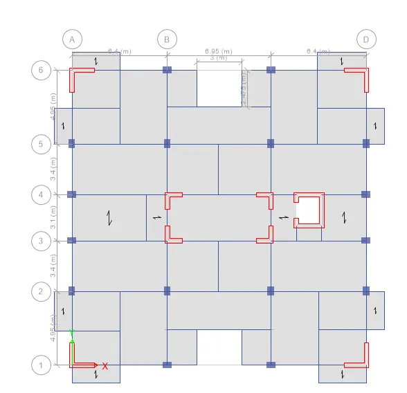
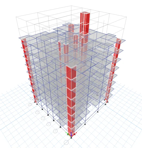
The architectural drawings for a G+7 residential building in zone 5 has been provided. The floor plan is the same for all 7 floor levels. Possible column positions have also been provided. Conceptualize a framing plan layout and then model the building in Etabs. The following architectural drawings have been provided:
- Typical floor plan – The location and thickness of the brick walls and the use of the
space (for estimating live load) can be obtained from this plan - A building section through the staircase and lift core is provided
- Parking layout in the ground floor – the column/shear wall arrangement must not
obstruct entry/exit of vehicles.
The following loadings are to be taken into account: - Brickwall made of AAC blocks
- Finishes – floor tiles of 75 mm thickness
- Live loads as per IS 875 part 2
- Water tank of 20 KL above the staircase at Mumty level
- Lift Machine room at mumty level above lift core
The structural model must comply with provisions of IS 1893 and IS 13920.
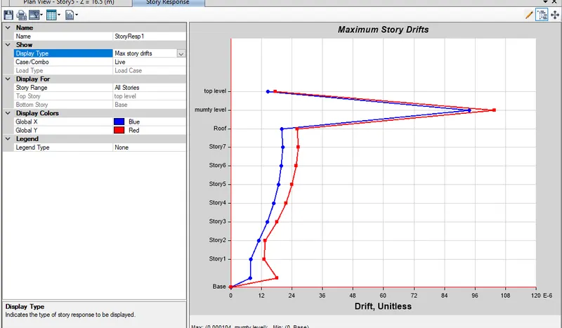
Run a modal response spectrum analysis and check analysis results of the etabs model for inter-storey drift requirements, vertical & planar irregularities, minimum shear wall requirements,maximum axial load ratio for column and shear walls, effective moment of inertia for beams
and columns etc.
Please note that the column positions shown in the architectural typical floor plan are only to provide an initial starting point for modelling. Participants will have to change its size, introduce shear walls, and add new vertical elements after running the analysis. You will have to run the analysis multiple times until a structural model is obtained that meets structural code requirements without compromising architectural functions. Also, there is no one ‘correct’ structural system for this challenge. There can be multiple possible solutions for this problem.
Aim:- To analyze and design the given building followed by details and tallying the output with given specifications.
Procedure:-
Step-1(grid,storey,material properties)
- Edit grid system with the help of architectural drawing modify the grids here last grid pointt stands as 0 in X&Y axes
- Edit storey system by using edit grid all grids will be similar to storey1 except roof.
- Define-materialproperties here i choose M30 and other values are default
- material type-rebar-Fe500,choose for shear reinforcement Fe415
- Define-section properties-beam size-400mm X 500mm,column-450mm X 600mm,Slab-150mm,Shearwall thickness-300mm
- The above sizes are assumptions only because analysis is the iteration process.
The minimum dimension of column size is 8 times of the longitudinal bar.
For beam:-
- Change the property name
- Material
- mention width,deoth,property modifiers
For concrete:-
Reduce MOI for 2&3 from 1 to 0.35 as per codal provisions because the effective MOI will be taken but the gross MOI edit torsionl constant from 1 to 0.001
For reinforcement:-
Edit design type beam And here select the longitudinal bars to HYSD500 only.
Cover the longitudina rebar group centroid:-
We need to mention here the cover from centroid to rebar so we need to consider 55mm to 60mm in the lieu of 25mm to 30mm
For column:- here size-450mm X 600mm
Everything as like as beam but in property modifiers
For concrete:- Reduce MOI 2&3 from 1 to 0.7 as per codal provisions
For reinforcement:- Change design type to column in longituinal bar for 10mm 1 longitudinal bar
For confinement bars According to IS:13920 Clause of confinement for 3direction3 and 2direction2
For slabs:- Here 150mm Remember that modelling type of slab is always MEMBRANE.
For walls(shear):- Here 300mm Remember that modelling type of shear wall is SHELLTHIN
Step-2:-(Assigning elements)
- Start assigning with columns
Assigning by selecting quick draw columns and then the columns will automatically created at junctions (Set all stories at bottom)
To rotate the column select it
and the assign-Frame-local axes-rotate to 90
2. To add beams quick draw beams and select the places (All stories should be at bottom)
Secondary beams :- by using reolicate option we can create secondary beams.
To break joints select the beam-edit-editframes-divide frames-break at frame joints.
To draw perpandicular offset beam (from center of beam)
Draw-snapoptions-tick the perandicular projections
3. Shear wall
In zone-5 minimum length of shear wall is 1.5m and thickness 0.3m.
Add the shear walls in all corners and at the openings
Here we have 8m^2 of shear wall because of 2% in gross area.
When we need to add the shear walls we need to delete the columns at that place.
Go to draw walls and select the corner & type of wall and draw it.
TO draw shapedshear wall
Draw-drawwalls-choose the shape-enter the dimensions-if we need can mirror ir by using reolicate by picking two points option.
4.For floors
To draw slab b/w 4 corners use quick draw floors
At the place of stair case the one way slab is there (so edit the orientation of slab by using edit shell)
Assign-shell-local axis-rotation 90-close
Add projections of the slab as per architectural drawing.
When we assign slabs just deselect the base level we dont need base slabs.
5.Foundation
select joints-assign-joint-restraints-fast restraints-fixed symbol-apply-ok
Step-3:-(load assignments)
- Gravity loads:
On the roof there is no brick wall lo
ads keep the arch.dwg against model to cross checking
Select the beams
Assign-frameloads-distributed loads-load patterns(brickwall load)-add load as 5kn/m
By using perspective toggle we can see individual floor load assigning patterns.
If any indications merged use the set view options.
Live load:
For live loads refer IS:875 part-2-1987 table-1
here avg live load is 2.5 kn/m^2
select the area similar stories and assign -shell loads -uniform-load as finishing 2.5kn/m^2(based on floor material used)
Is:875:part-2-1987 (3.2.1)
Assign-shell loads-uniform-load-1.5n/m^2
Live load reduction factor:
For high rise live load will vary with the time and place so we must consider this.
For 3 floor 10% should be considered 0.1 but after that it will vary.
Design-live load reduction factor-user defined by stories support -modify for one floor-1,2-1,3-0.9,4-0.8,5-0.7,6-0.6,7-0.6,8-0.6,9-0.6
it should nnot less than 0.6
Earthquake loads:
To add this lad we need to know the time period of building in X &Y directions
Is:1893-part1-2016
7.6.2
c) All other buildings
T= 0.09h/sqrt d
where:
d=base dimensions of the building at the plintyh level along the considered direction of earthquake shaking in M.
h= height of the building
To find height of the building go to edit stories
For d take round figures
h=30m,d=20m
T= 0.09*30/sqrt 20
T=0.6sec
Add earthquake loads to model in define-load patterns.
Generally 6 types of loads will be added EQx,+EQx,-EQx,EQy,+EQy,-EQy
from codal provisions of IS:1893-2016
Then click on EQx - modify lateral load except X direction untick remaining
Response reduction factor - 5 for dual system
Response reduction factor - 4 for shear system only
Time is changes based on shear walls too.
seismic zone factor-Z
per code -0.36
site type- zone-ii (from soil type)
Is:1893-part-1:2016 for imporatnce factor table-8
importance factor for below
200 people -1
above 200-1.2
Time period y = 0.6sec
For EQx+ -Direction X+ remain unselect follow the steps before for all 5 loads
Mass source:
define - mass sourse- usually dead load is 25% of live load
So add dead load multiplier as 1
live load multiplier as 0.25
Is:1893-2016-part-2 table -10clause 7.3.1
Live load upto 3kn/m^2 is 25,above 3kn/m^2 is 50
so here it is 25.
Diaphragm:
Select-object type-floors
Assign-shell-diaphragms-D-apply-ok
Pier labels:
For every shear wall there should be an unique pier label
Select shear wall by using elevation view and maksure that you are in all stories while you add from plan view.
after selection of shear wall
Assign-shell-pierlabel-assign the name
Load combinations:-
Define-load combinations-add default combos
concrete frame design -ok
concrete shear wall design-ok
convert user combination (editable)-ok
Based on codes program generates load combintions
create 3 files-
gravity loads - 0.35-1
Earthquake loads
Response spectrum
Step-4:-Model analysis
Model analysis is default mode
Analyze-set load cases -run/dont run of cases
calculate diaphragm center-ok
Analyze
last part of modelling is the iterative process we must reach the norms of IS:1893-2016-is func
pattern according to is:1893
Load case-Add new-load case ame(RSx)-load case type (response spectrum)-load applied(add)-acceleration-U1-Is func-9806.65(scale factor)-Add RSy as above
7.7.5.3 of IS:1893 com bination modes
i) CQC
ii) SRSS
Define-load combinations-add response spectrum-load combinationsby refreshing it.
run the analysis
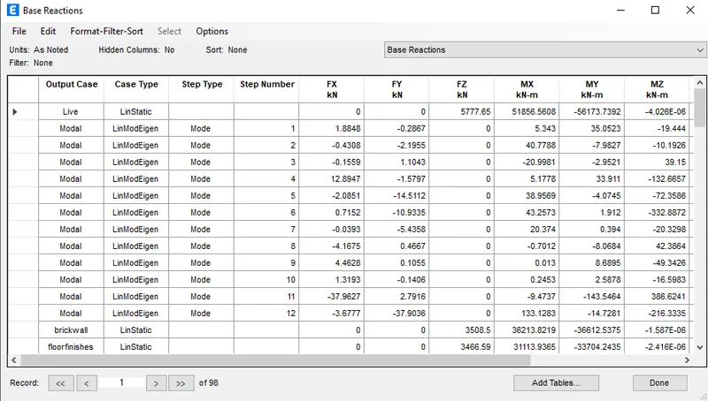
Display-show tables-structure output-base reaction
base shear in response spectrum is atleast equal to EQx,EQx+,EQy- base shear
Is:1893-2016
Clause-7.7.3:
Dynamic analysis may be performed by either the time history method or the response spectrum method when either of the methodsis used,the design base shear Vu is estimated shall not be less than the design base shear Vu bar calculted using a fundamental period Ta where as Ts as per 7.6.2
In my case
RSx = 812
RSy = 788
EQx,EQ+,EQ- = 4215
Scale factor for response spectrum
4215/812 = 5.19
9806.65*5.19 = 50905.21
Add this scale factor for RSy
Re run the analysis
Display-show table-response spectrum base shear is equal to EQx,EQx+,EQy- base shear
equal scaling factor used for scaling as IS:1893-part-2-2016.
Model images and results:-
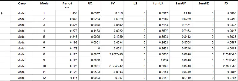
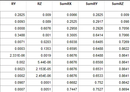
Result:- Finally i got to know about how to analyze a building in etabs.