Drafting of various geometries using Chamfer, Fillet tool in AutoCad
1)
Aim:- To construct the given drawing by using autoCAD sofware.
Procedure :-
1.By using line command i entered the straight line.
2 By using line command and then by using rotating comand i joined the l shape with the previous section.
3.By using oject snap option i created the circles at the given distance.
4. in units i changed the mode into decimels and precission also.
5. Provided drawing is constructed by auto cad as given below.
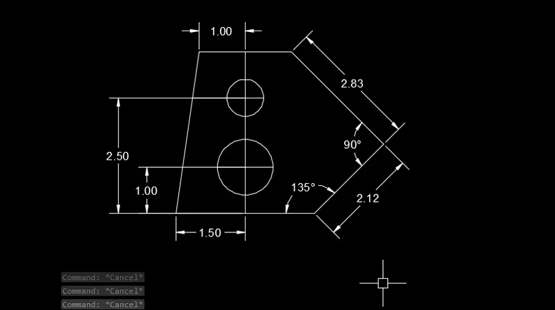
result:- finally i got the result by using auto CAD.
2.
Aim:- To construct the given drawing by using autoCAD sofware.
Procedure :-
1.By using line command i entered the straight lines.
2 By using polar coordinate method and then by using rotating comand i joined theinclined lines with the previous section.
3.By using oject snap option i created the angles at the given distance.
4. in units i changed the mode into architecture and precission also.
5. Provided drawing is constructed by auto cad as given below.
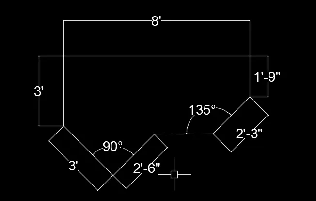
result:- finally i got the result by using auto CAD.
3.
Aim:- To construct the given drawing by using autoCAD sofware.
Procedure :-
1.By using line command i entered the straight lines.
2 By using polar coordinate method and then by using rotating comand i joined theinclined lines with the previous section.
3.By using oject snap option i created the circle at the given distance.
4. in units i changed the mode into engineering and precission also.
5. Provided drawing is constructed by auto cad as given below.
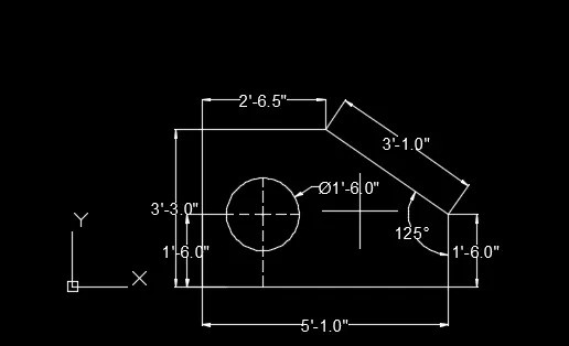
result:- finally i got the result by using auto CAD.
4.
Aim:- To construct the given drawing by using autoCAD sofware.
Procedure :-
1.By using line command i entered the straight lines.
2 By using abosolute coordinate method and then by usingretangular coordinate method i joined theinclined lines with the previous lines.
3. in units i changed the mode into decimel and precission also.
4. Provided drawing is constructed by auto cad as given below..
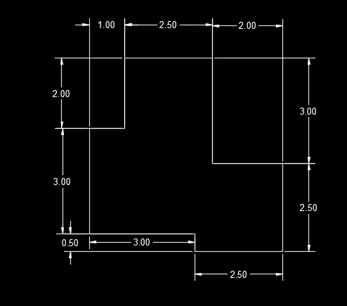
result:- finally i got the result by using auto CAD.
5.
Aim:- To construct the given drawing by using autoCAD sofware.
Procedure :-
1.By using line command i entered the straight lines.
2 By using polar coordinate method and then by using rotating comand i joined theinclined lines with the previous section.
3.By using oject snap option i created the angles at the given distance.
4. in units i changed the mode into decimel and precission also.
5. Provided drawing is constructed by auto cad as given below.
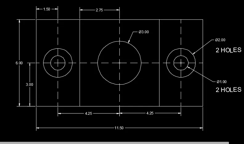
result:- finally i got the result by using auto CAD.
6.
Aim:- To construct the given drawing by using autoCAD sofware.
Procedure :-
1.By using line command & rec i created rectangle
2 By using line command and then by using offset comand i created the shapes with the previous section.
3.By using oject snap option i created the objects at the given distance.
4. in units i changed the mode into decimels and precission also.
5. Provided drawing is constructed by auto cad as given below.
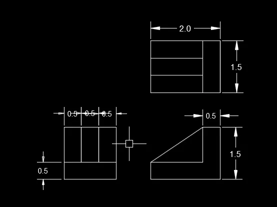
result:- finally i got the result by using auto CAD.
7.
Aim:- To construct the given drawing by using autoCAD sofware.
Procedure :-
1.By using line command & rec i created rectangle.
2. i created arcs by using fillet option.
3. By using line command and then by using arc comand i created the shapes with the previous section.
4.By using oject snap option i created the circles at the given distance.
5. Provided drawing is constructed by auto cad as given below.
-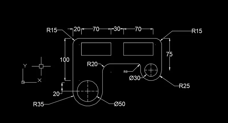
result:- finally i got the result by using auto CAD.
10.
Aim:- To construct the given drawing by using autoCAD sofware.
Procedure :-
1.By using line command & rec i created rectangle.
2. i created angular rec by sing rotating command.
3. By using line command and then by usingoffset command i created the shapes with the previous section.
4.By using oject snap option i placed at the positions given at the given distance.
5. Provided drawing is constructed by auto cad as given below.
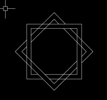
result:- finally i got the result by using auto CAD.
8.
Aim:- To construct the given drawing by using autoCAD sofware.
Procedure :-
1.By using circlr & rad,dia i created circles at middle.
2. i created line by using line command .
3. By using line command and then by using circle radius comand i created the circles with reference to the previous section.
4.By using oject snap option i created the circles at the given distance.
5. by using line i joined external lines by trial and error method.
6. Provided drawing is constructed by auto cad as given below.
7. i gave dimensions & text with suitable dimstyle.
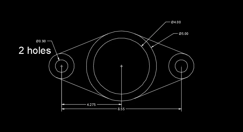
result:- finally i got the result by using auto CAD.
10.
Aim:- To construct the given drawing by using autoCAD sofware.
Procedure :-
1.By using circlr & radius i created circles at ends with respect to given distance.
2. i created arcs at top & bottom by using arc comand .
3. By using trial and error method i completed the drawing as given below.
4.By using oject snap option i created the circles at the given distance.
6. Provided drawing is constructed by auto cad as given below.
7. i gave dimensions & text with suitable dimstyle.
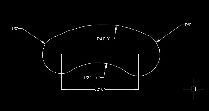
result:- finally i got the result by using auto CAD.