Structural Modelling using Etabs 2018
AIM
To conceptualize a framing plan layout for a G+7 residential building in zone 5 and model the building in Etabs.
INTRODUCTION
ETABS is an engineering software product that caters to multi-story building analysis and design. Modeling tools and templates, code-based load prescriptions, analysis methods and solution techniques, all coordinate with the grid-like geometry unique to this class of structure.
PROCEDURE
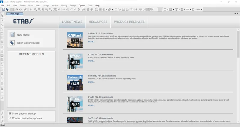
- Open ETABS Software
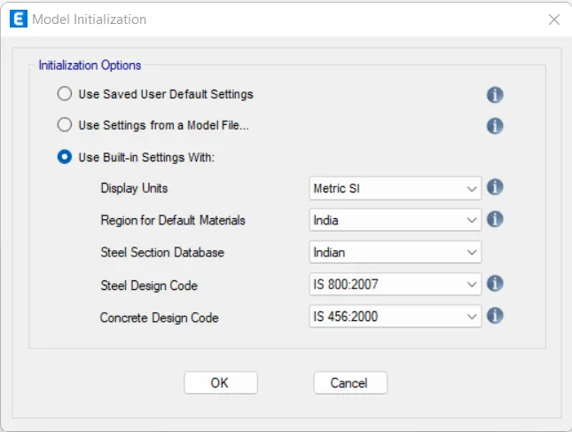
STEP 1: Model Initialization
- Click 'New Model' and select 'Use Built-in Settings With:'
- Assign all options as given below
- Click 'OK'
STEP 2: Grid Spacing
- Click 'Custom Grid Spacing'
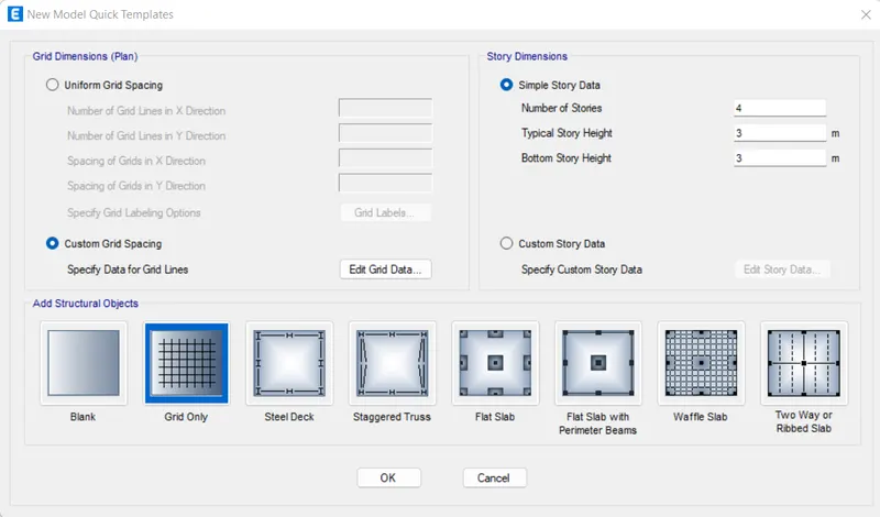
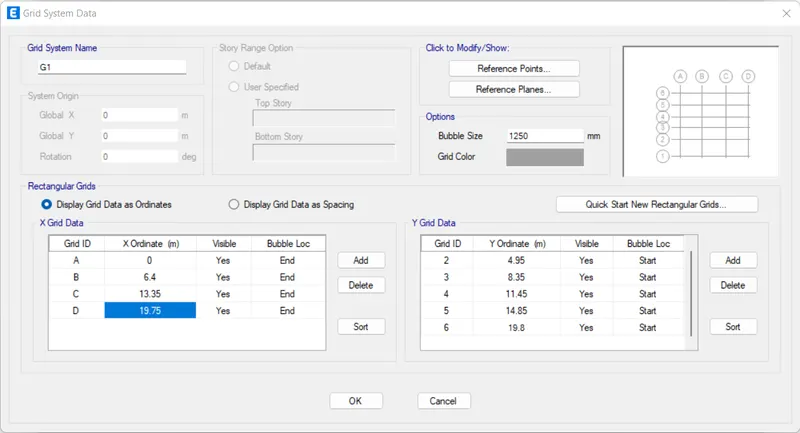
- Click 'Edit Grid Data'
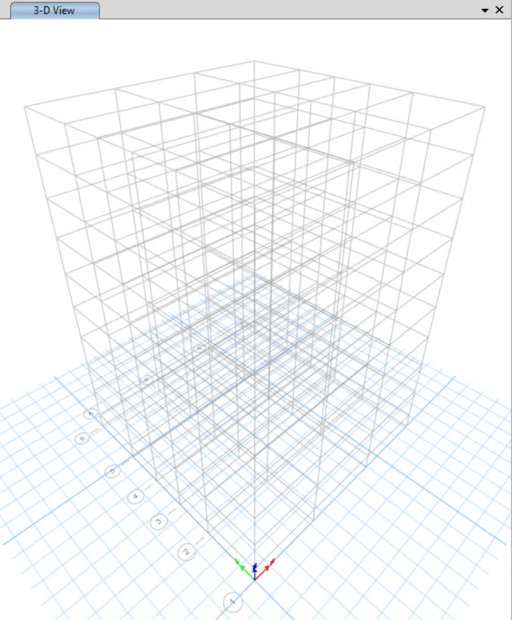
- Assign 'X Ordinate' and 'Y Ordinate' as shown below
- Click 'OK'
STEP 3: Story Data
- Click 'Custom Story Data'
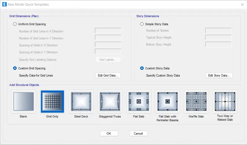
- Click 'Edit Story Data'
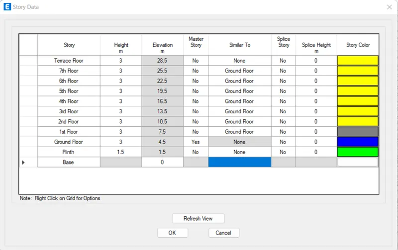
- Assign 'Story' and 'Height' as shown in this figure
- Assign 'Ground Floor' as the 'Master Story'
- Assign '1st Floor' to '7th Floor' as 'Similar To' 'Ground Floor'
- Click 'OK'
- Click 'OK'
STEP 4: Material Properties
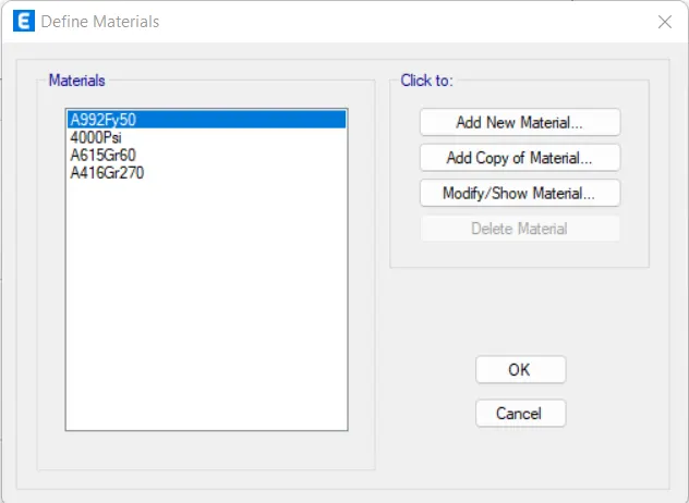
- Click 'Material Properties' under the 'Define' tab

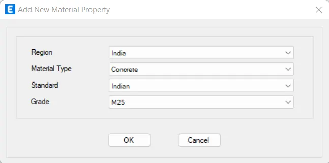
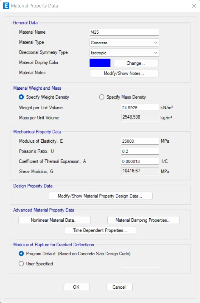
M25
- Click 'Add New Material'
- Assign all options as given below
- Click 'OK'
- Click 'OK'
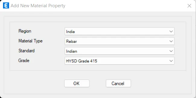
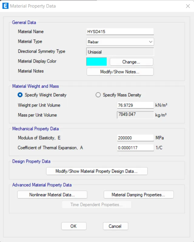
Grade 415
- Again, click 'Add New Material'
- Assign all options as given below
- Click 'OK'
- Click 'OK'
Grade 500
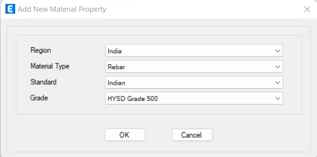
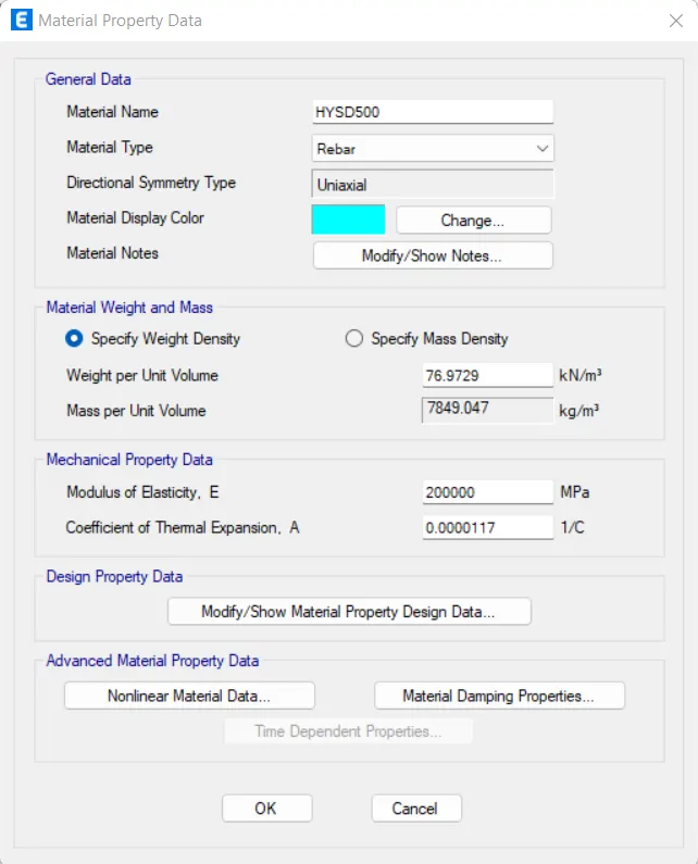
- Again, click 'Add New Material'
- Assign all options as given below
- Click 'OK'
- Click 'OK'
STEP 5: Add Beam Properties
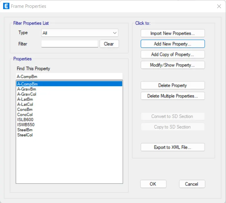
- Click 'Frame Section' in the 'Section Properties' under the 'Define' tab

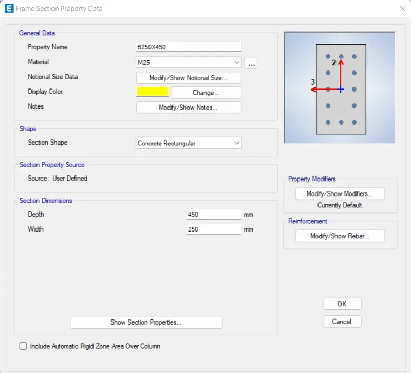
Beam 250X450
- Click 'Add New Property'
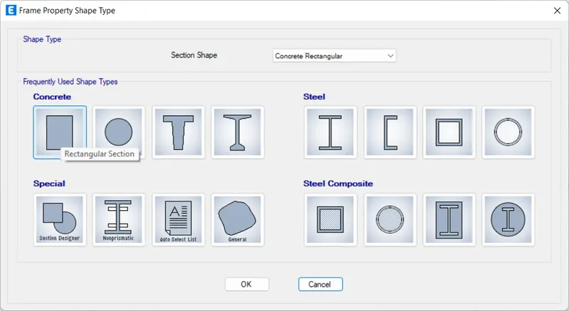
- Click 'Rectangular Section'
- Assign all options as given below
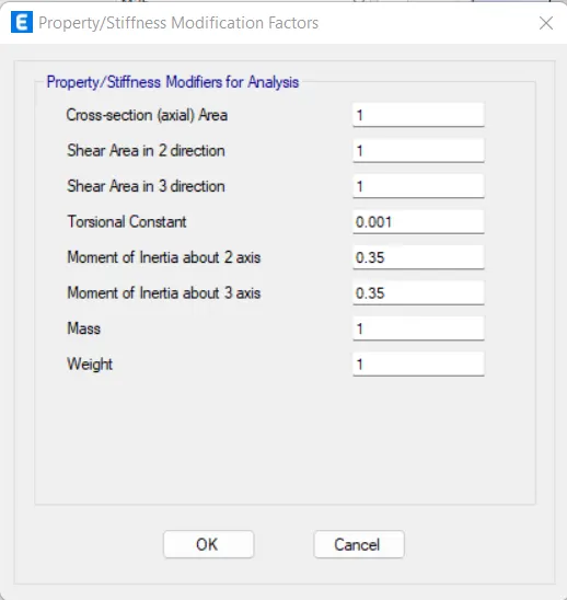
- Click 'Modify/Show Modifiers'
- Assign all options as given below
- Click 'OK'
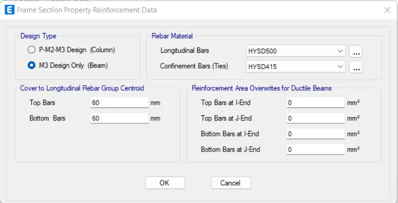
- Click 'Modify/Show Rebar'
- Assign all options as given below
- Click 'OK'
- Click 'OK'
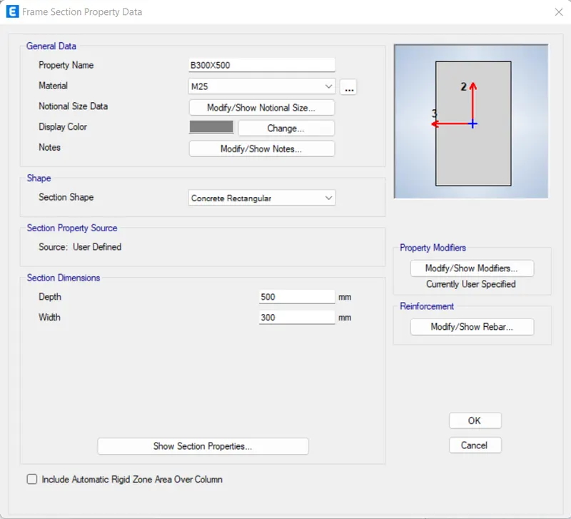
Beam 300X500
- Click 'Add New Property'
- Click 'Rectangular Section'
- Assign all options as given below
- Click 'Modify/Show Modifiers'
- Assign all options as given below
- Click 'OK'
- Click 'Modify/Show Rebar'
- Assign all options as given below
- Click 'OK'
- Click 'OK'
STEP 6: Add Column Properties
- Click 'Frame Section' in the 'Section Properties' under the 'Define' tab
Column 400X600
- Click 'Add New Property'
- Click 'Rectangular Section'
- Assign all options as given below
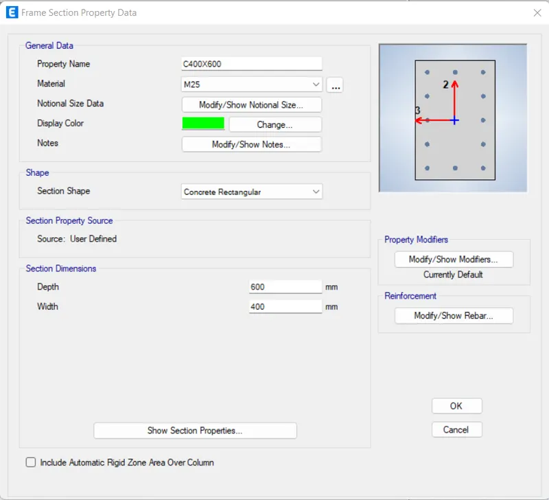
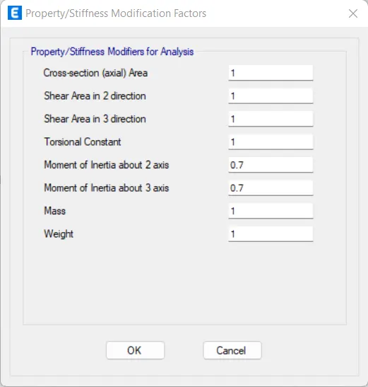
- Click 'Modify/Show Modifiers'
- Assign all options as given below
- Click 'OK'
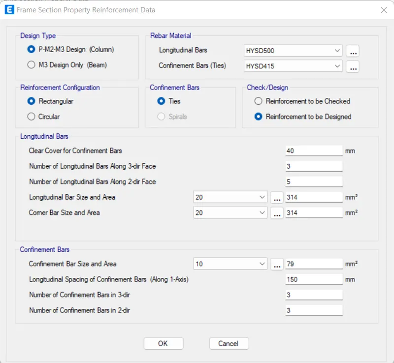
- Click 'Modify/Show Rebar'
- Assign all options as given below
- Click 'OK'
- Click 'OK'
Column 600X900
- Click 'Add New Property'
- Click 'Rectangular Section'
- Assign all options as given below
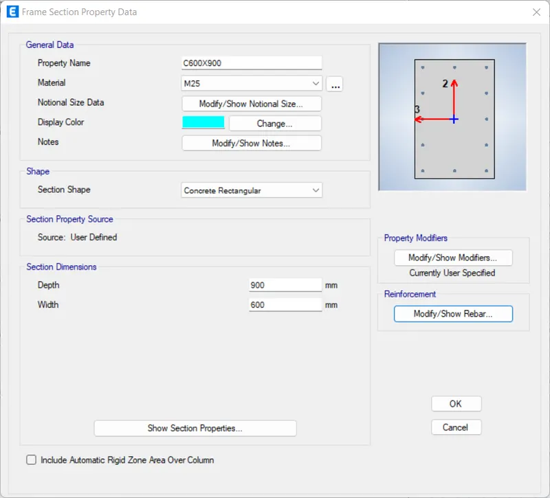
- Click 'Modify/Show Modifiers'
- Assign all options as given below
- Click 'OK'
- Click 'Modify/Show Rebar'
- Assign all options as given below
- Click 'OK'
- Click 'OK'
STEP 7: Add Slab Properties
- Click 'Slab Section' in the 'Section Properties' under the 'Define' tab
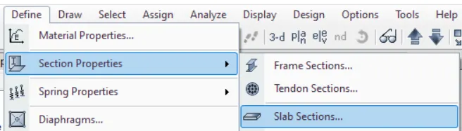
Slab 115mm
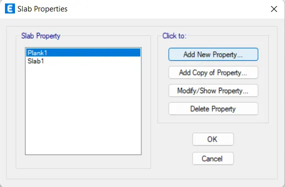
- Click 'Add New Property'
- Assign all options as given below
- Click 'OK'
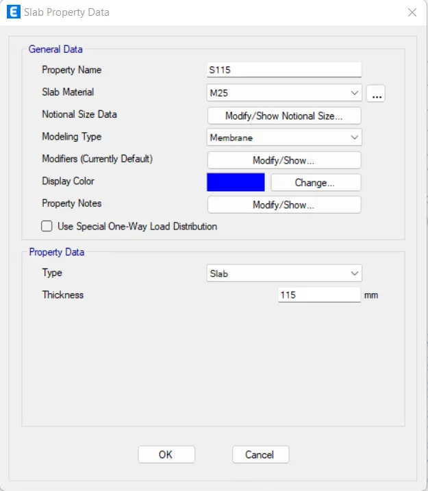
- Click 'OK'
Stair Slab 200mm
- Click 'Add New Property'
- Assign all options as given below
- Click 'OK'
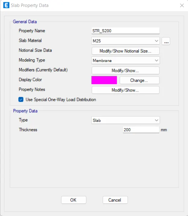
- Click 'OK'
STEP 8: Add Slab Properties
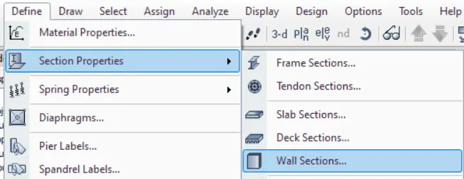
- Click 'Wall Sections' in the 'Section Properties' under the 'Define' tab
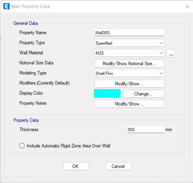
Shear Wall 300mm
- Click 'Add New Property'
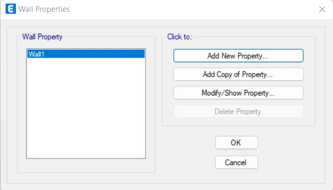
- Assign all options as given below
- Click 'OK'
- Click 'OK'
STEP 8: Add Columns, Beams, Shear Walls and Slabs
Columns
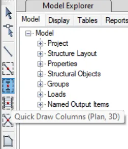
- Click 'Quick Draw Columns' from the toolbars
- Select 'All Stories'
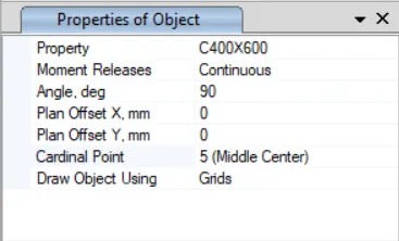
- Assign all options as given below
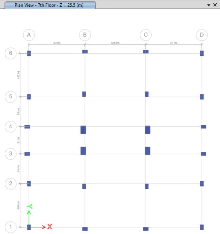
- Place the columns on grids
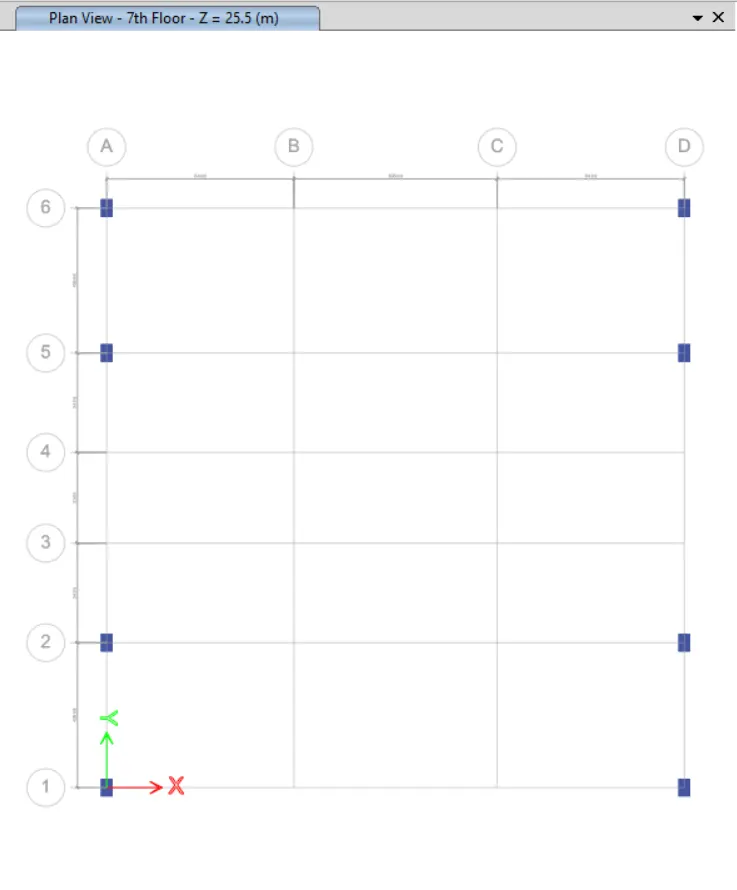
- Adjust the 'Properties of Objects' and place the columns accordingly
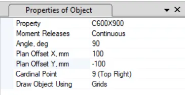
- Assign all options as given below
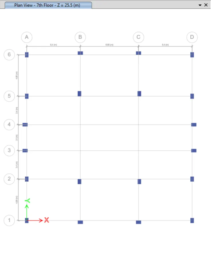
- Place the columns on grids
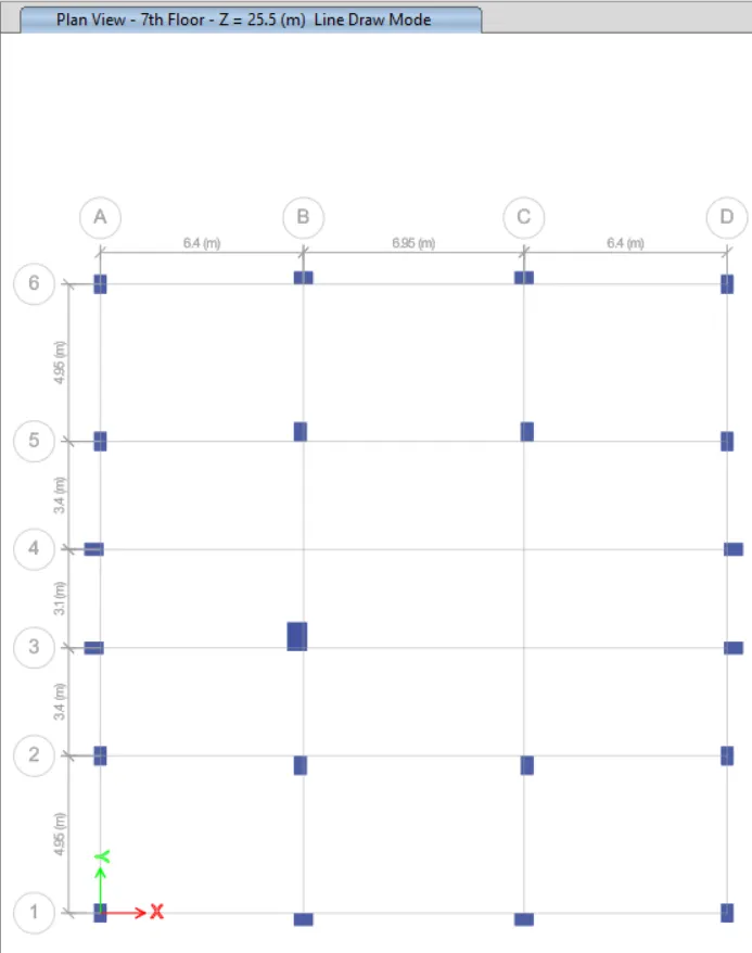
- Adjust the 'Properties of Objects' and place the columns accordingly
Beams
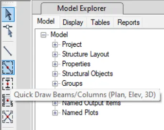
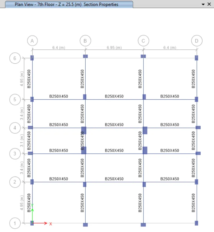
- Click 'Quick Draw Beams' from the toolbars
- Assign all options as given below
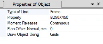
- Place the beams on lines
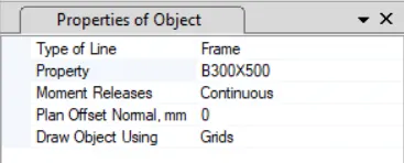
- Assign all options as given below
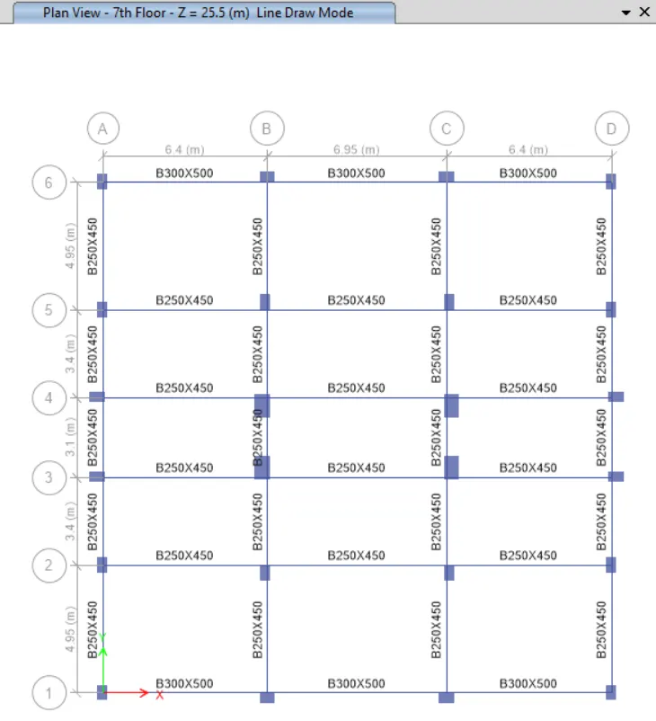
- Place the beams on lines
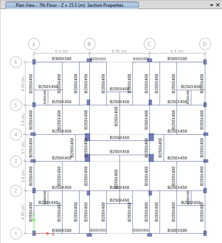
- Using edit options draw secondary beams as shown below
Shear Walls
- Click 'Draw Walls' from the toolbars
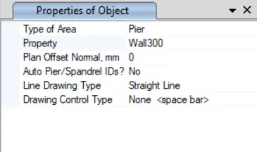
- Assign all options as given below
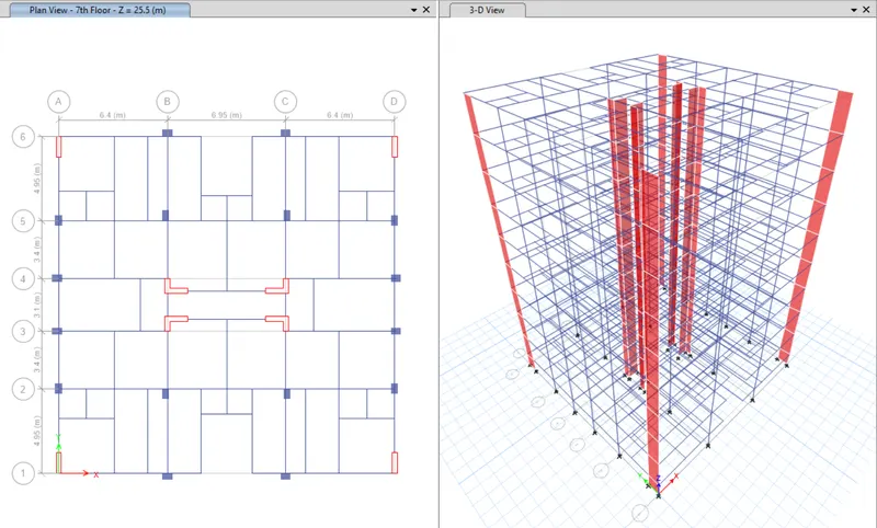
- Place the walls accordingly
Slabs
- Click 'Quick Draw Floor/Wall' from the toolbars
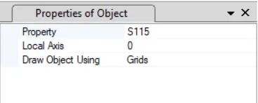
- Assign 'S115' as the property
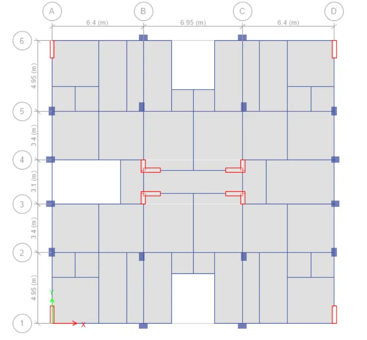
- Click inside the desired grids
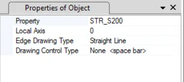
- Assign 'STR_S200' as the property
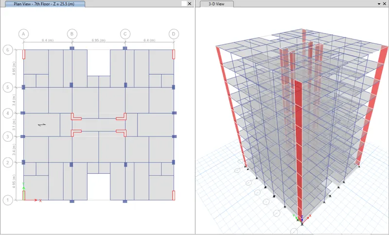
- Click inside the desired grids
STEP 9: Provide Fixed Joint at Base
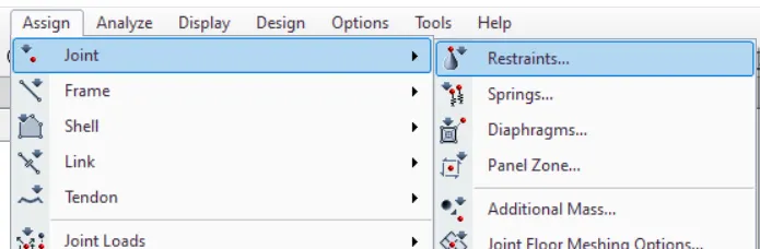
- Go to 'Base' plan view
- Select all joints
- Click 'Restraints' in the 'Joint' underthe 'Assign' tab
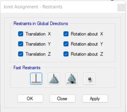
- Select 'Fixed' and click 'OK'
STEP 10: Add Load Patterns
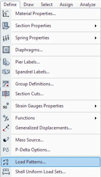
- Click 'Load Patterns' under the 'Define' tab
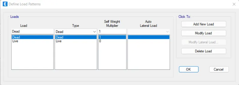
- Apply all loads
- After defining a load, click 'Add New Load'
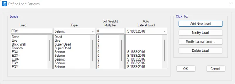
- Click 'Modify Lateral Load' for load 'EQX', 'EQX+', 'EQX-', 'EQY', 'EQY+' and 'EQY-'
- Settings for EQX
- Assign all options as given below
- Click 'OK'
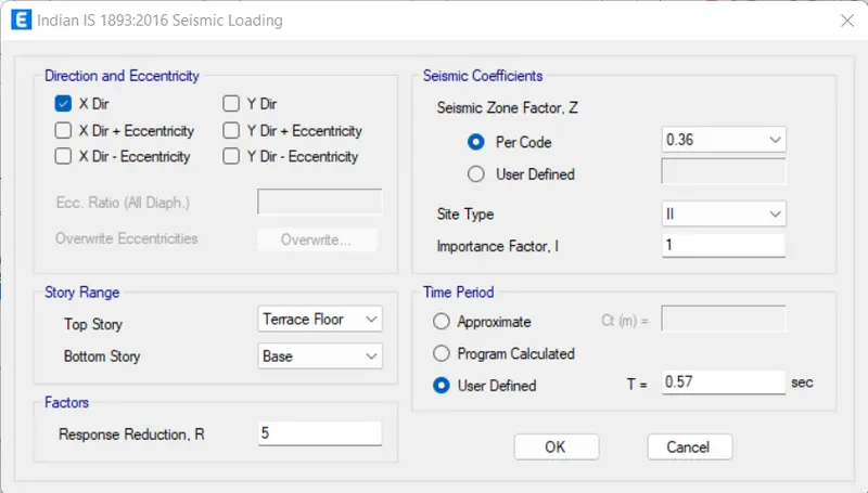
- Settings for EQX+
- Assign all options as given below
- Click 'OK'
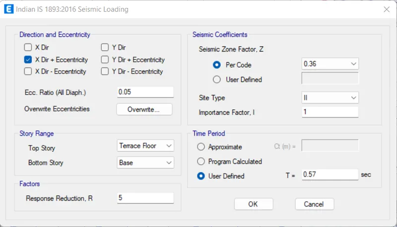
- Settings for EQX-
- Assign all options as given below
- Click 'OK'
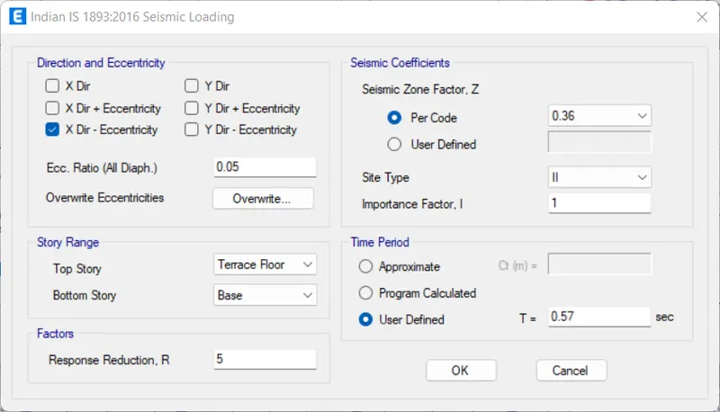
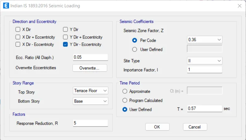
- Settings for EQY
- Assign all options as given below
- Click 'OK'
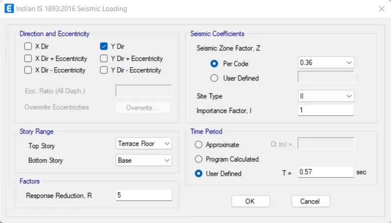
- Settings for EQY+
- Assign all options as given below
- Click 'OK'
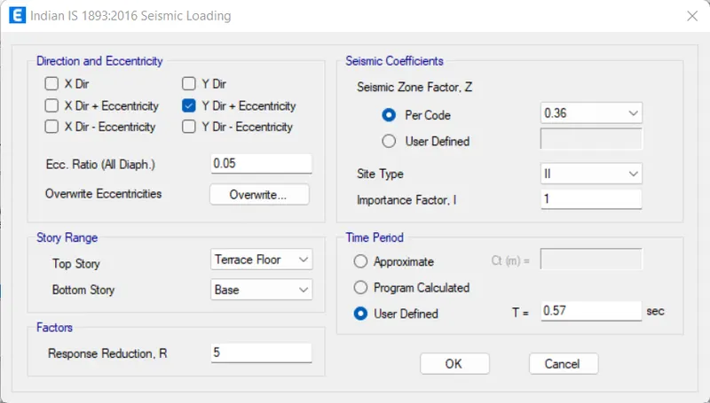
- Settings for EQY-
- Assign all options as given below
- Click 'OK'
- Click 'OK'
STEP 11: Add Mass Source Data
- Click 'Mass Source' under the 'Define' tab
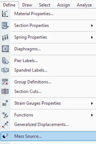
- Click 'Modify/Show Mass Source'
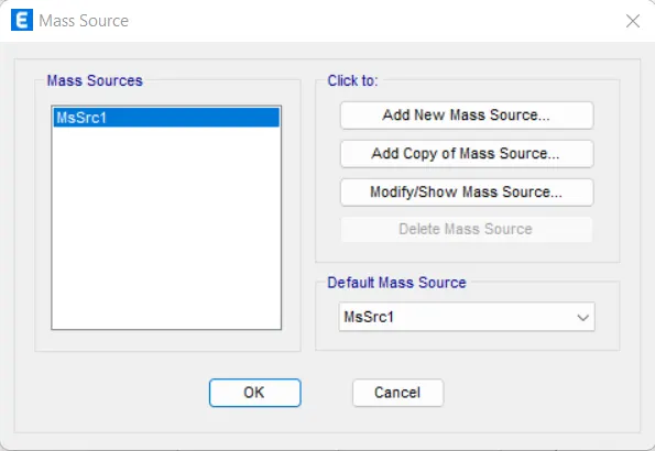
- Assign all options as given below
- Click 'OK'
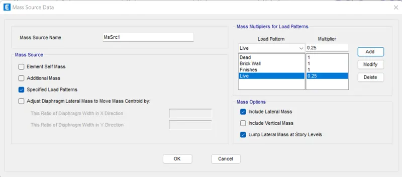
- Click 'OK'
STEP 12: Assign Loads
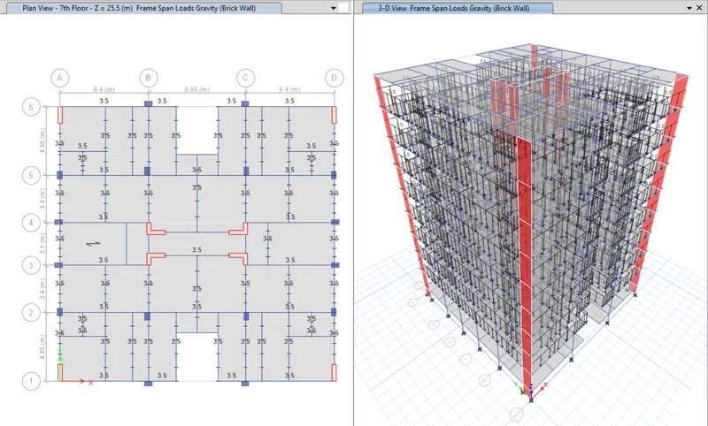
Brickwall Load
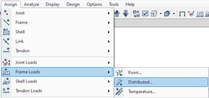
- Select beams which undergo brick load
- Click 'Distributed' in the 'Frame Loads' under the 'Assign' tab
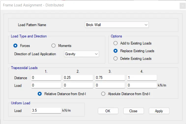
- Assign 'Brick Wall' load as 3.5 KN/m as shown below
- Click 'Apply'
Live Load
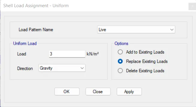
- Select slabs which undergo 3 KN/m2
- Click 'Uniform' in the 'Shell Loads' under the 'Assign' tab
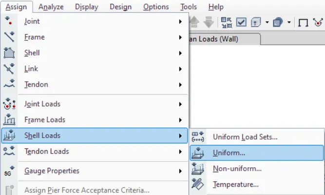
- Assign 'Live' load as 3KN/m2 as shown below
- Click 'Apply'
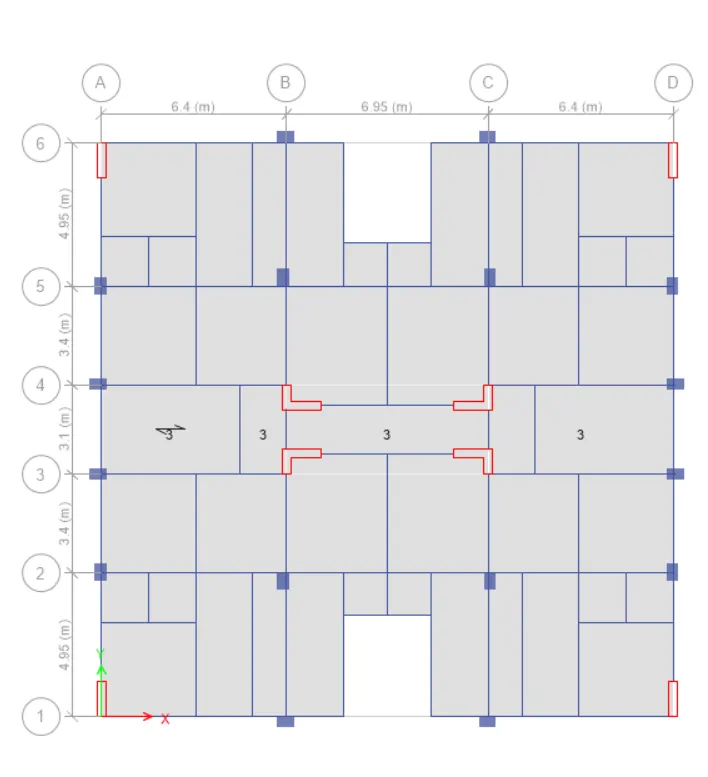
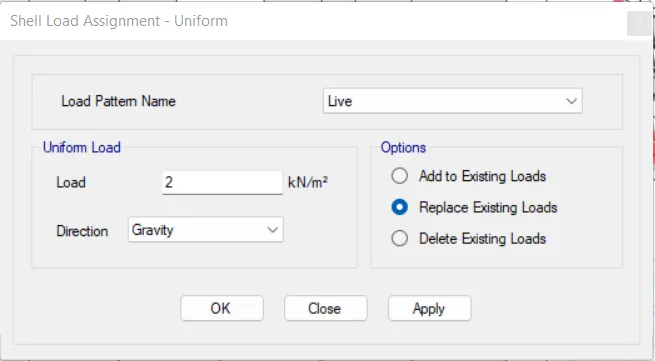
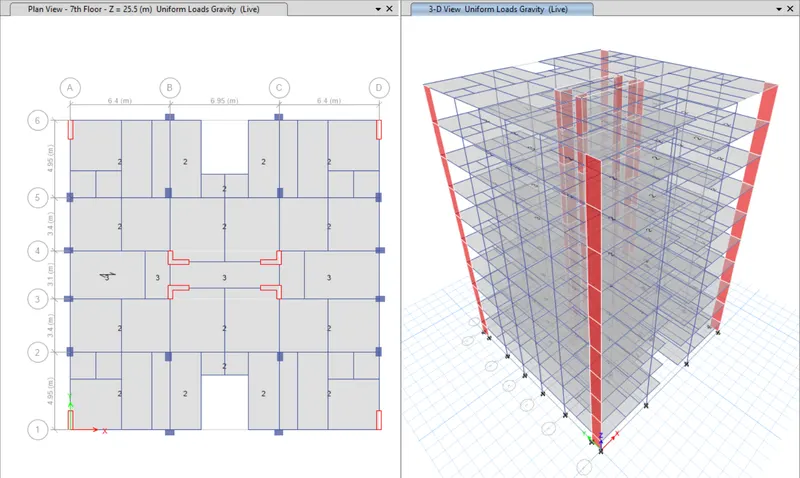
- Select slabs which undergo 2 KN/m2
- Click 'Uniform' in the 'Shell Loads' under the 'Assign' tab
- Assign 'Live' load as 2KN/m2 as shown below
- Click 'Apply'
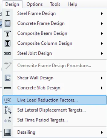
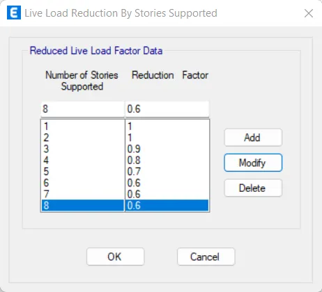
- Click 'Live Load Reduction Factors' underthe 'Design' tab
- Select 'User Defined' and click 'Define'
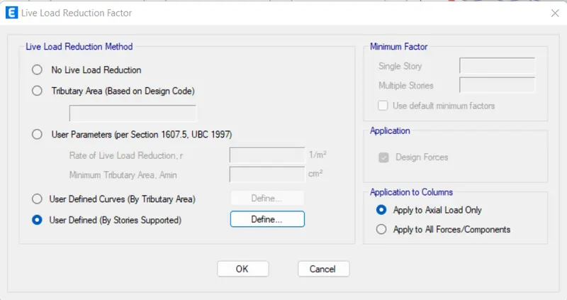
- Assign all values as shown below
- Click 'OK'
- Click 'OK'
Floor Finish
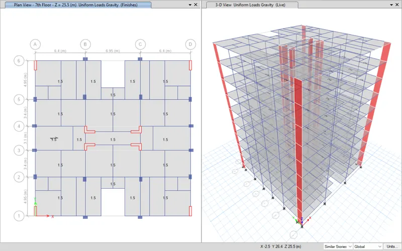
- Select all the slabs
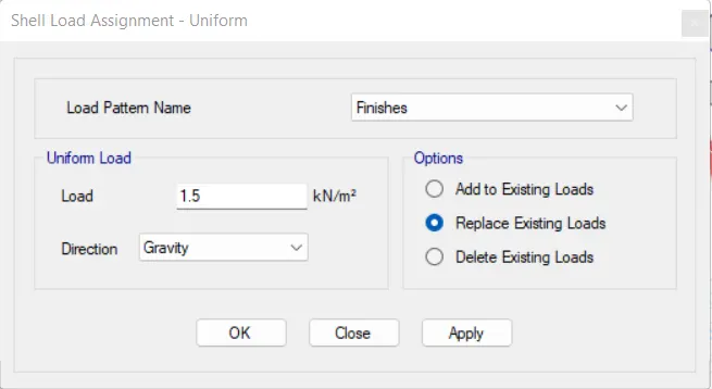
- Click 'Uniform' in the 'Shell Loads' under the 'Assign' tab
- Assign 'Finishes' load as 1.5KN/m2 as shown below
- Click 'Apply'
Diaphragms
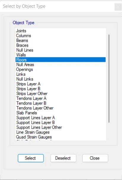
- Click 'Object Type' under the 'Select' tab
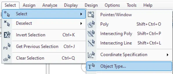
- Click 'Floors' and press 'Select'
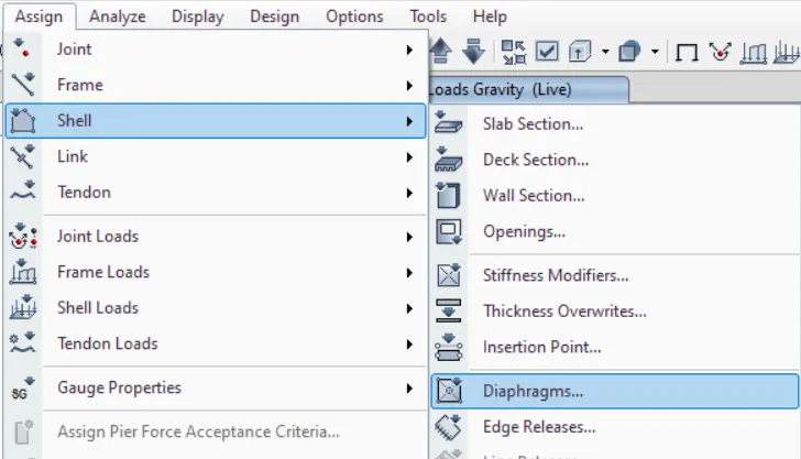
- Click 'Diaphragms' in the 'Shell' under the 'Assign' tab
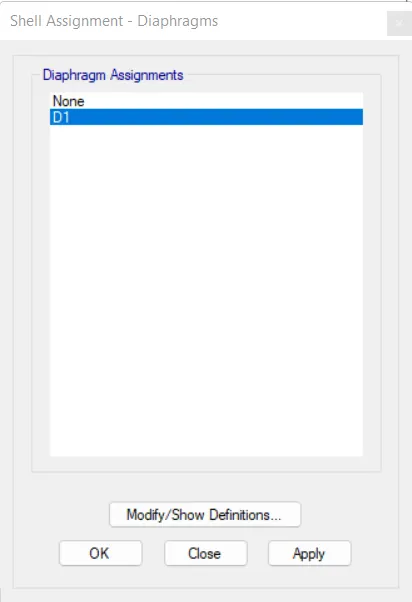
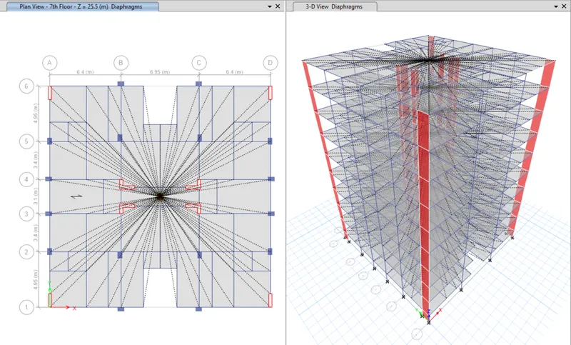
- Select 'D1' and click 'Apply'
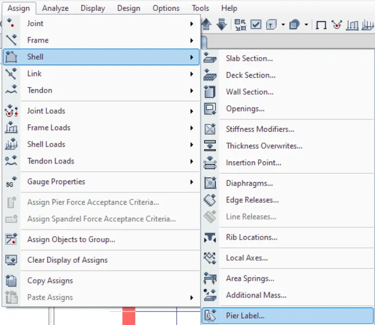
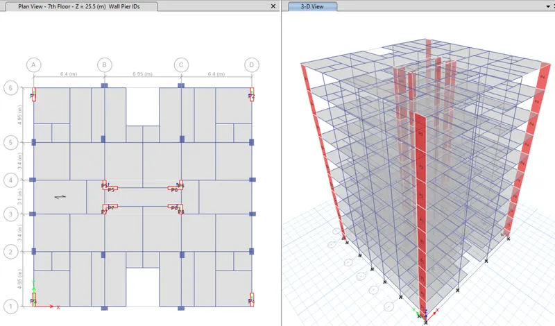
Pier Label
- Select each shear wall assign individual pier label to each wall
- Click 'Pier Label' in the 'Shell' under the 'Assign' tab
STEP 13: Modal Cases
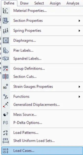
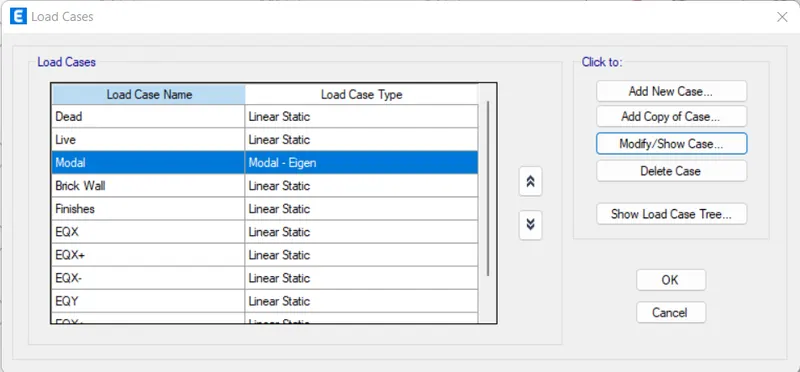
- Click 'Load Cases' under the 'Define' tab
- Click 'Modify/Show Case'
- Assign all values as shown below
- Click 'OK'
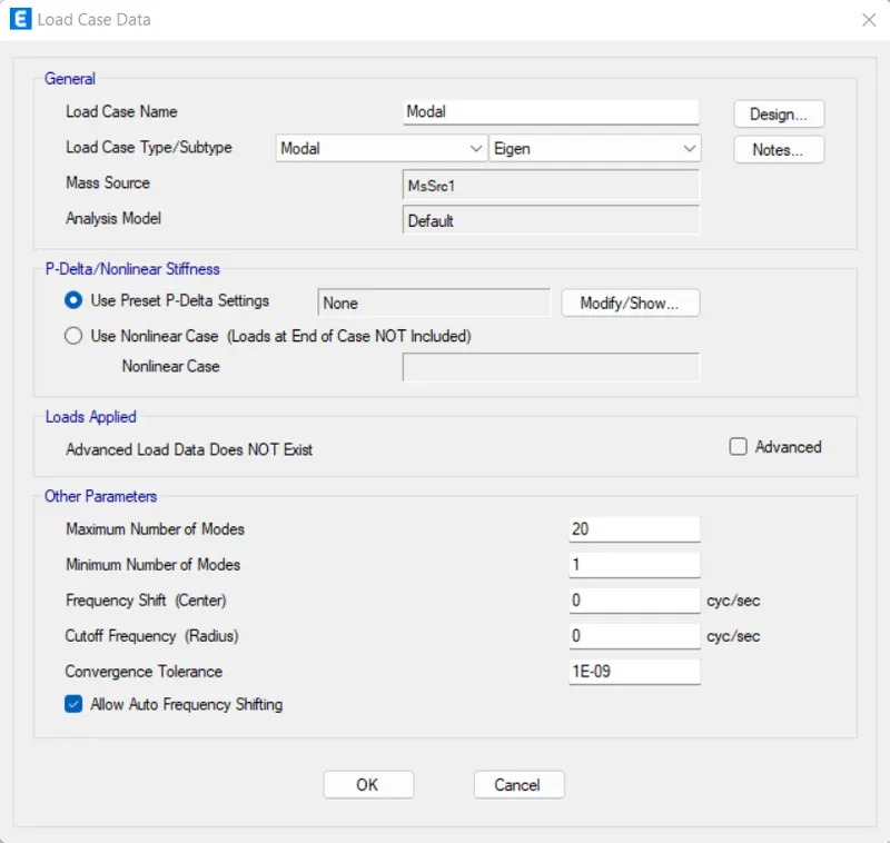
- Click 'OK'
STEP 14: Response Spectrum
- Click 'Response Spectrum' in the 'Functions' under the 'Define' tab
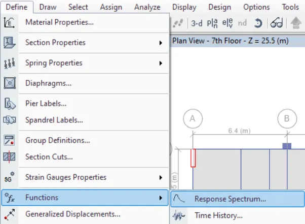
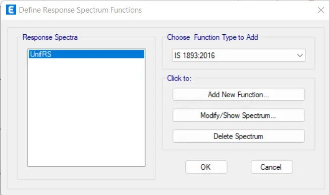
- Select 'IS 1893:2016' and click 'Add New Function'
- Assign all values as shown below
- Click 'OK'
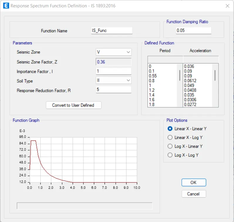
- Click 'OK'
- Click 'Load Cases' under the 'Define' tab
- Click 'Add New Case'
- Assign all values as shown below
- Click 'OK'
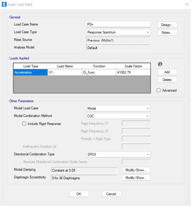
- Again, click 'Add New Case'
- Assign all values as shown below
- Click 'OK'
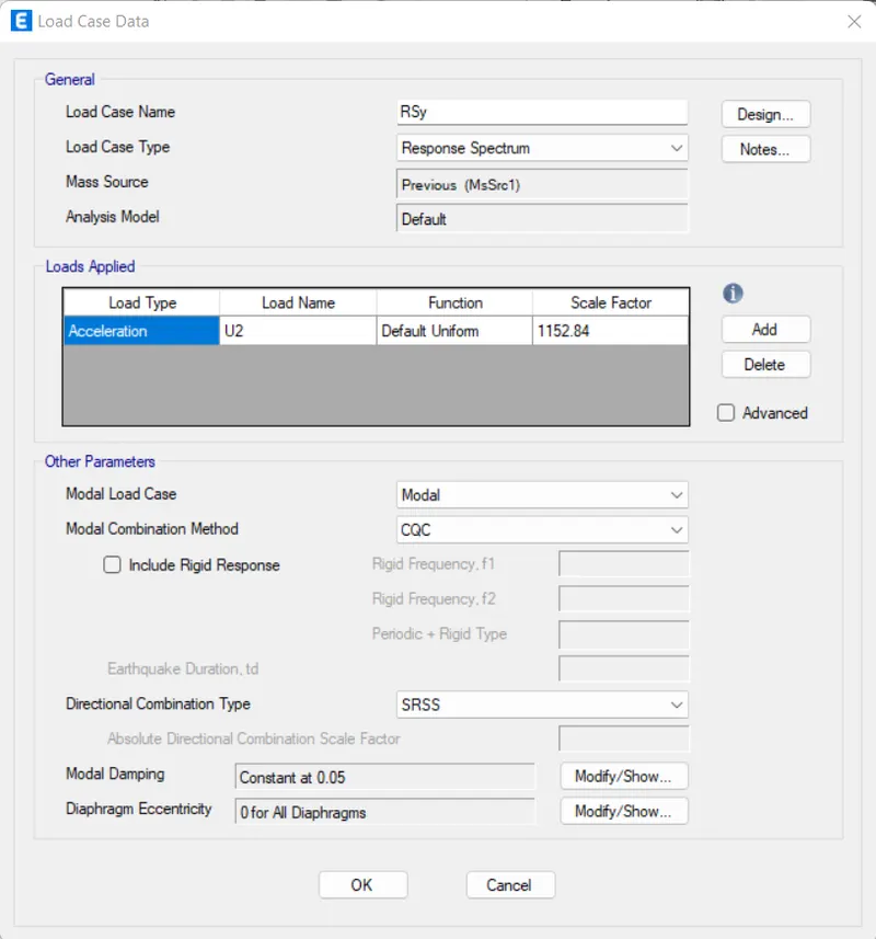
- Click 'OK'
STEP 15: Load Combinations
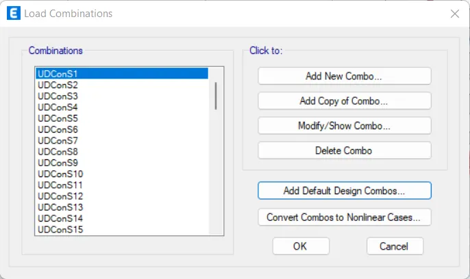
- Click 'Load Combinations' under the 'Define' tab
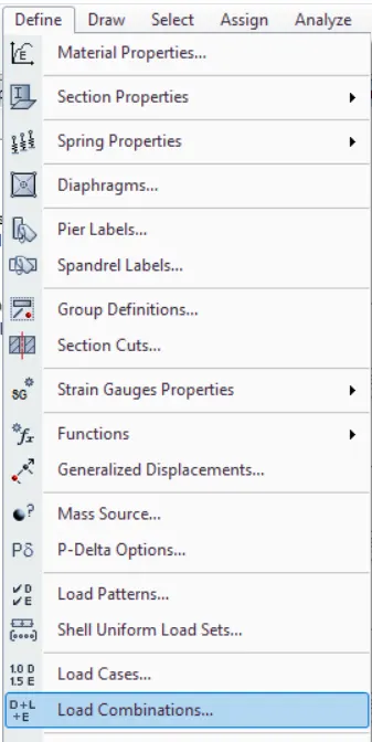
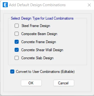
- Click 'Add Default Design Combos'
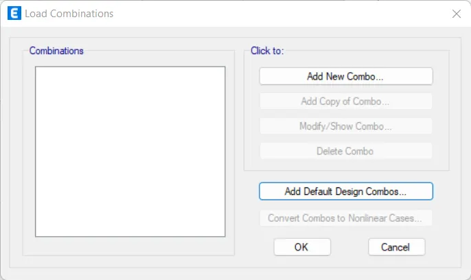
- Select 'Concrete Frame Design', 'Concrete Shear Wall Design' and 'Convert to User Combinations'
- Click 'OK'
- Click 'OK'
STEP 16: Run Analysis
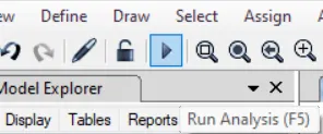
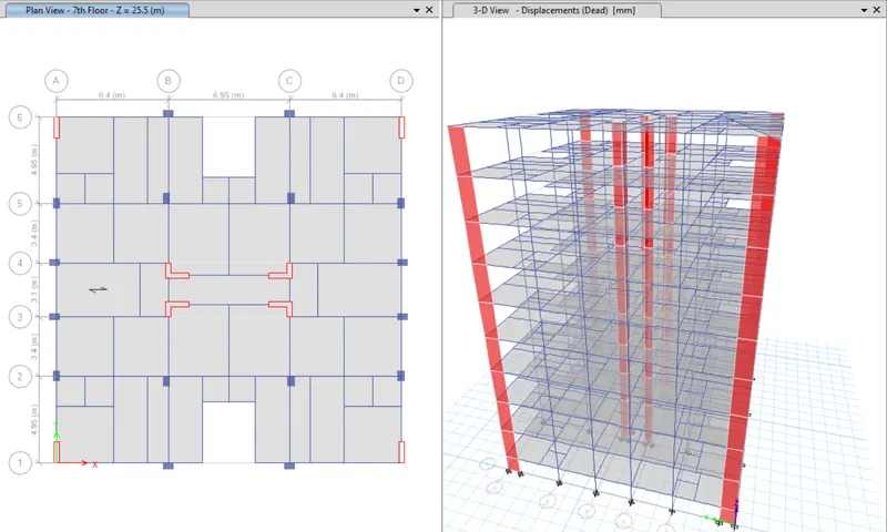
- Click 'Run Analysis' from top menu
STEP 17: Model Tables
- From 'Model Explorer', select
- ANALYSIS RESULTS > Structure Output > Base Reactions > Table: Base Reactions

- Right click and then click 'Show Table'
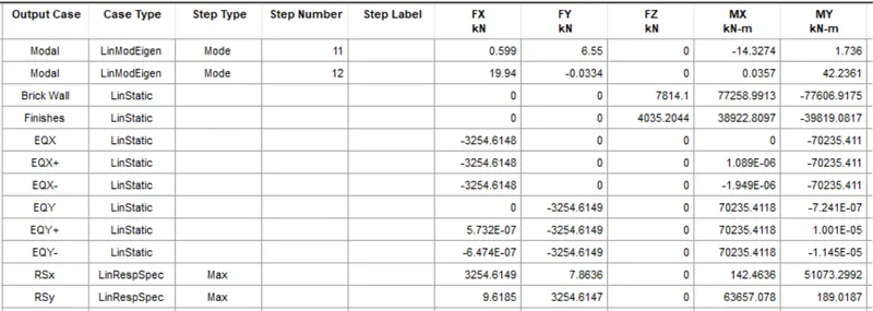
EQX and EQY values equal to RSx and RSy values
- From 'Model Explorer', select
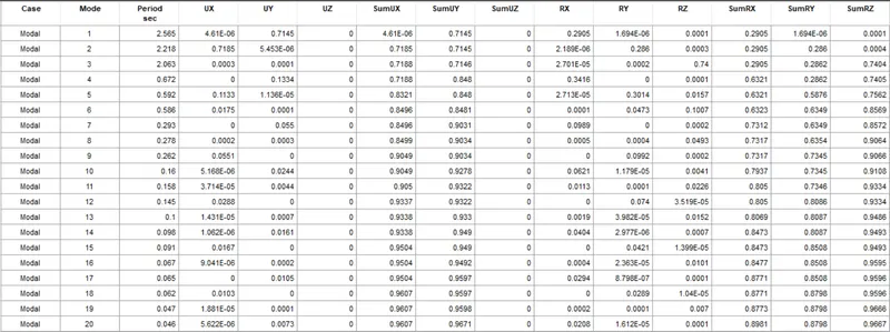
- ANALYSIS RESULTS > Structure Output > Modal Information > Table: Modal Participating Mass Ratio
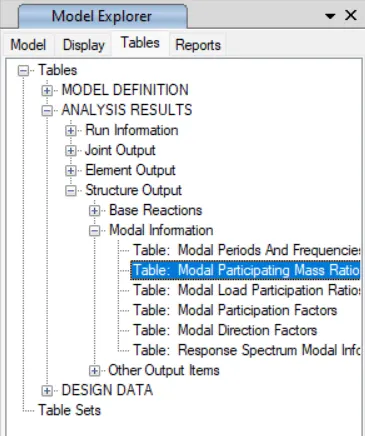
- Right click and then click 'Show Table'
- From 'Model Explorer', select
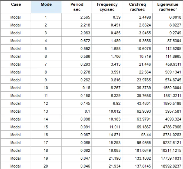
- ANALYSIS RESULTS > Structure Output > Modal Information > Table: Modal Periods And Frequencies
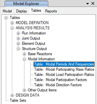
- Right click and then click 'Show Table'
STEP 18: Story Response Plots
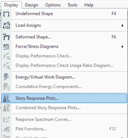
- Click 'Story Response Plots' under the 'Display' tab
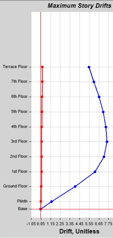
- Assign 'Display Type' as 'Max story drifts' and 'Case/Combo' as 'EQX'
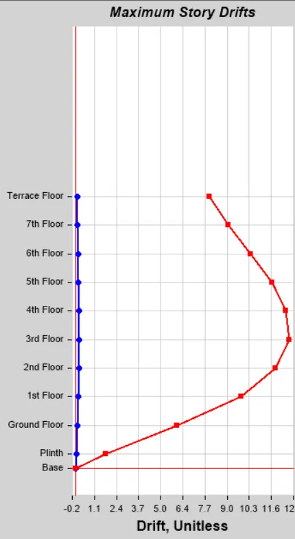
- Assign 'Display Type' as 'Max story drifts' and 'Case/Combo' as 'EQY'
RESULTS
A G+7 residential building in zone 5 is conceptualized and modelled on ETABS. The tables and graphs needed to obtain result for the checks are given in the procedure. The final result is shown in the table below.
| Checks | Results |
| Modal mass participation for first 3 modes dominates at least 65% | Achieved |
| Mode-1 and Mode-2 differs by 10% | Achieved |
| Principal modes be greater than Torsional mode | Achieved |
| Inter story drift ratio limited to 0.004 | Not Achieved |
| Axial stress in Column and Shear wall | Achieved |
| Base shear share between shear wall & Columns | Not dual System |