Structural Modelling using Etabs 2018
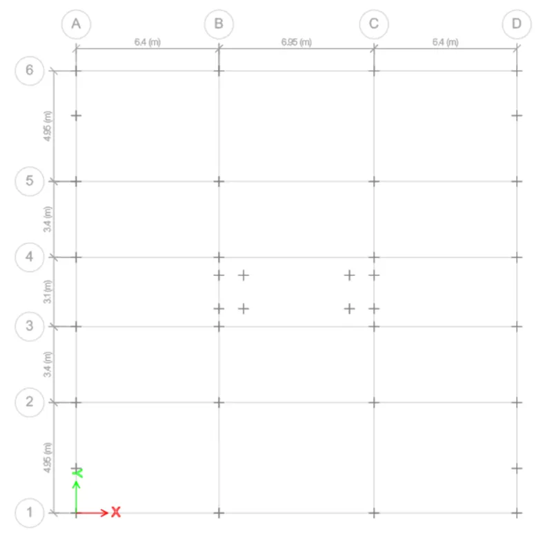
The architectural drawings for a G+7 residential building in zone 5 has been provided. The floor plan is the same for all 7 floor levels. Possible column positions have also been provided. Conceptualize a framing plan layout and then model the building in Etabs. The following architectural drawings have been provided:
- Typical floor plan – The location and thickness of the brick walls and the use of the
space (for estimating live load) can be obtained from this plan - A building section through the staircase and lift core is provided
- Parking layout in the ground floor – the column/shear wall arrangement must not
obstruct entry/exit of vehicles.
The following loadings are to be taken into account: - Brickwall made of AAC blocks
- Finishes – floor tiles of 75 mm thickness
- Live loads as per IS 875 part 2
- AIM Water tank of 20 KL above the staircase at Mumty level
- Lift Machine room at mumty level above lift core
The structural model must comply with provisions of IS 1893 and IS 13920.
Run a modal response spectrum analysis and check analysis results of the etabs model for inter-storey drift requirements, vertical & planar irregularities, minimum shear wall requirements,maximum axial load ratio for column and shear walls, effective moment of inertia for beams
and columns etc.
Please note that the column positions shown in the architectural typical floor plan are only to provide an initial starting point for modelling. Participants will have to change its size, introduce shear walls, and add new vertical elements after running the analysis. You will have to run the analysis multiple times until a structural model is obtained that meets structural code requirements without compromising architectural functions. Also, there is no one ‘correct’ structural system for this challenge. There can be multiple possible solutions for this problem.
ANS :
AIM : To create a model of G+1 building given in the architectural drawing as per the provisions of IS 1983-2016 and IS 13920 followed by response spectrum analysis
PROCEDURE :
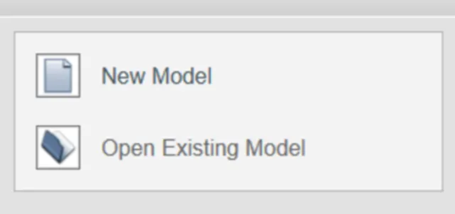
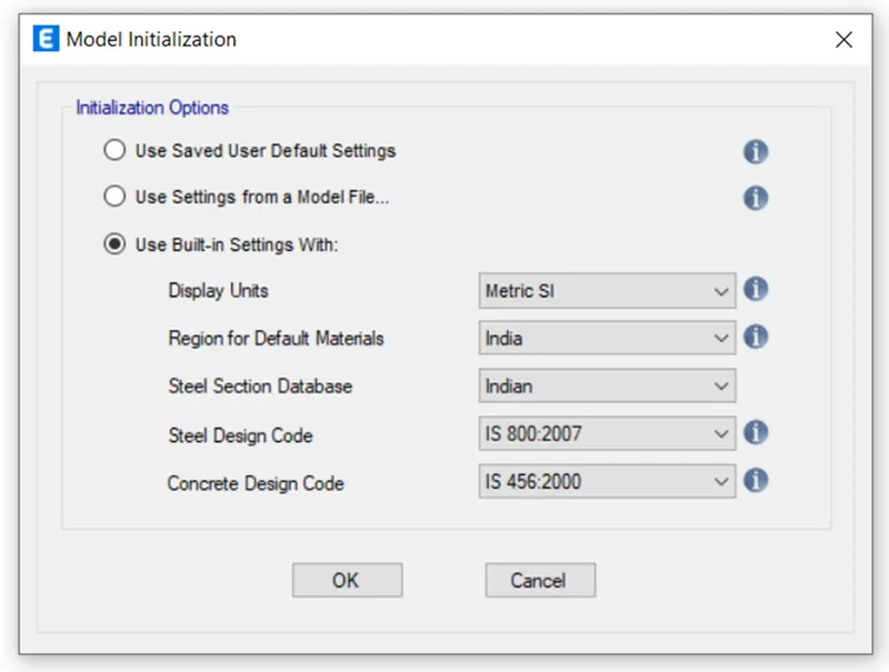
Step 1 : Open then Etabs software and click on new model, the model initialization dialogue box will appear in that select use Built-in settings with and make the settings accordingly and press ok
Step 2 : New model quick template dialogue box will appear
In the dialogue box select custom grid spacing in grid dimension and select custom story data in story dimension
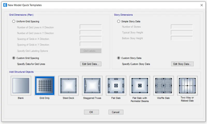
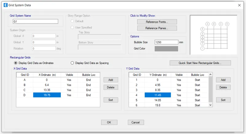
In custom grid spacing click on edit grid data you will get the grid system data dialogue box
Give the data according to the question given in both x and y direction
As per the question the spacing between the grids is 4m in both x and y direction and give other data accordingly and press ok
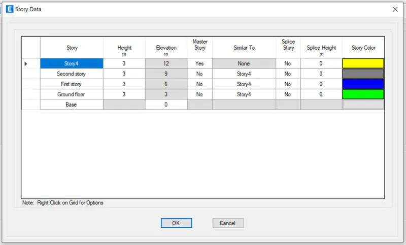
In custom story data click on edit story data you will get the story data dialogue box
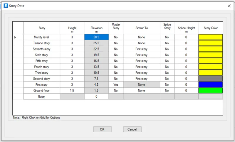
Add the story as per the given question with each story height as 3m and base to plinth floor level as 1.5m as per the given question
Give the master story as first story and for other story give similar to as first story
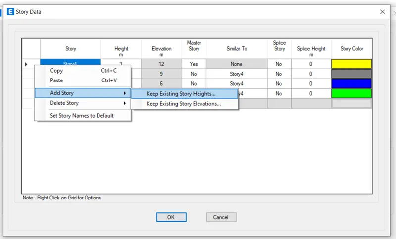
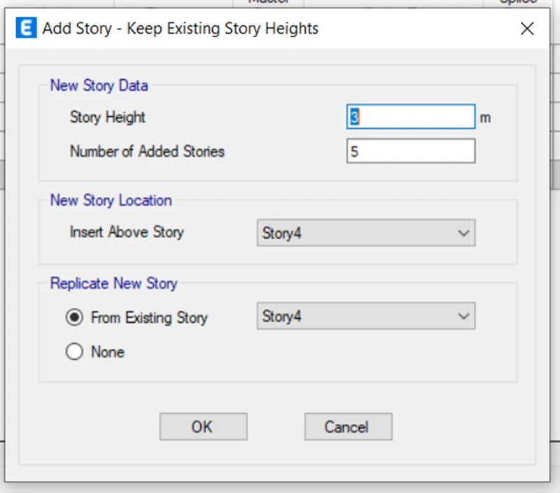
By right clicking the arrow given in top row add the required amount of story and do the settings accordingly and press ok
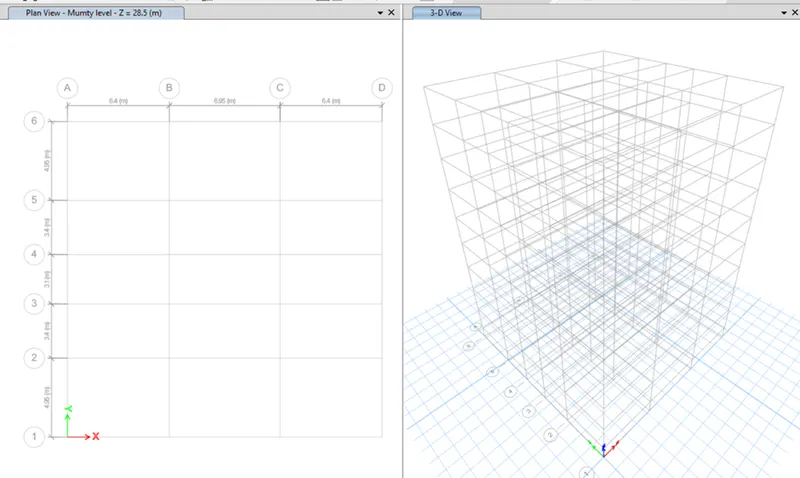
Step 3 : Go to define tab and select material properties
Add grade of concrete as M25 and Grade of steel reinforcement bars as Fe415, Grade of steel reinforcement bars as Fe500 and do the settings accordingly for each material
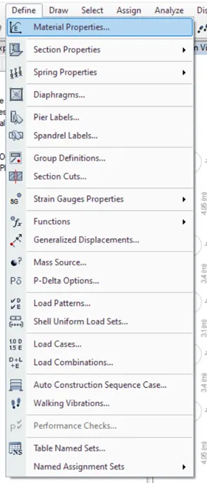
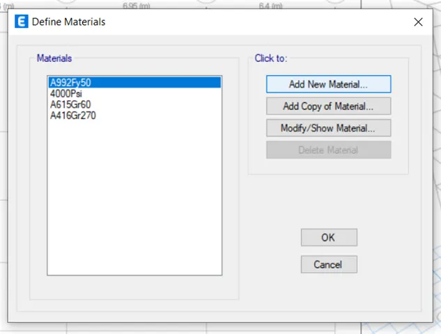
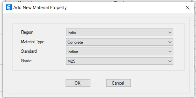
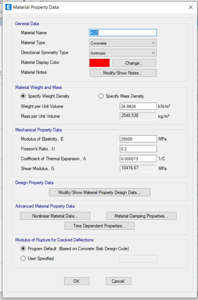
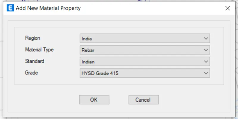
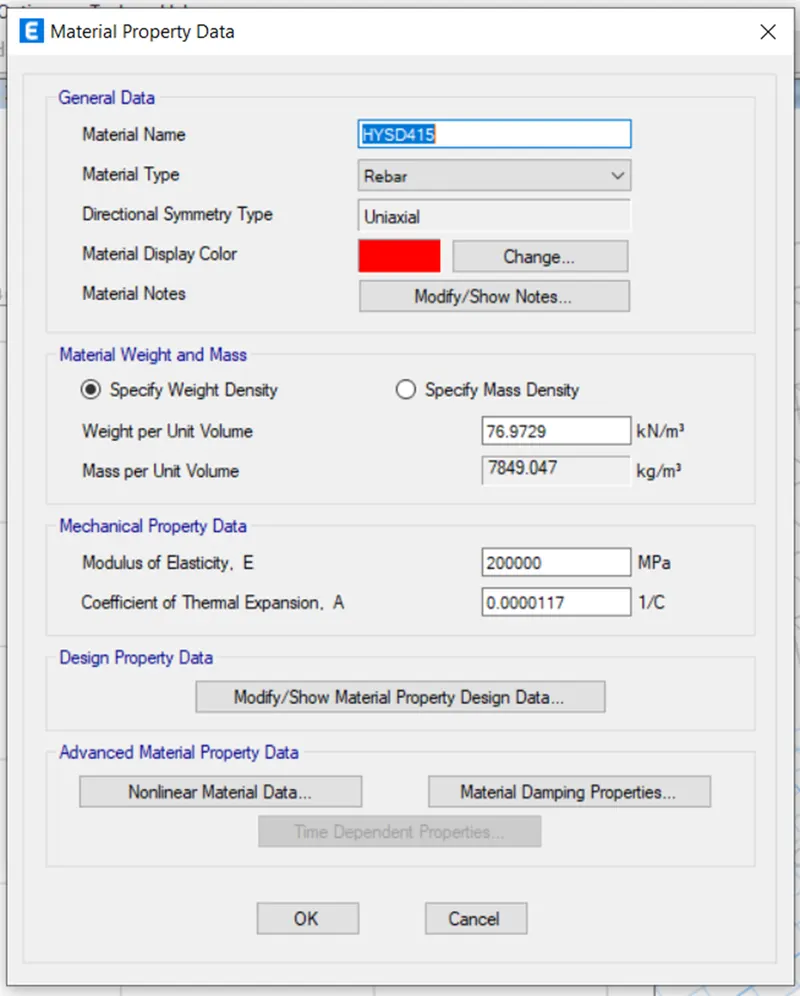
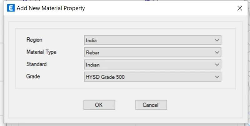
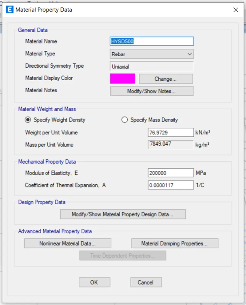
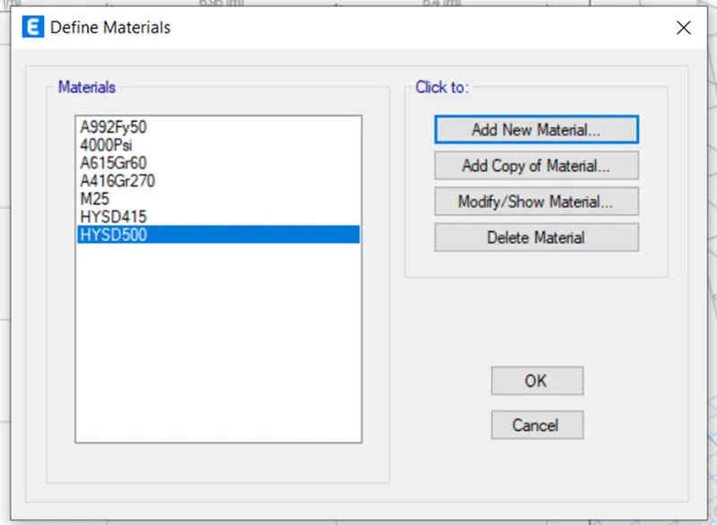
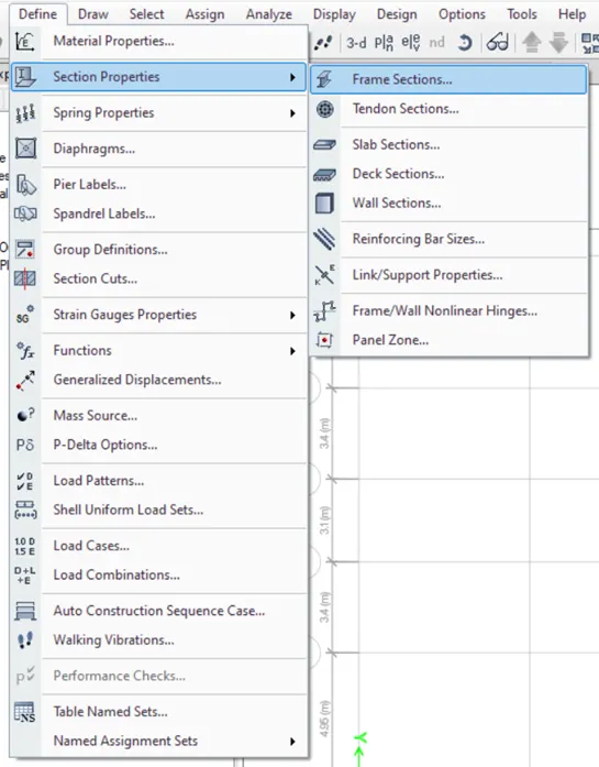
Step 4 : Go to define tab and select section properties in that select frame sections
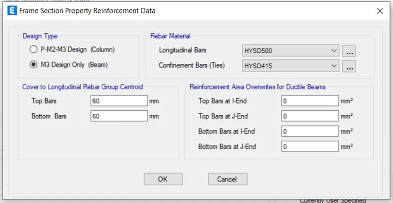
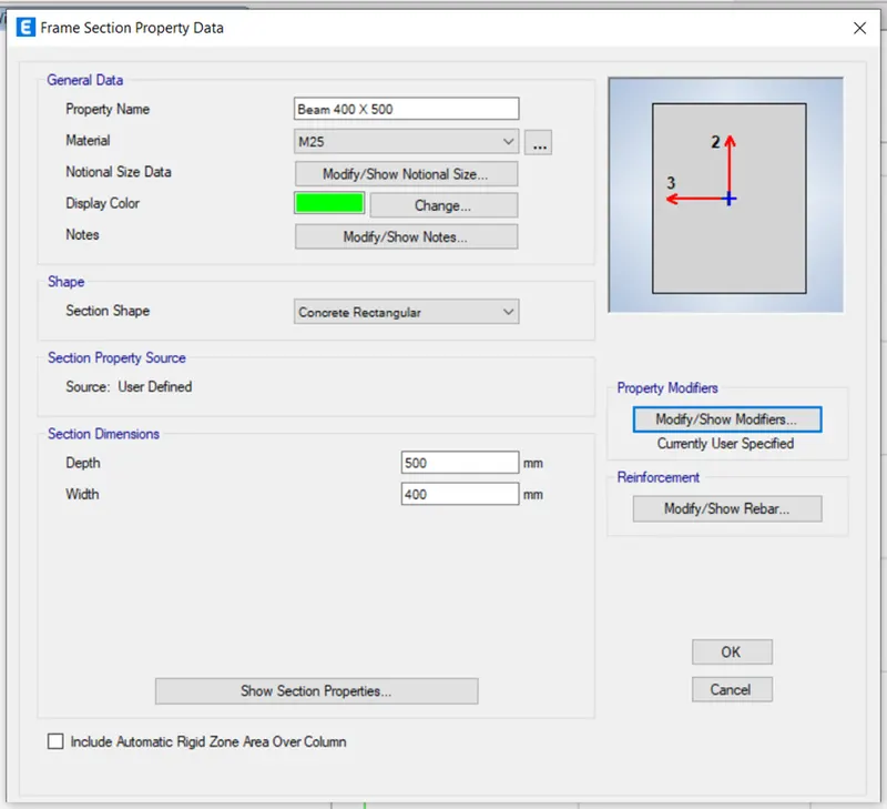
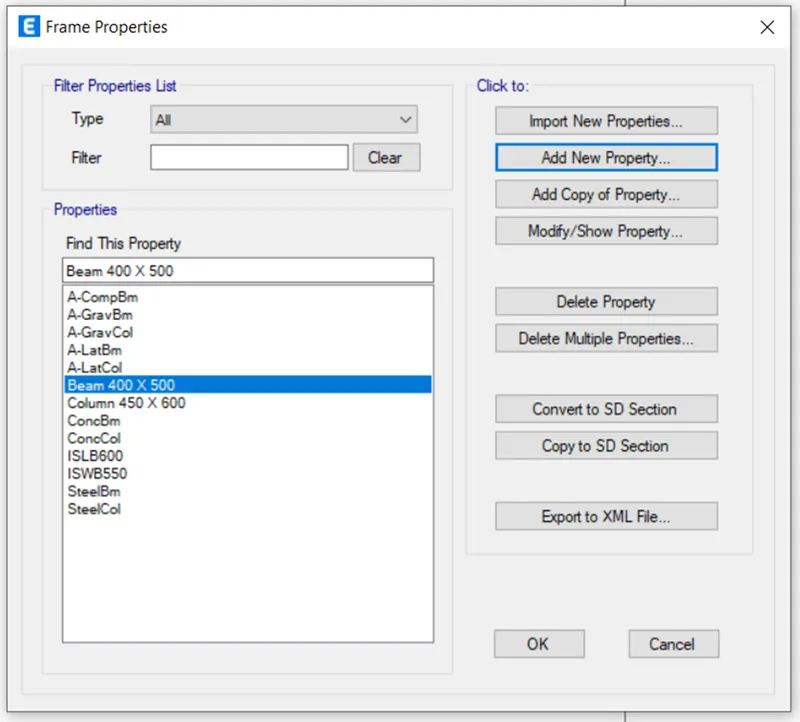
Add column of size 450 x 600 mm and beam of size 400 x 500 mm properties as per the question by clicking on Add new property

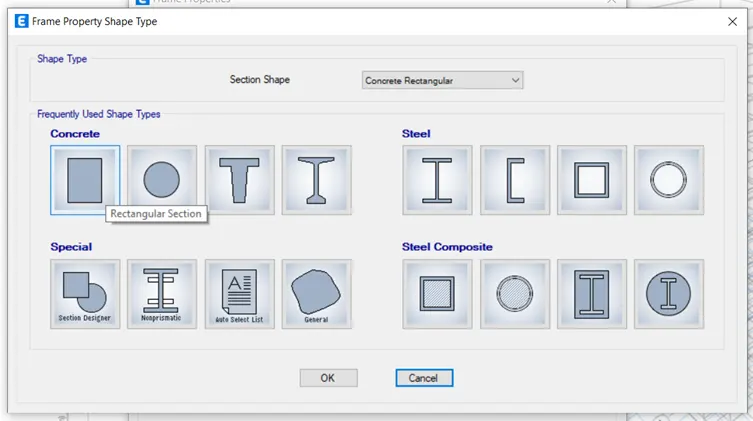

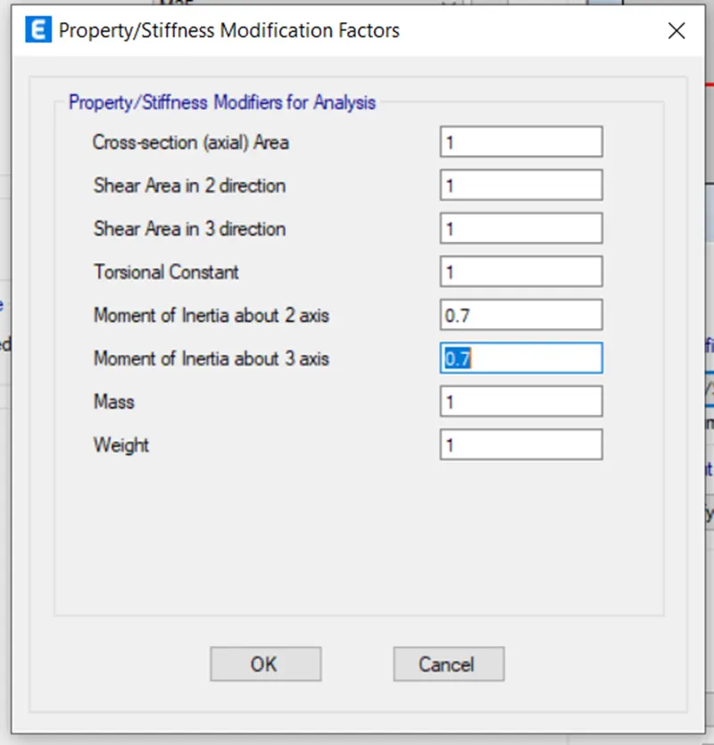
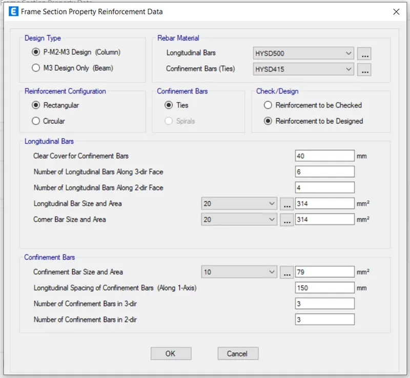
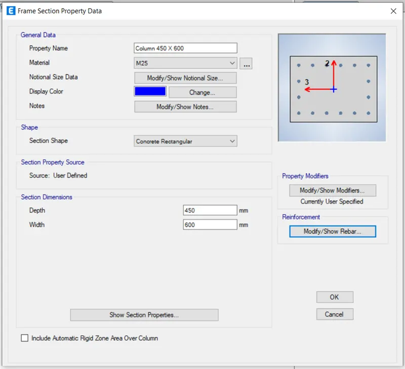

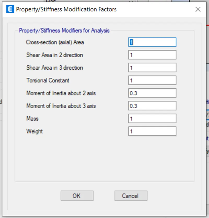
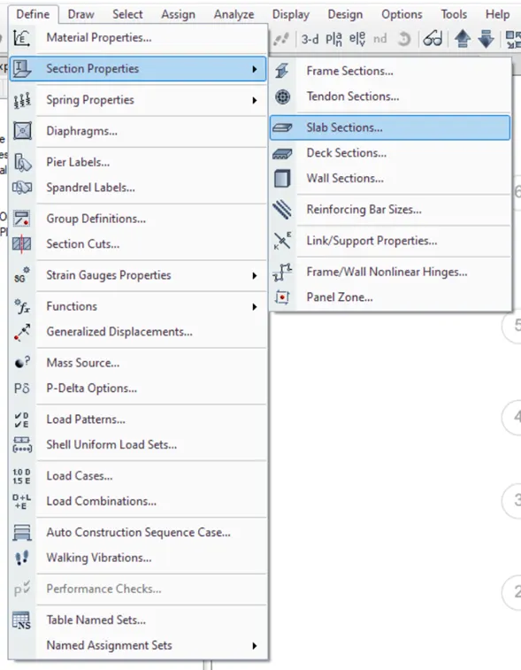
Go to define tab and select section properties in that select slab sections
Add slab of 150mm thick as per the question by clicking on Add new property
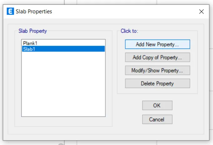
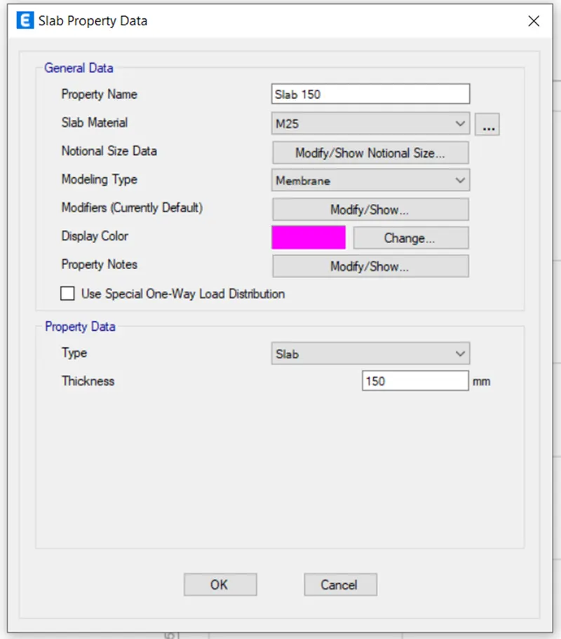
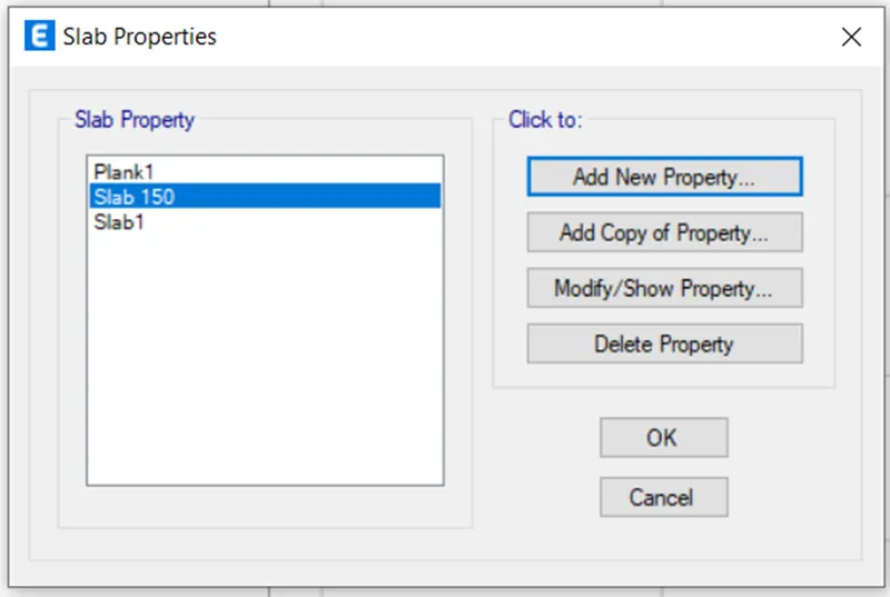
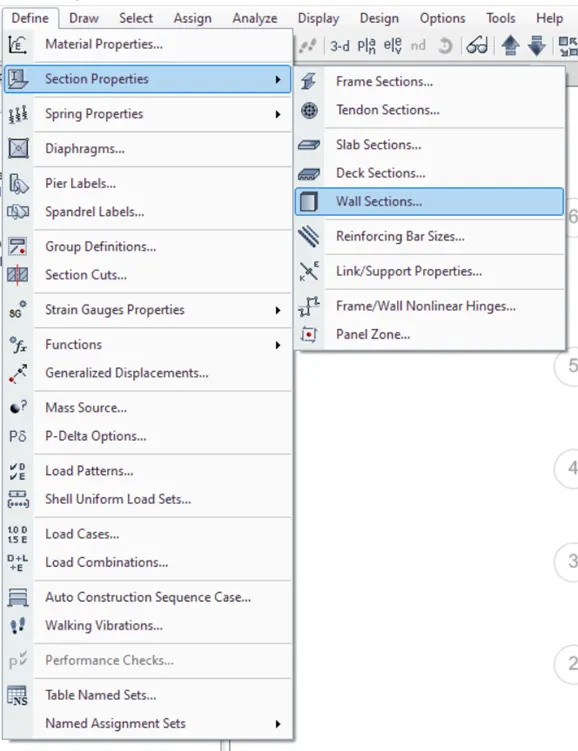
Go to define tab and select section properties in that select wall sections
Add wall of 300mm thick as per the question by clicking on Add new property
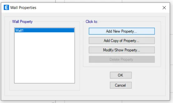
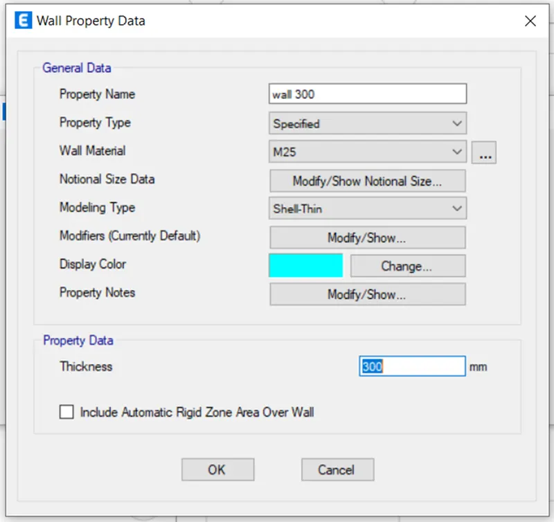
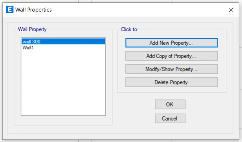
Step 5 : Draw the column 450 x 600 at each intersection of the grid by selecting Quick draw column
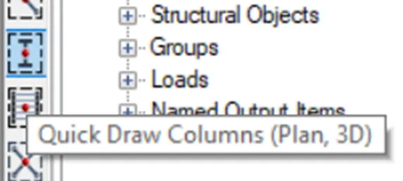
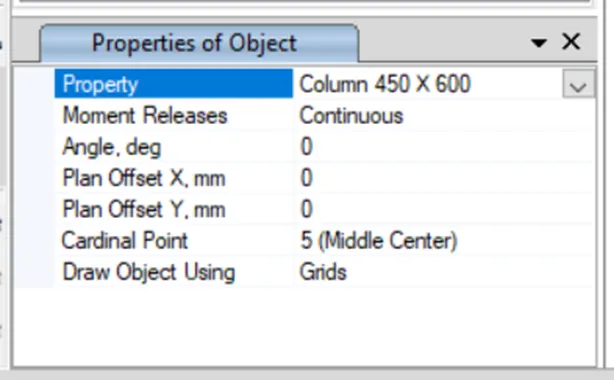
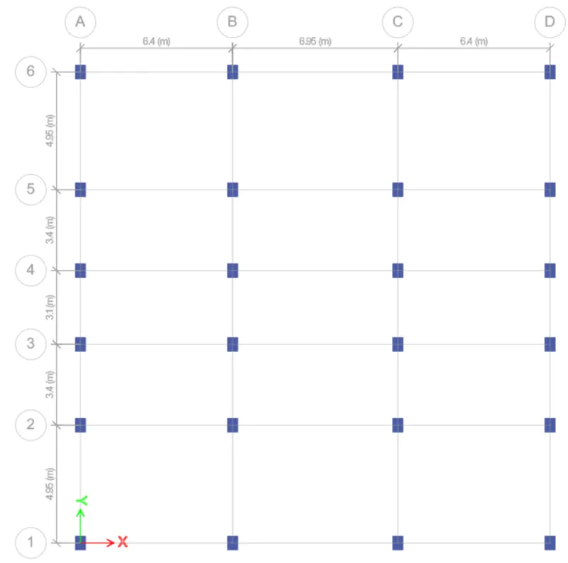
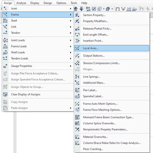
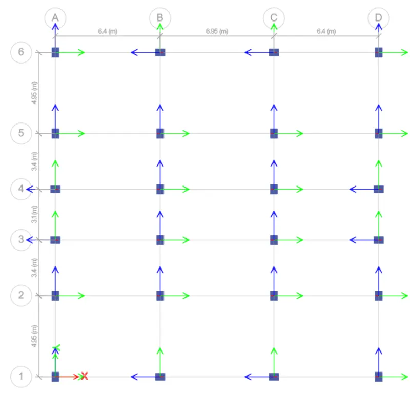
Go to Assign tab in that select frame and select local axes and rotate the columns wherever needed by 90 degree
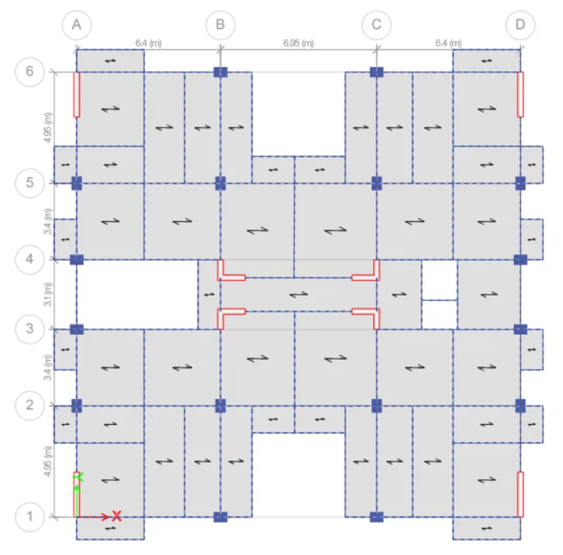
Draw the beam 400 x 500 at grid line by selecting Quick draw beam
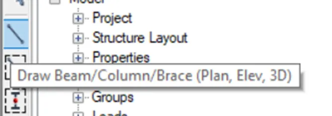
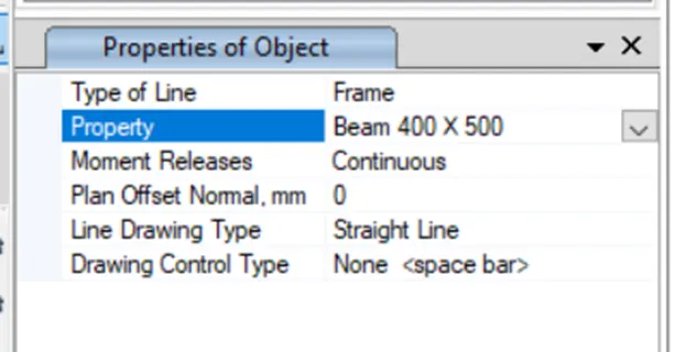
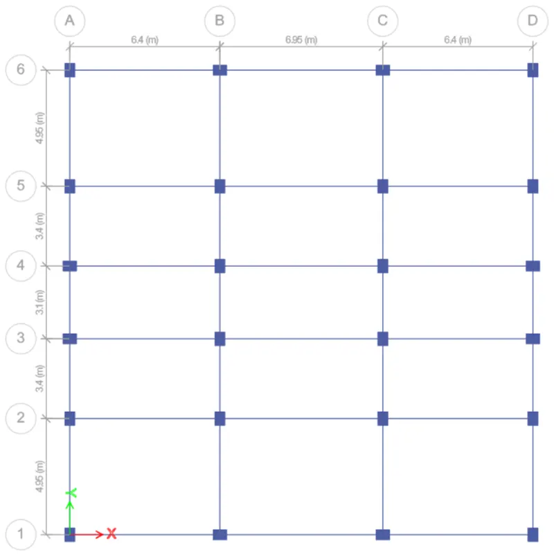
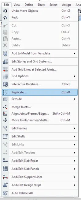
Now by using replicate, move and divide draw the beam layout as per the given plan
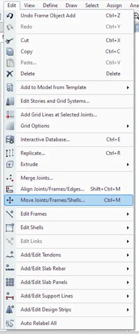
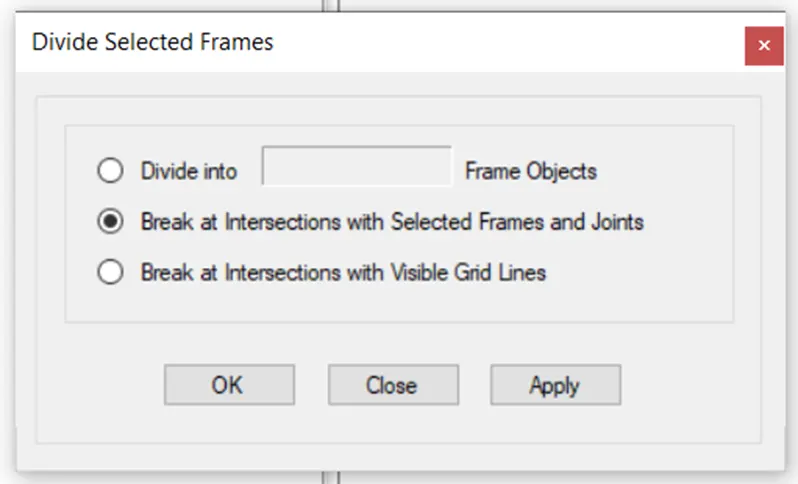
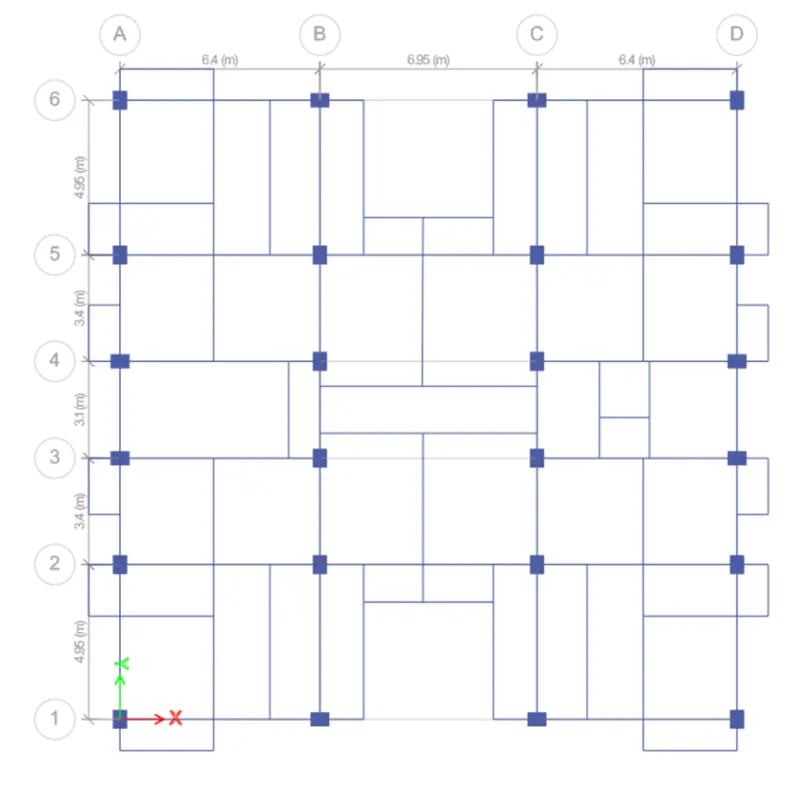
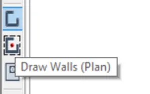
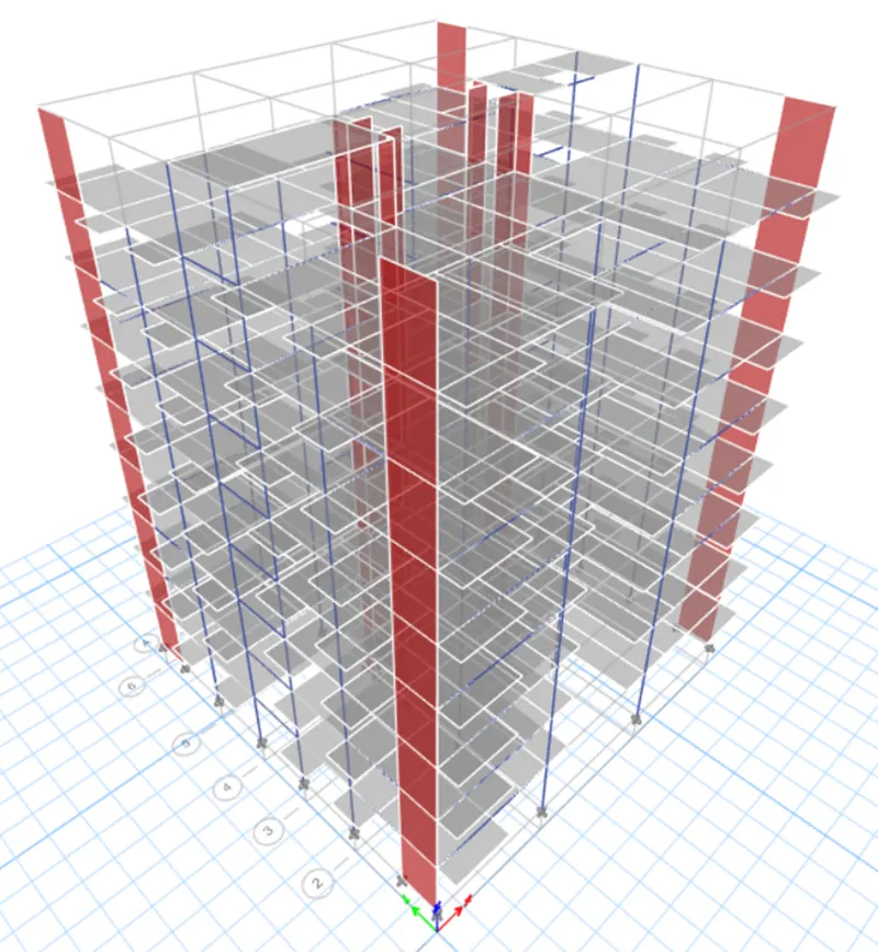
Draw the wall 300 wherever required by using draw walls
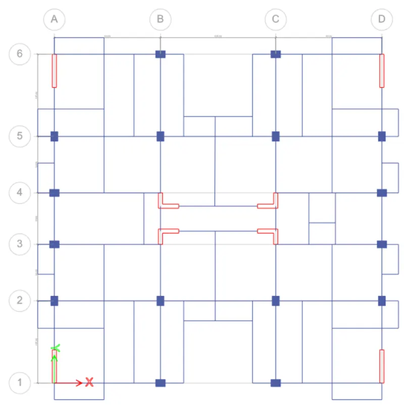
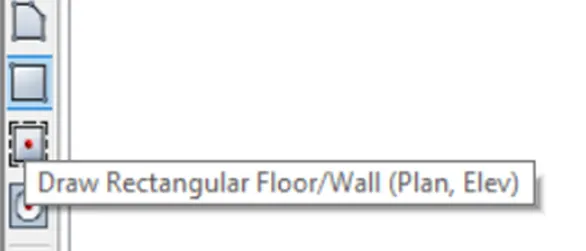
Draw slab of 150mm by selecting quick draw floor
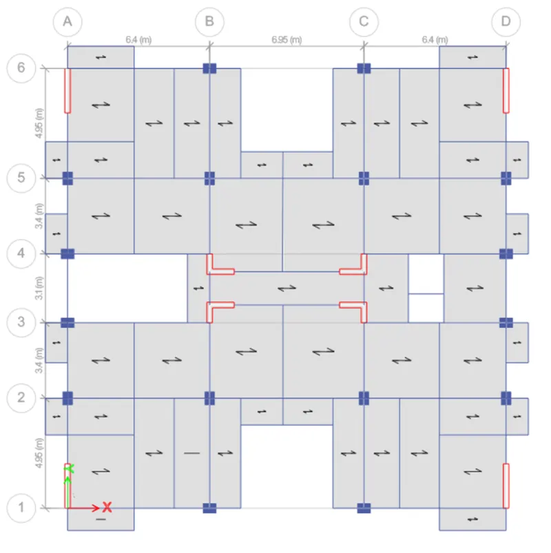
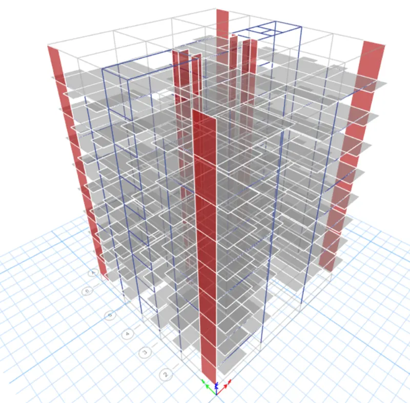
Step 6 : Go to ground floor and select all the joints
Go to assign tab select joint in that select restaints and select pinned support for all the directions and click on apply
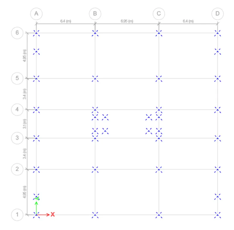
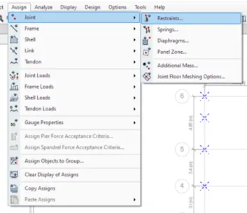
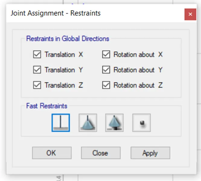
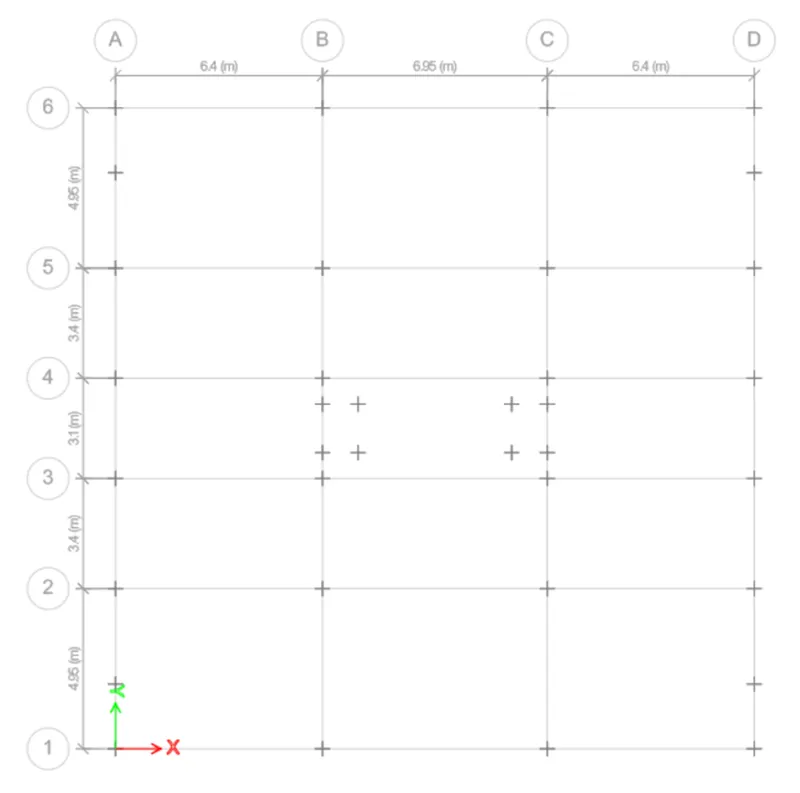
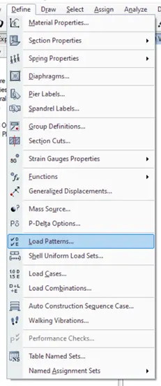
Step 7 : Go to define and select the load pattern
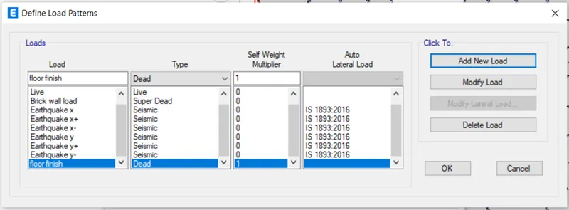
Add the loads like dead load, live load, brickwall load and earthquake load both in x and y direction in positive and negative direction
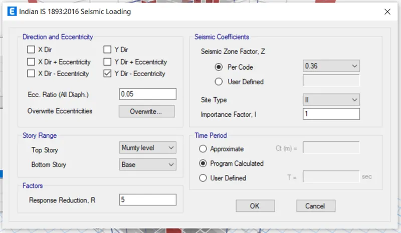
Click on modify lateral load of all earthquake loads, set a range from base to mumty floor, seismic zone factor as 0.36, importance factor as 1, site type as II and time period as program calculated
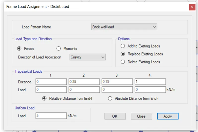
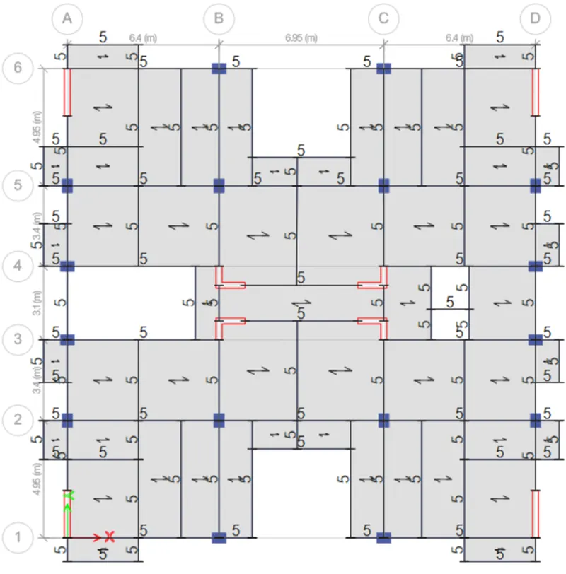
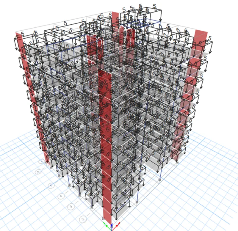
Step 8 : Assign brick wall load to all the story
Give the brick wall load as 5KN/m for all the stories
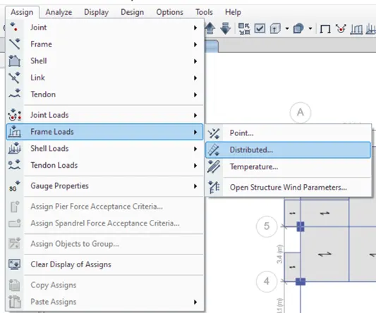
By selecting the beams go to assign tab and select frame load and do the settings accordingly and click apply
Step 9 : Assign live load and floor finish to all the story
Give the live load as 2.5KN/msq for all the stories
By selecting the slabs go to assign tab and select shell load and do the settings accordingly and click apply
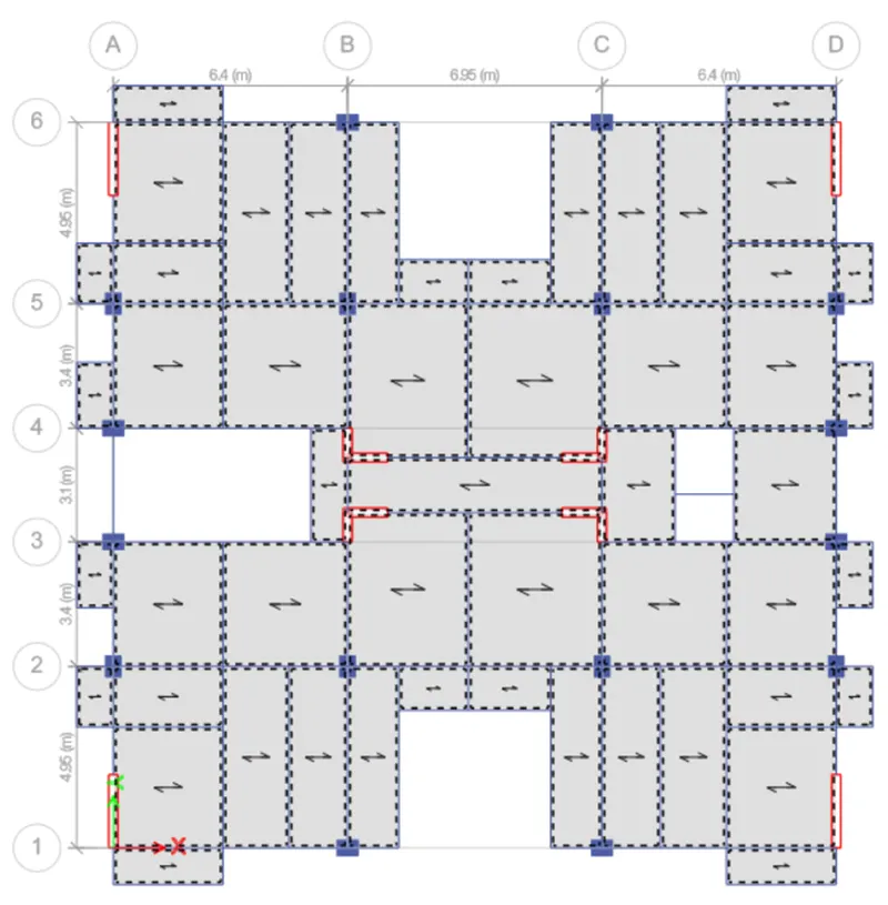
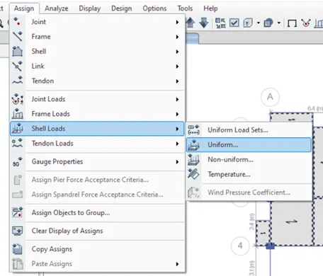
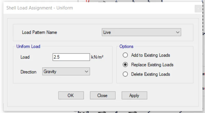
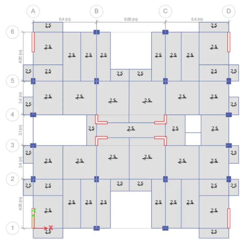
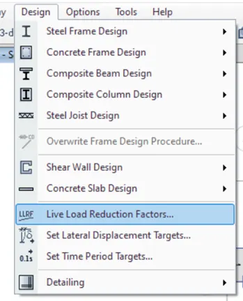
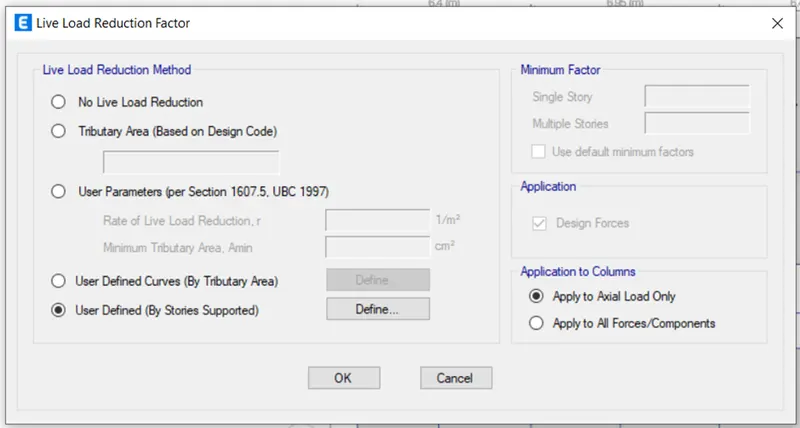
Step 10 : Go to design tab select live load reduction factor
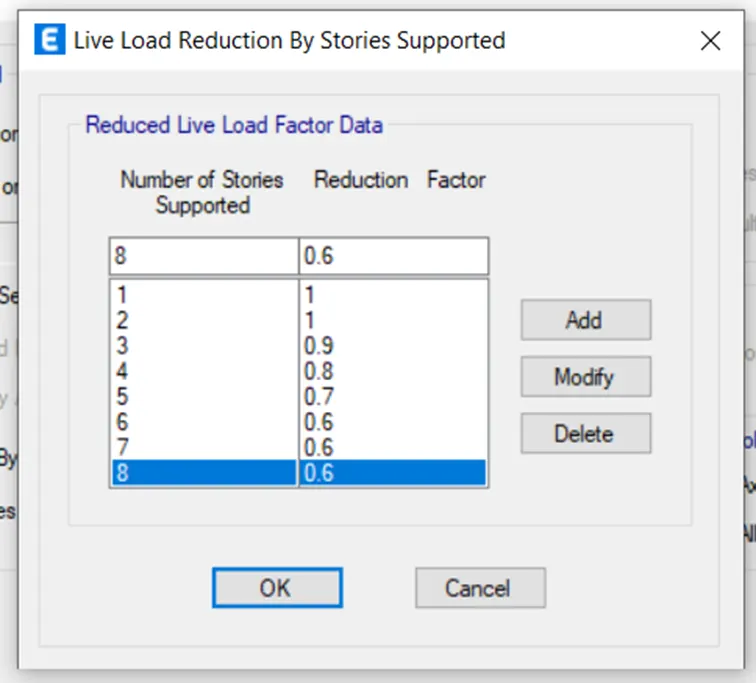
Add the reduction factor from first floor to mumty level by reducing 10% for each floor
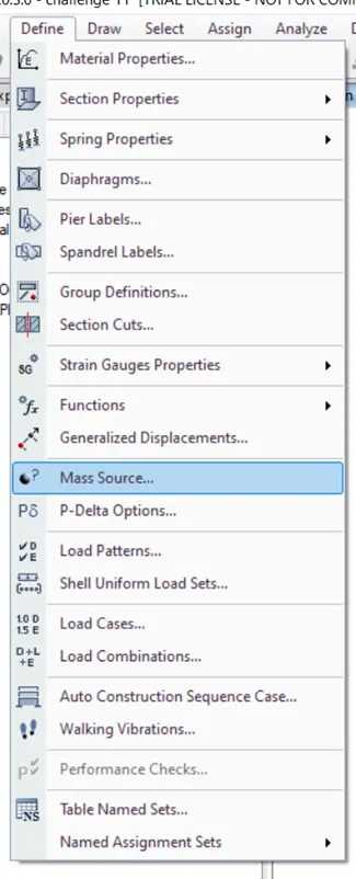
Step 11 : Go to define tab and select mass source and modify the mass source
Add the required load and assign the load to the model
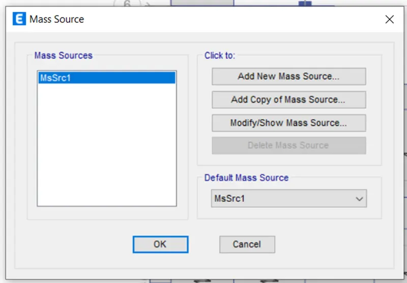
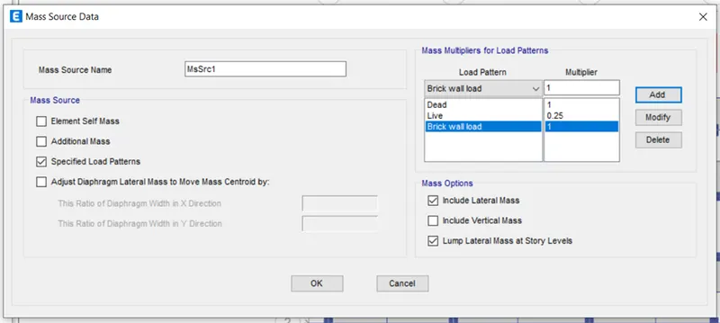
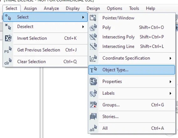
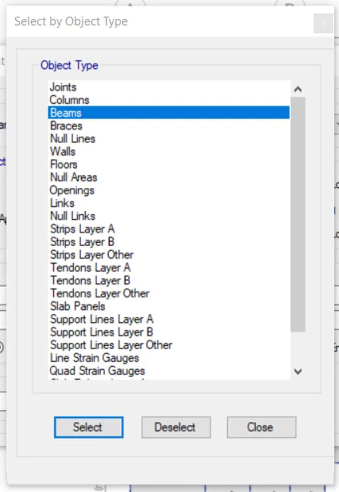
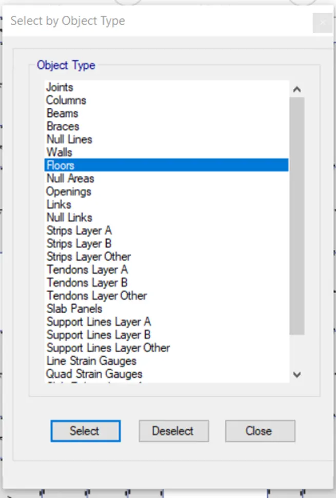
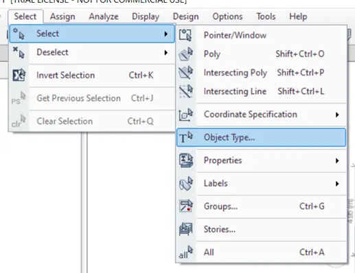
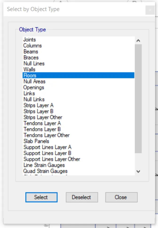
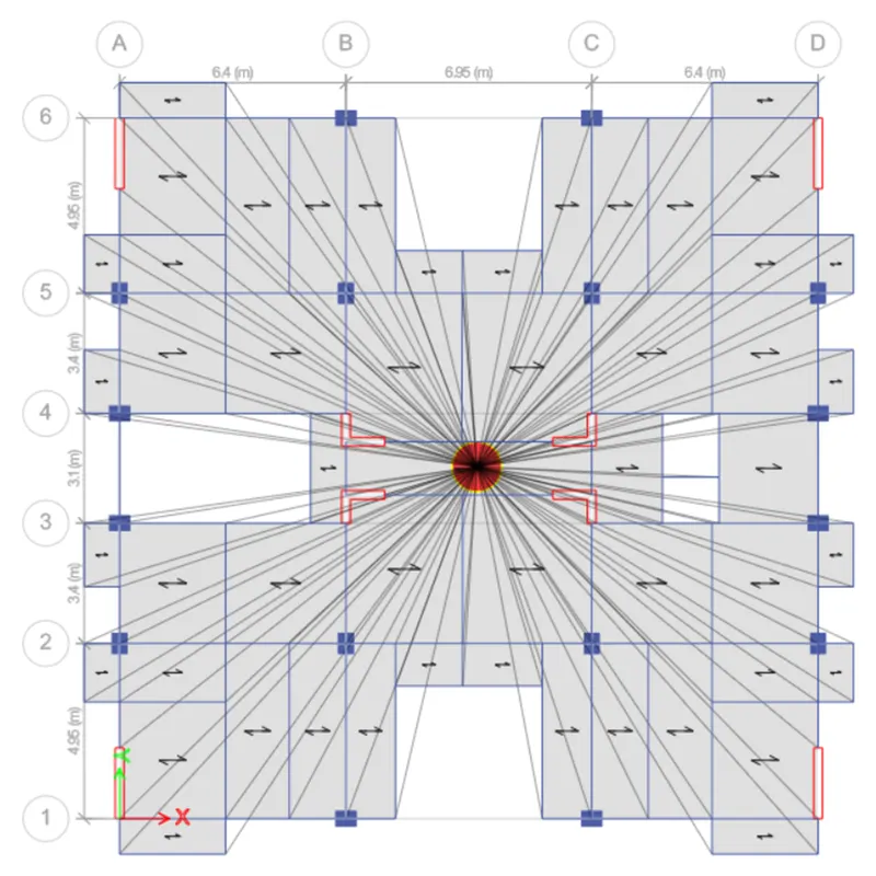
Step 12 : To create the diaphragm to the shell go to select in that select object type and in that select floors and click select and preess close
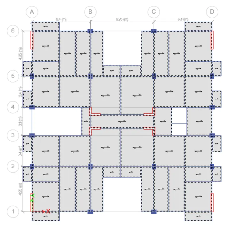
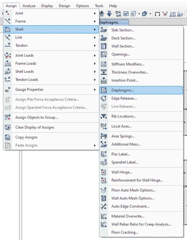
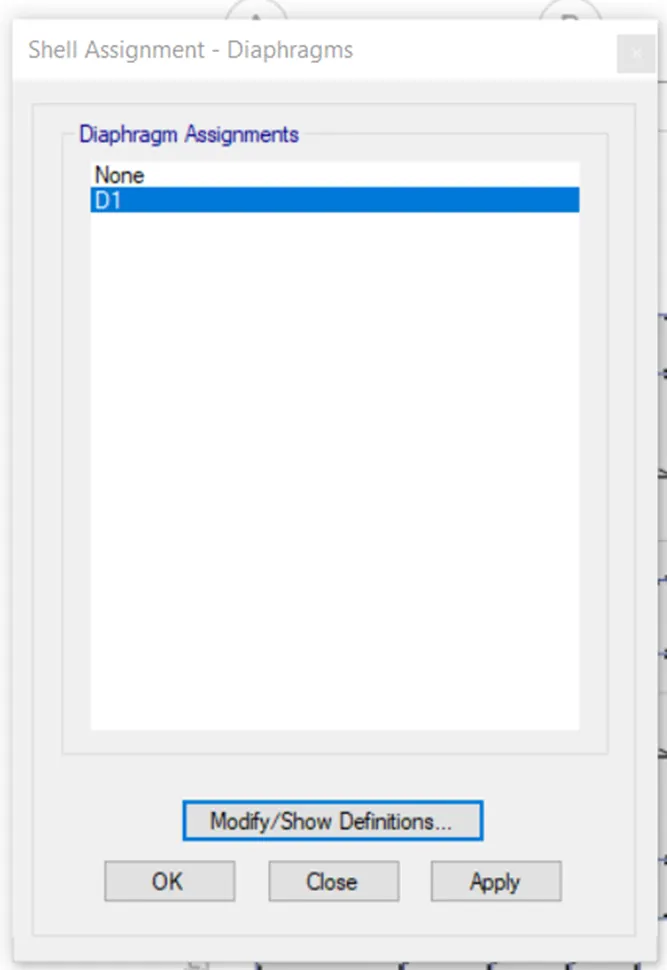
Go to assign tab select shell in that select diaphragms and select D1 and click ok
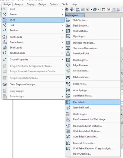
Step 13 : To check the pier label
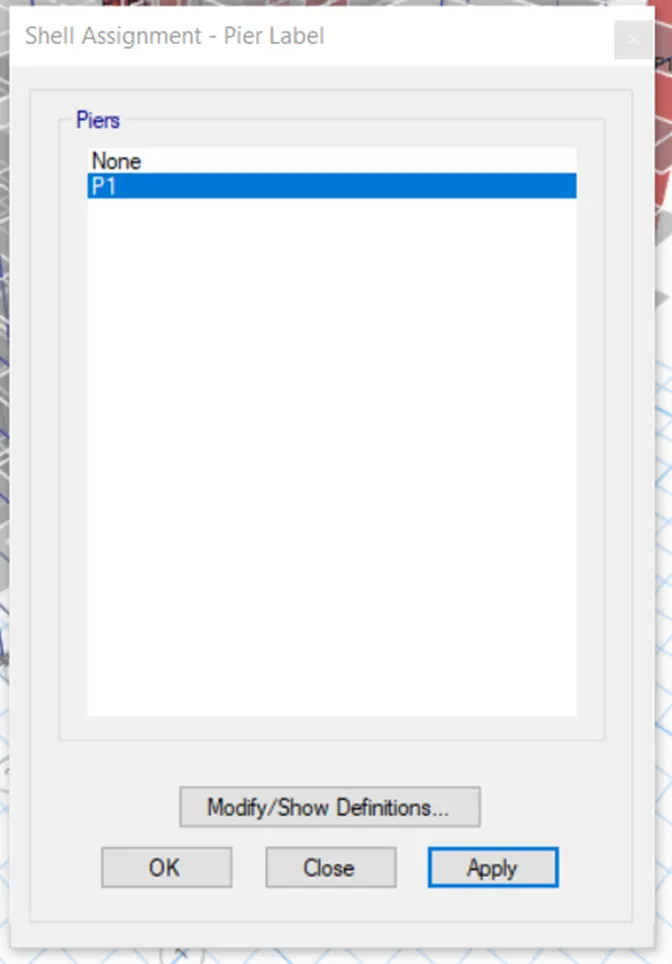
Go to assign in the select shell in that select pier label
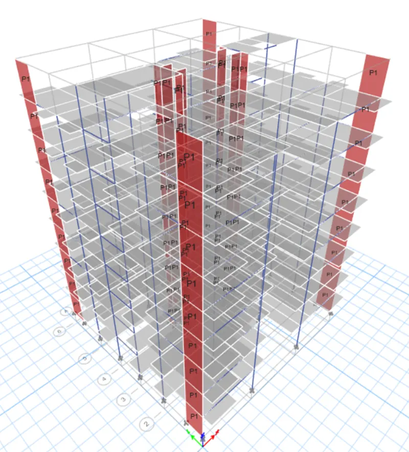
Before going to shear wall design we have assign names for shear walls
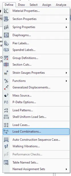
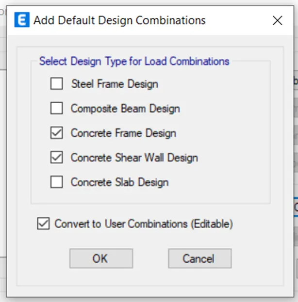
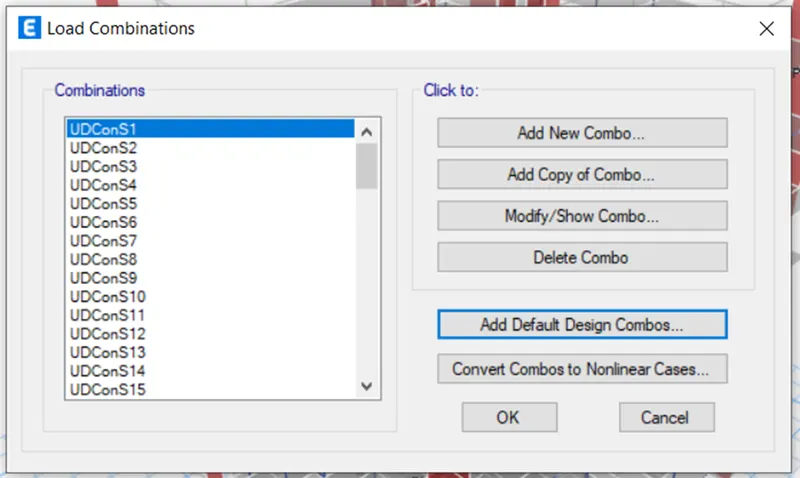
Step 14 : Go to define tab and select load combinations in the dialogue box click on add defaut design combinations in the dialogue box select Concrete frame design and concrete shear wall design and click ok
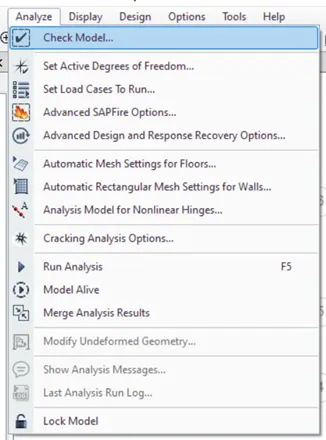
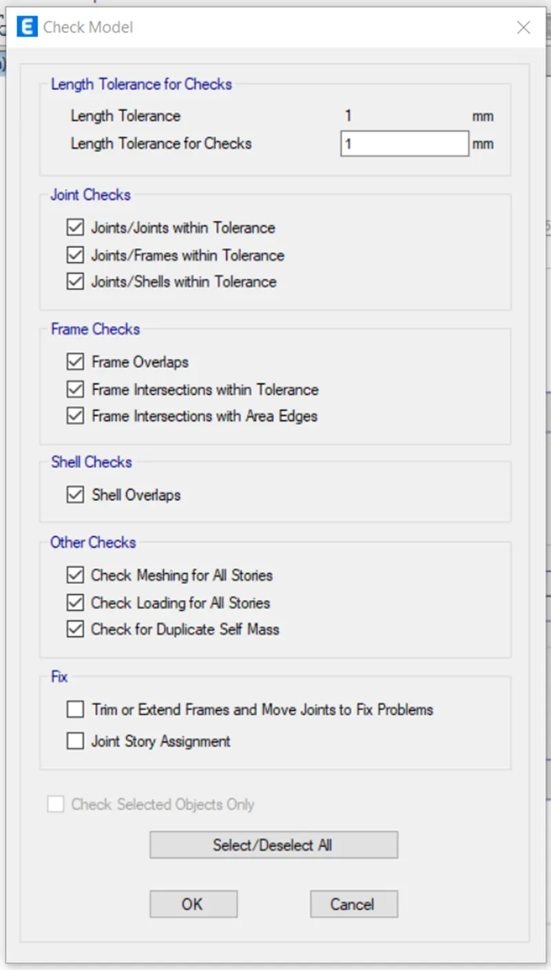
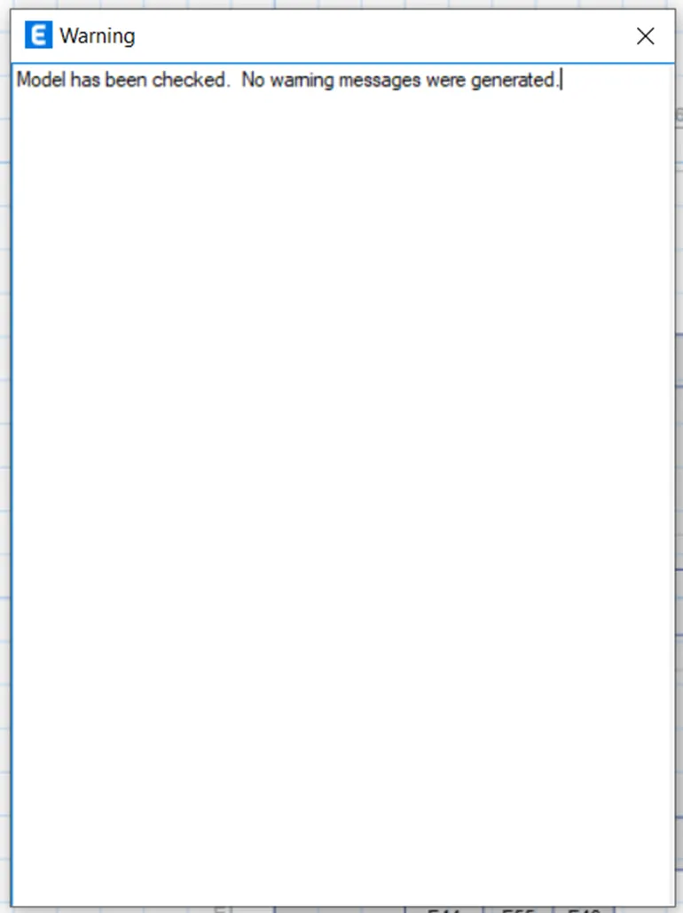
Step 15 : Go to Analyze and select check model and analyze the model for errors
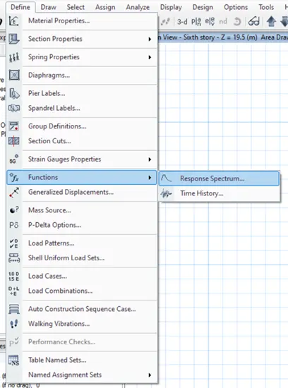
Step 16 : Go to define tab select functions in that select response spectrum
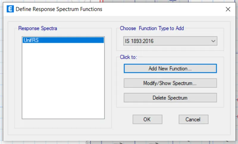
After selecting response spectrum a new dialogue box will appear in that choose IS 1893 – 2016 in choose function type and click on modify/show spectrum
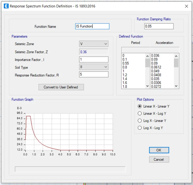
A new dialogue will appear in that give function name as IS Function and remaining details same as per the code so no need to change
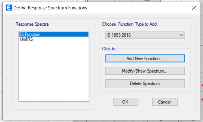
Step 17 : Go to define tab in that select load cases
In the dialogue box appeared select add new load cases and add the required load cases
Add detail of load case in the load case data
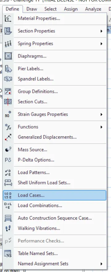
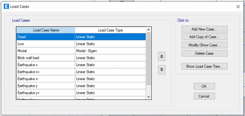
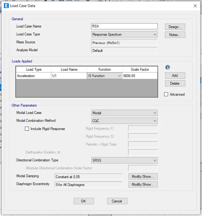
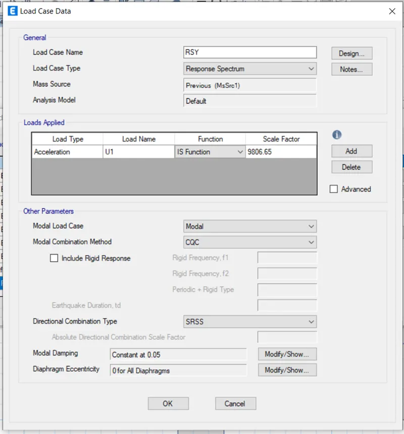
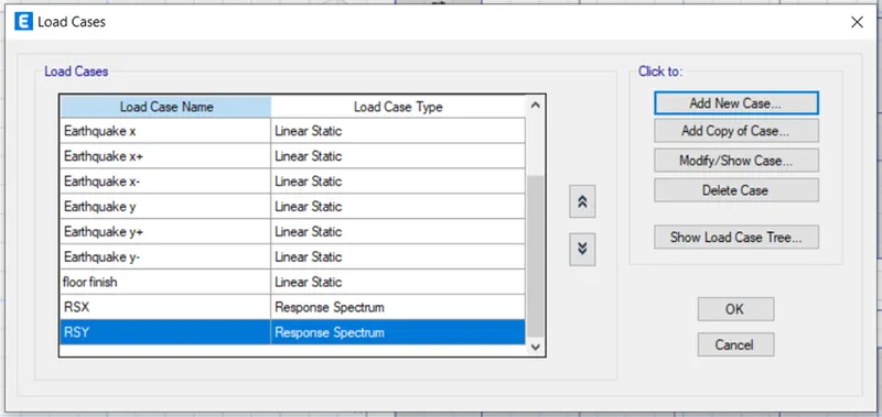
Step 18 : Go to analyze tab in that select run analysis the model will get analyzed and results will occur
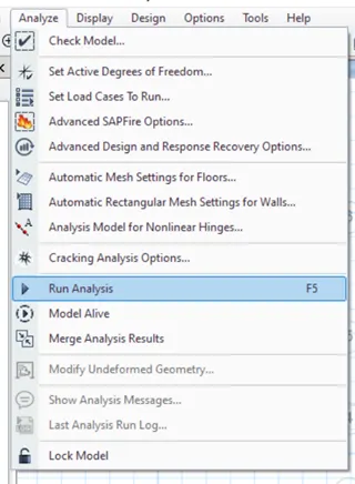
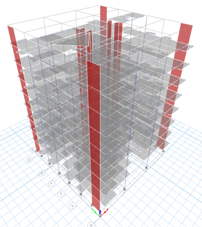
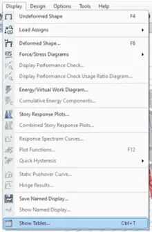
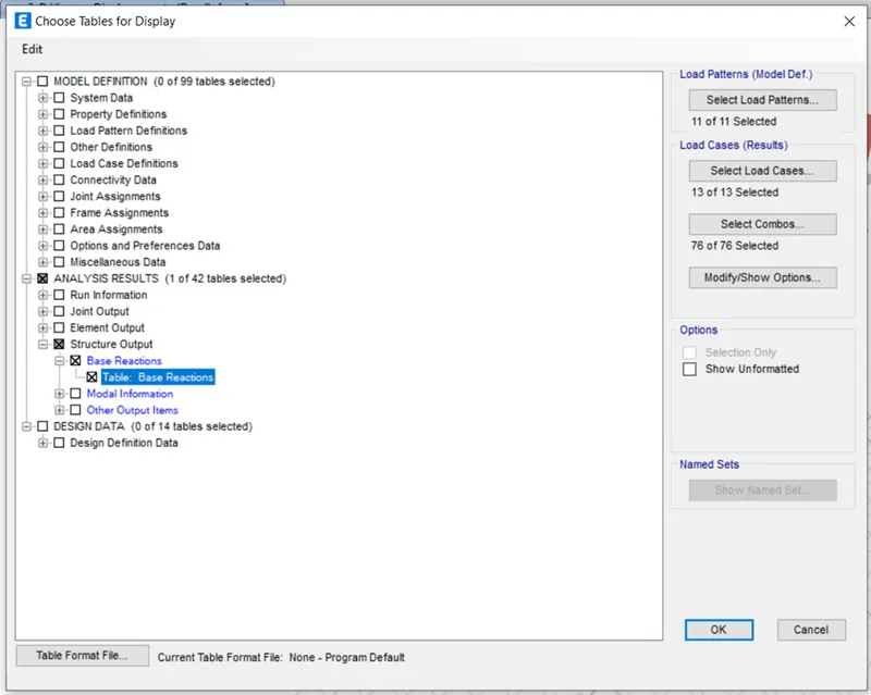
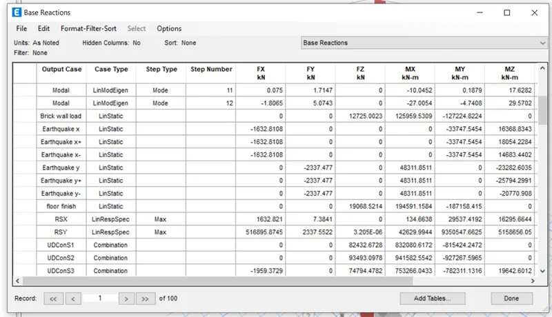
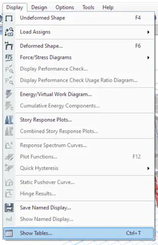
Step 19 : Go to display tab select show tables and select base reactions and click ok
Base reaction table as been appeared
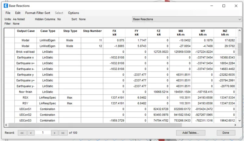
Now we have to check EQ should be closer to RS, So we have to calculate in both x and y direction
(EQ / RS) x scale factor factor of response spectrum
(1632.81/1337.41)x9806.65 = 11972.69 KN in x direction
(2337.477/6.048)x9806.65 = 3790148.615 KN in y directon
Put the above values as scale factor for response spectrum at both x and y direction in the load case data
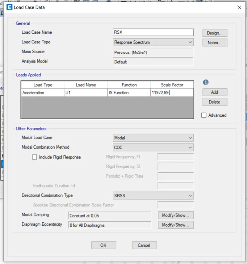
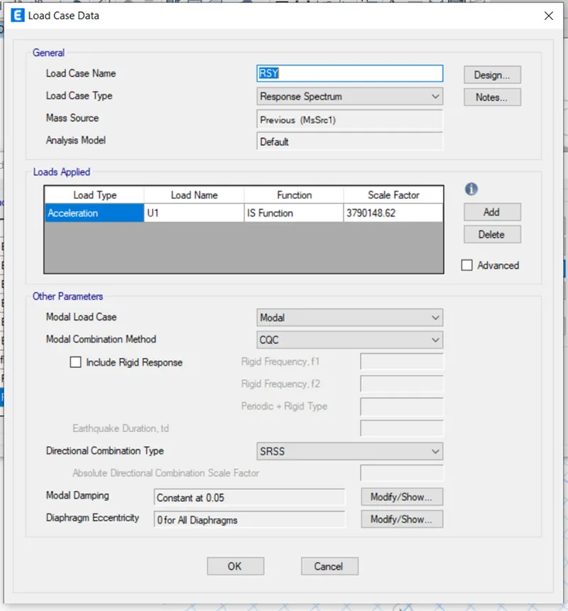
Again run the analysis and then again select base reaction table the EQ is closer to RS
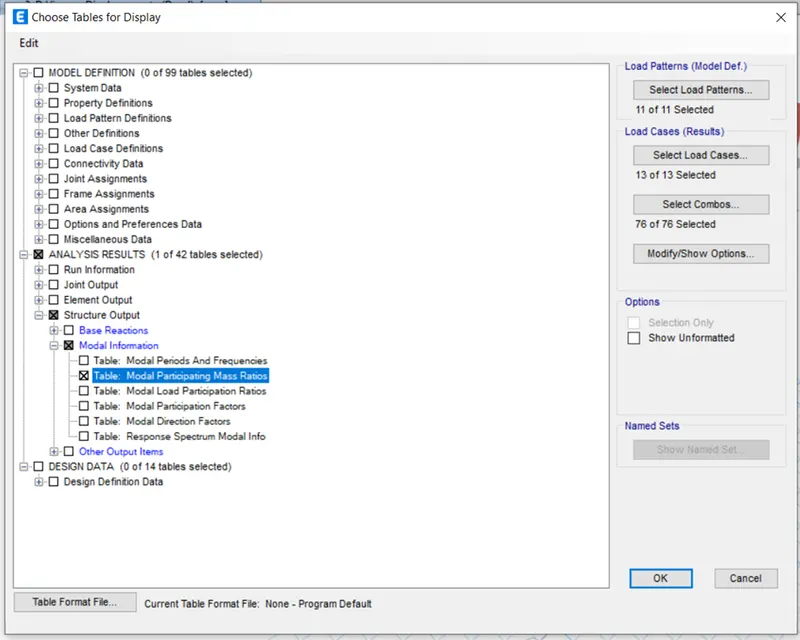
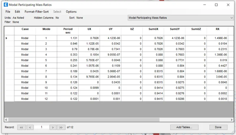
Step 20 : Go to display tab select show tables and select modal participating mass ratio and press ok
Modal participating mass ratio table as been appeared
Step 21 : Go to display select and select story response spectrum and select story response as maximum story drifts in both x and y direction and it should be not more than 4%
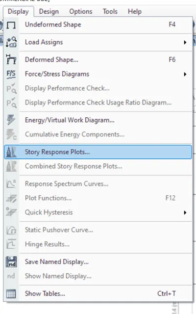
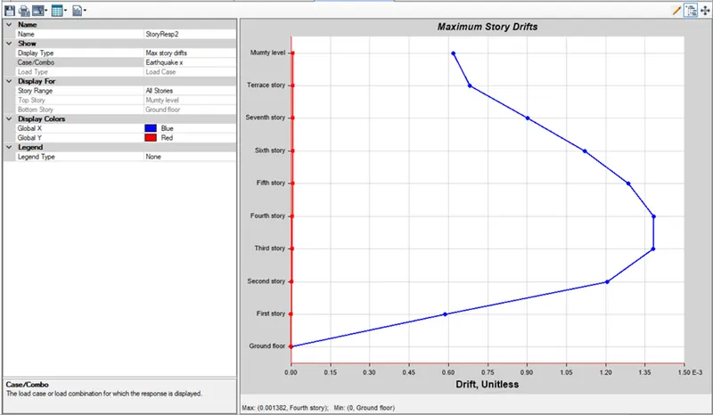
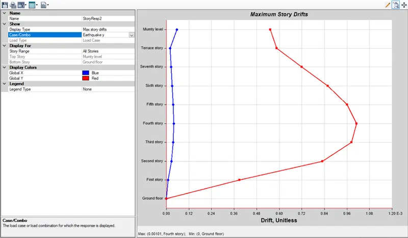
Step 22 : Now go to plan view and select ground floor
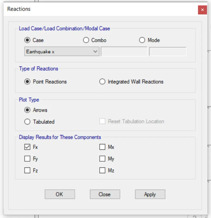
Go to tab and select reactions tab and select earthquake load toward x direction in the load case and click ok. Now base shear reaction will appear
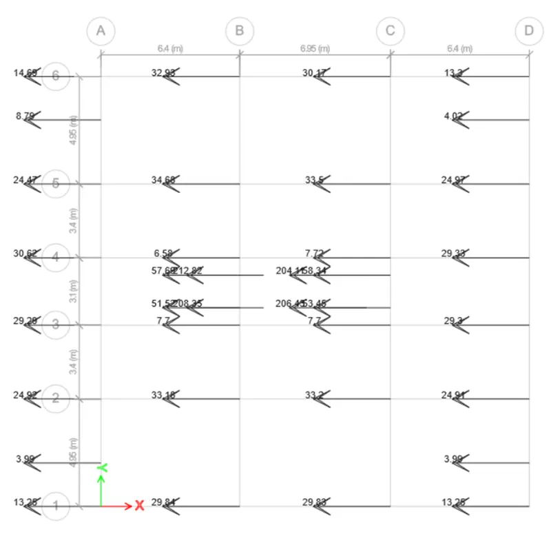
When we divide the base shear taken up by the shear wall divided by the total base shear of the building we will get percentage taken by shear wall and if that is less that 80% then more shear wall should be added to the structure
RESULT :
The given challenge is completed by using necessary tools from ETABS software