Structural Modelling using Etabs 2018
The architectural drawings for a G+7 residential building in zone 5 have been provided. The floor plan is the same for all 7-floor levels. Possible column positions have also been provided. Conceptualize a framing plan layout and then model the building in ETABS. The following architectural drawings have been provided:
· Typical floor plan – The location and thickness of the brick walls and the use of the
space (for estimating live load) can be obtained from this plan
· A building section through the staircase and lift core is provided
· Parking layout on the ground floor – the column/shear wall arrangement must not
obstruct entry/exit of vehicles.
The following loadings are to be taken into account:
· Brick wall made of AAC blocks (650kN/m3)
· Finishes – floor tiles of 75 mm thickness (1.5kN/m2)
· Live loads as per IS 875 part 2
· Water tank of 20 KL above the staircase at mumty level
· Lift Machine room at mumty level above lift core
The structural model must comply with provisions of IS 1893 and IS 13920.
Run a modal response spectrum analysis and check analysis results of the ETABS model for inter-storey drift requirements, vertical & planar irregularities, minimum shear wall requirements, maximum axial load ratio for column and shear walls, the effective moment of inertia for beams and columns etc.
Please note that the column positions shown in the architectural typical floor plan are only to provide an initial starting point for modelling. Participants will have to change its size, introduce shear walls, and add new vertical elements after running the analysis. You will have to run the analysis multiple times until a structural model is obtained that meets structural code requirements without compromising architectural functions. Also, there is no one ‘correct’ structural system for this challenge. There can be multiple possible solutions to this problem.
AIM
- To conceptualize a framing plan layout and model the given G+7 building situated in zone 5 in ETABS.
- To develop the structural model that complies with provisions of IS 1893 and IS 13920.
- To run the modal response spectrum analysis and check the ETABS model’s results.
INTRODUCTION
- ETABS is an engineering software product that caters to multi-story building design and analysis.
- Modelling tools and templates, code-based load prescriptions, analysis methods, and solution techniques, all coordinate with the grid-like geometry unique to this class of structure.
- Fundamentals to ETABS modelling is the generalization that multi-story buildings typically consist of identical or similar floor plans that repeat in the vertical direction.
- Once modelling is complete ETABS automatically generates and assigns code-based loading conditions for gravity, the seismic, wind, and thermal forces.
- Users may specify an unlimited number of load cases and combinations.
- Outputs and display formats are also practical and intuitive. Moment, shear, and axial force diagrams, presented in 2D and 3D views corresponding data sets, may be organized into customizable reports.
- Here, in this challenge, we are going to model an entire G+7 building with the floor plan using ETABS software.
PROCEDURE
The AutoCAD file along with the plan and section screenshots has been attached to the question.
Below is the Architectural plan and the sectional elevation of the building to be modelled and analysed using ETABS.
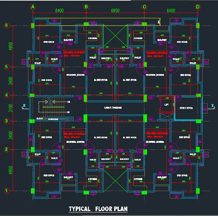
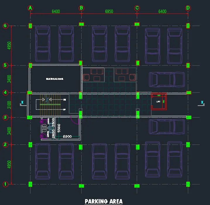
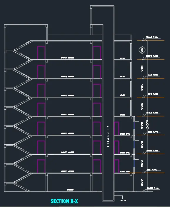
Open the ETABS software and specify the codes and specifications to be followed for the project.
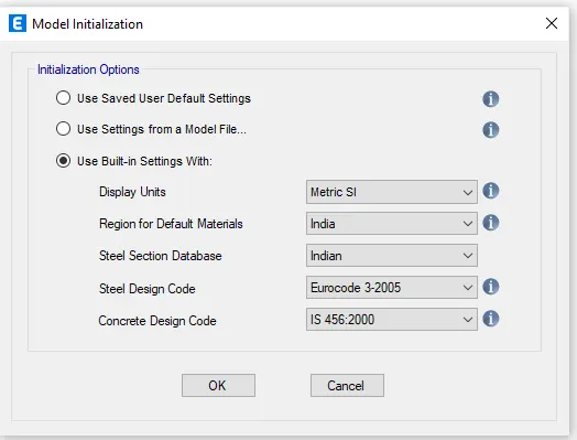
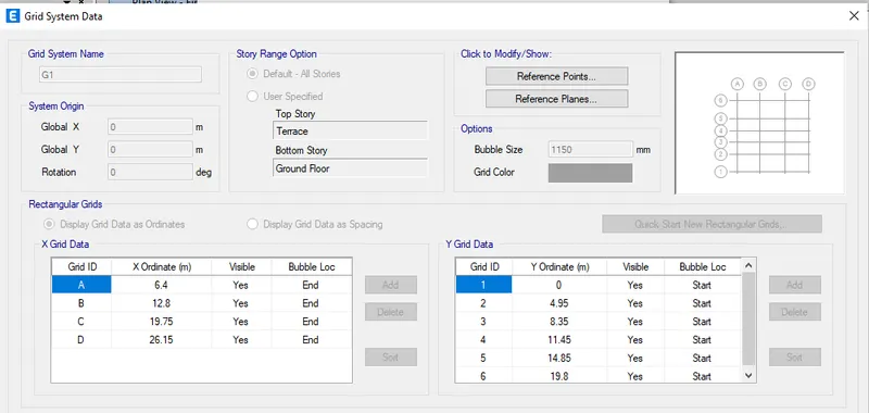
Specify the grid and the storey data as per the given Architectural drawings.
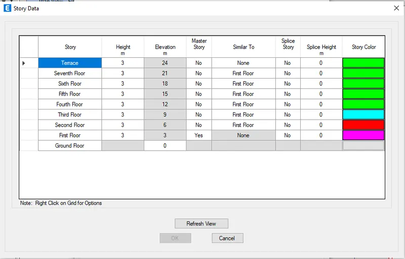
Specify the height of each floor, set the First floor as the master story and all other floors similar to the first floor.
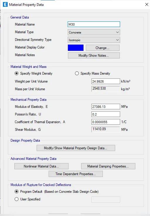
Click on Define Tab>material properties
Click on add new material
Add M30 grade concrete
Check material property data
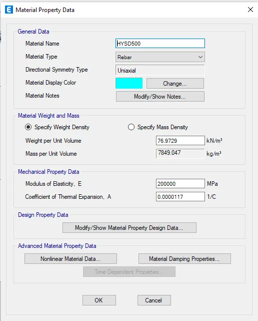
Add rebar Fe500
Check material property data of the HYSD bar
Add rebar Fe415
Check material property data of the HYSD bar
Go to define>section properties>frame sections
Click on Add new property
Select the rectangular concrete and click ok
Add new beam and column frames
Change the property name as per given data B250x450> change material to M30
Enter the depth and width of the sections
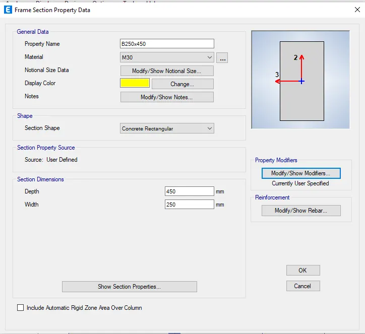
Click on Modify/show rebar>to enter the rebars types and numbers
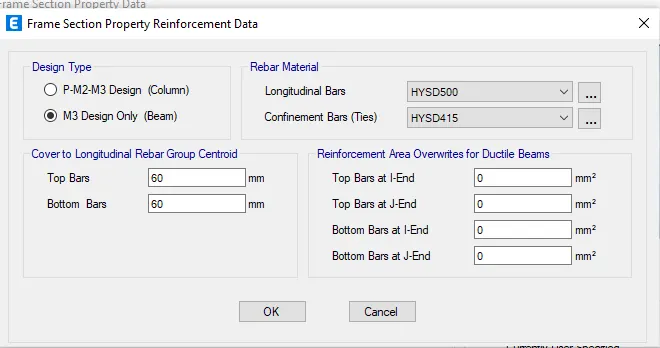
Click on M3 design only
Change longitudinal bars to Fe500 and Tie bar types to Fe415
Again on frame sections> Add new property
Select the rectangular concrete section> click on OK
Rename the property as B250x300> change material to M30
Enter the depth and width of the sections
Click on Modify/show rebar>to enter the rebars types and numbers
Click on M3 design only
Change longitudinal bars to Fe500 and Tie bar types to Fe415
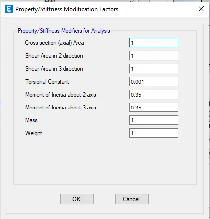
Click on property modifiers
Change the Moment of inertia about 2 axis and 3 axis to 0.35
Change the torsional constant to 0.001
Again on frame sections> Add new property
Select the rectangular concrete section> click on OK
Rename the property as C400x500
Enter the width and depth of the column
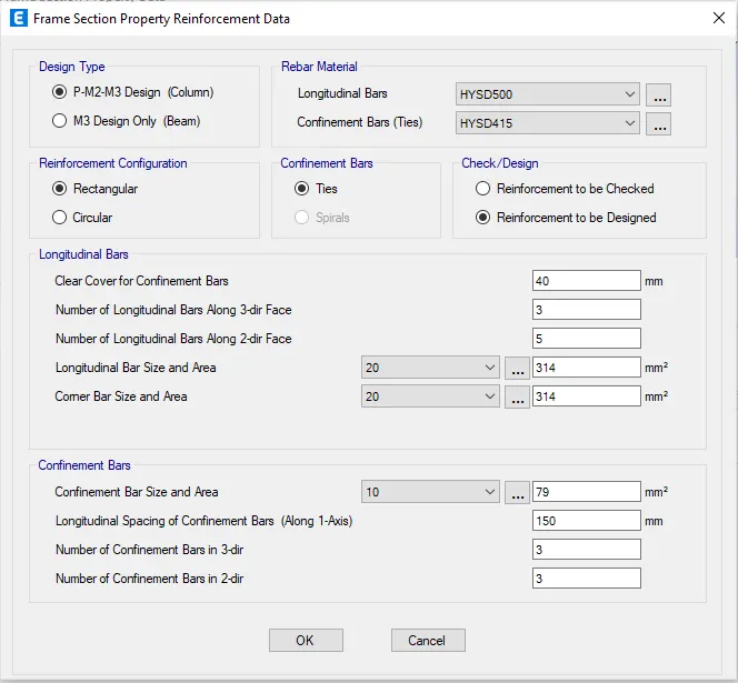
Click on modify/show rebar> to enter the bars type of columns
Click on P-M2-M3 design> Enter longitudinal and tie bars type
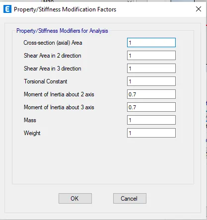
Click on property modifiers
Change the Moment of inertia about 2 axis and 3 axis to 0.7
Again on frame sections> Add new property
Select the rectangular concrete section> click on OK
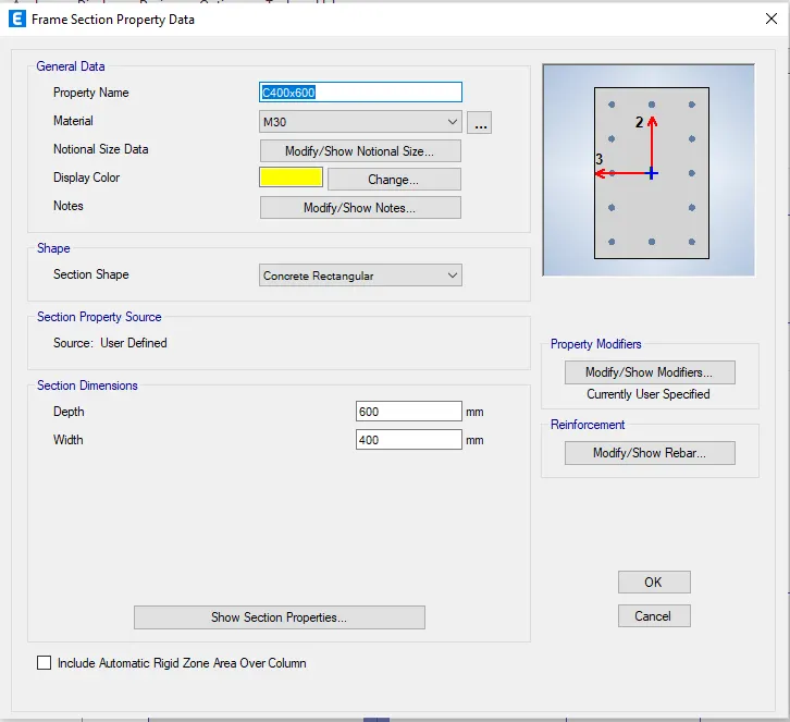
Rename the property as C400x600
Enter the width and depth of the column
Click on modify/show rebar> to enter the bars type of columns
Click on P-M2-M3 design> Enter longitudinal and tie bars type
Reinforcement to be designed> Enter the number of bars required in 2&3 direction
Click on property modifiers
Change the Moment of inertia about 2 axis and 3 axis to 0.7
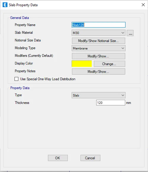
Select slab section for the slab of 120mm
Go to define> section properties> slab sections
Click on slab1> modify/Show property
Rename the slab as Slab125
Select the slab material as M30> Modelling type as "membrane"
Enter the thickness of the slab
Again Go to define> section properties> slab sections
Add new property> Rename the slab as STSlab200
Select the slab material as M30> Modelling type as "shell-thin"
Enter the thickness of the slab
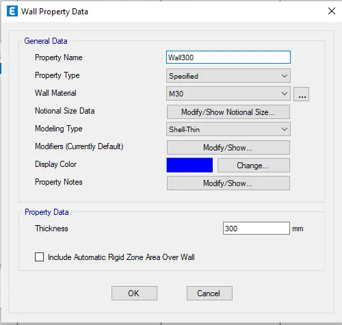
Go to define> section properties> wall sections
Add new property> Rename the wall as Wall300
Select the wall material as M30> Modelling type as "shell-thin"
Enter the thickness of the wall
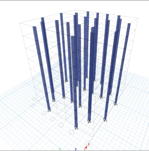
Add columns to the structure.
Go to the bottom right corner and select ALL STORIES
Click on "Quick draw columns" on the left side toolbars
Select the C400x500 from the property
Select all the columns ->all the columns will be applied to the grids
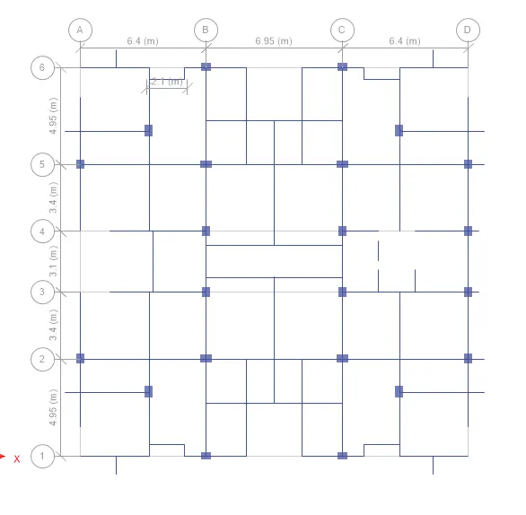
Select quick draw beams (keep the selection to ALL stories)
Select the property to B250x450
Select all the beams section> the beams will be applied
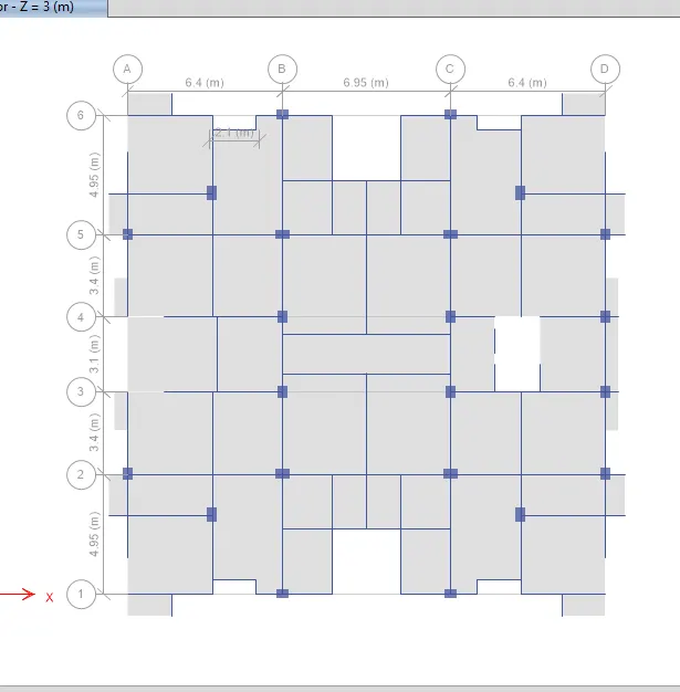
Now add slabs to the section> Select quick draw floors/Slabs
Change the property to slab 125
Change the selection to similar stories
Select all the slabs of any one floor
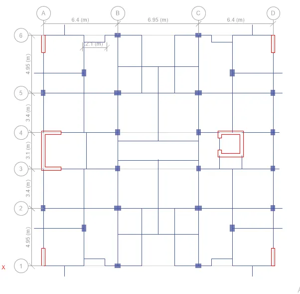
Now draw walls at the appropriate locations, delete the beam and column where the wall coincides with them
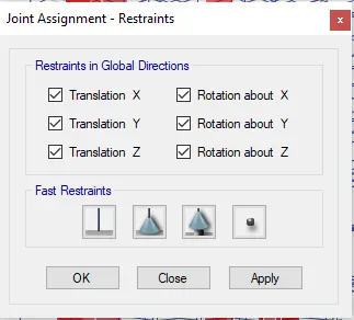
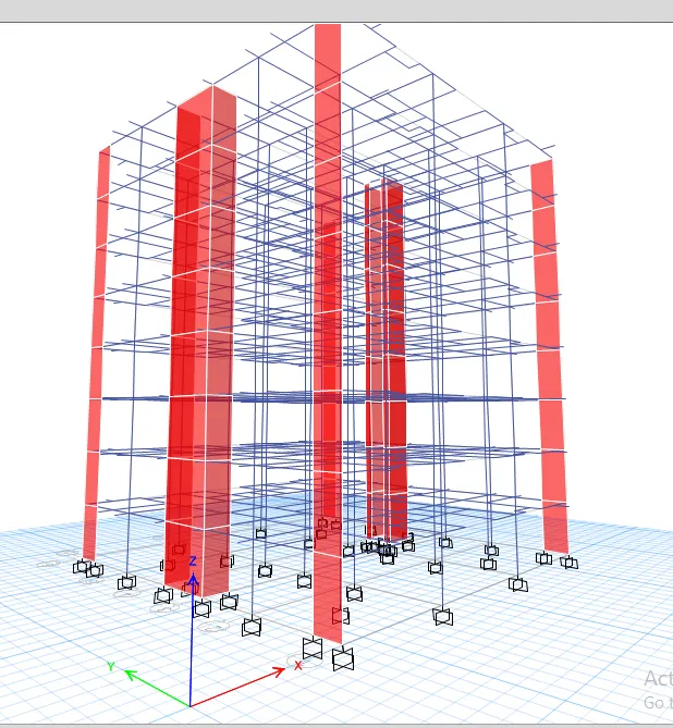
Now add joints to the base
Go to Assign bar> Joints> Restraints
Select the fixed joint
Now define load patterns
Go to Define Bar> Load patterns
Add dead load, live load, brick wall load, finishes and earthquake load
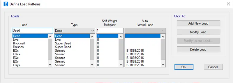
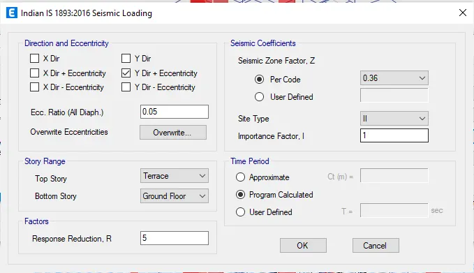
Click on earthquake loads "EQx-" > Click on Modify lateral load
Select the Load direction (X dir.-eccentricity)
Select Site II, seismic zone factor as 0.36 & time period as the program calculated
Do this for all the earthquake directions, just change the eccentricity and direction in the above
Assign the live load to the slabs and brick wall loads
Select all the slabs of any floor> Change the selection to similar stories
Go to Assign> Shell loads> Uniform
Apply the 3 kN/m2 live load for the staircase portion, veranda, and lift core area.
Apply the 2.5 kN/m2 live load for the remaining portions in the residential building.
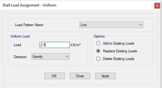
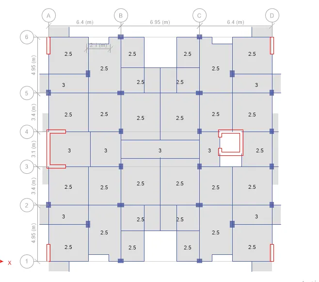
Assign the wall load to the beams
Go to select menu> object types> select beams (all beams will be selected)
Go to Assign menu> Frame load> distributed
Enter the value of 3.5kN/m
The value of 3.5 KN/m is derived from the density calculations as we are using AAC block as the masonry material.
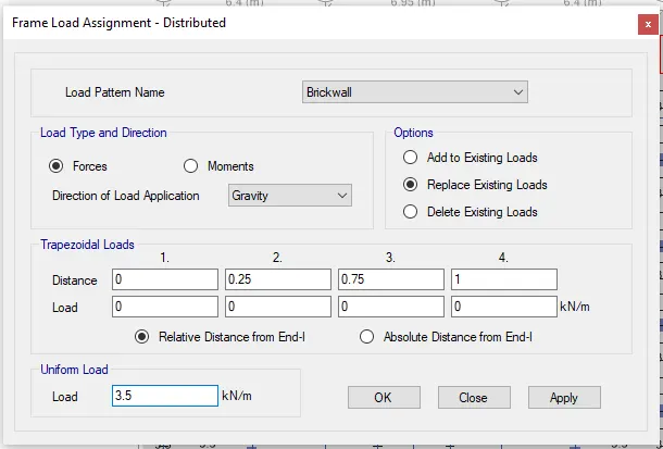
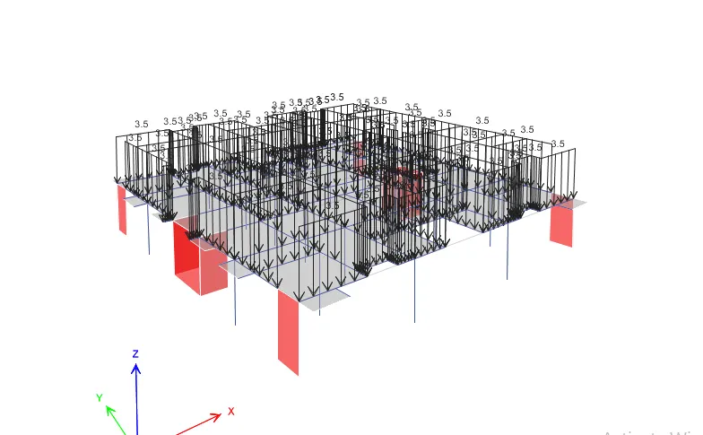
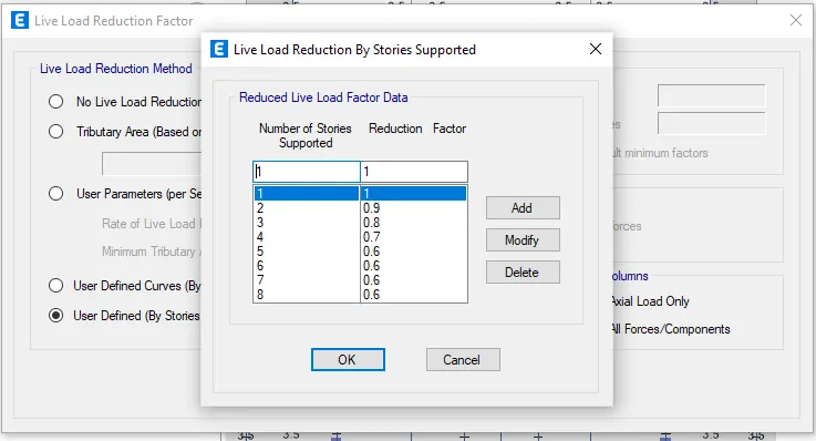
Select load reduction factor from the design option.
Now add the reduction factor by decreasing 10% from the first floor to the 7th floor.
Define mass source
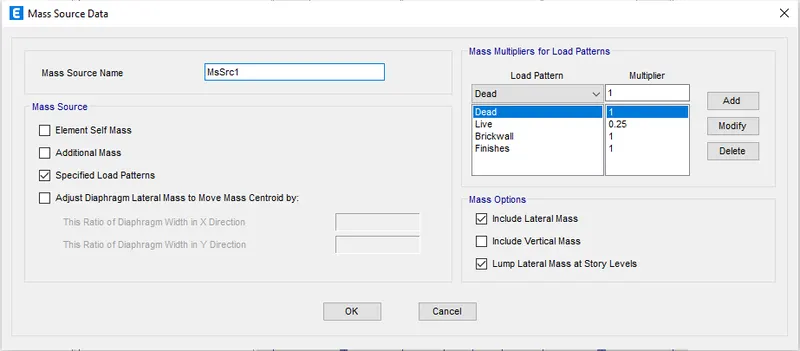
Go to Assign Menu> Mass source
Click on Modify/show mass source
Select specified load patterns
Input dead=1, finishes=1, brick wall=1, live=0.25
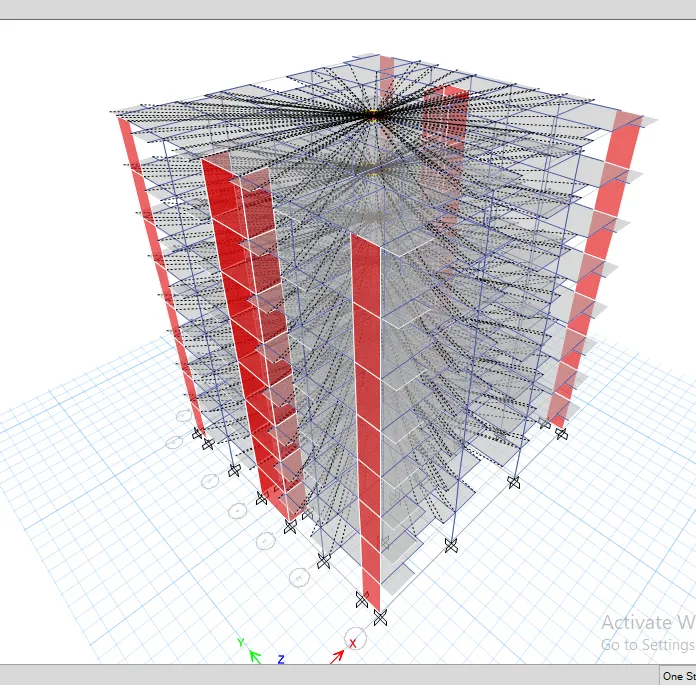
Making the diaphragm of the structure
Go to select menu> object types> select the floors
Assign> Shell> Diaphragm
Select D1 and apply
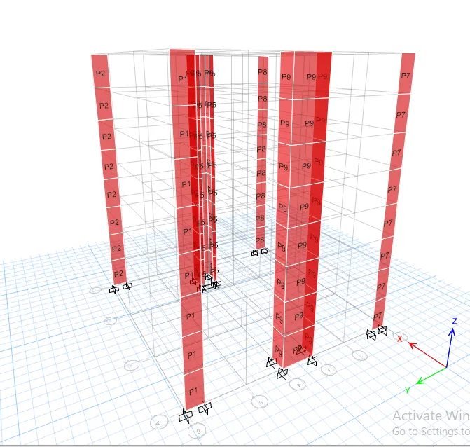
Select the pier label from the shell option.
Assign the name for each shear wall (P1, P2, P3, etc.)
Go to Define> function> response spectrum
Select IS 1893:2016 as the function type
Add new function> Rename it as RSA
Select zone V, Importance factor 1, Soil type II, Reduction factor 5, Damping ratio 0.05
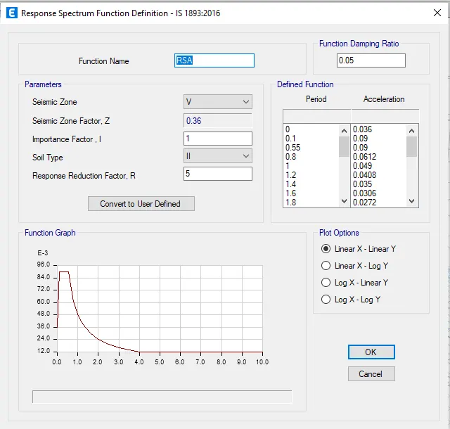
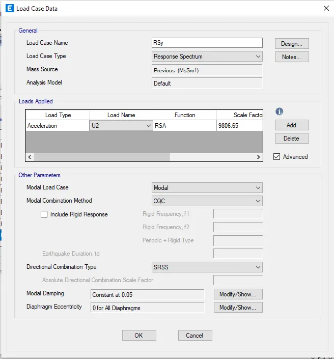
Go to Define> Load cases> Add new case
Add Response Spectrum function in X and Y direction with default scale factor
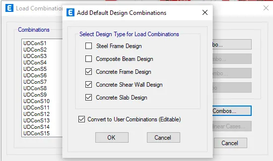
Go to define menu> load combination
Click on Add default design combos
Select concrete frame design, concrete shear wall, concrete slab section
Check the model for errors
Go to analyse menu> check model
Go to analyse menu> run analysis
Base Shear Check
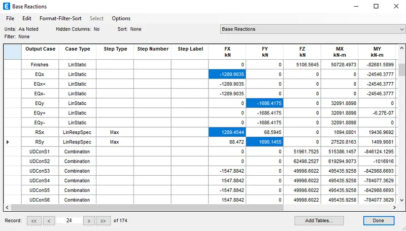
Go to model explorer> Tables> Analysis Result> Structure Output> Base reaction
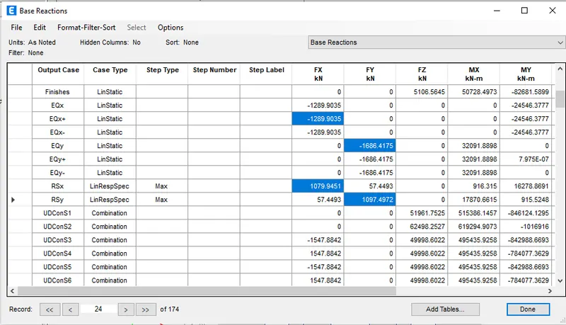
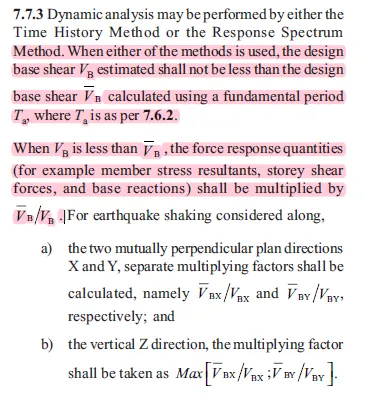
As per IS 1893:2016, the response spectrum base shear must be at least equal to that obtained by the linear analysis.
Therefore we need to modify the scale of the response scale spectrum load cases in X and Y so that it matches the base shear value.
Base Shear Scaling
Scale Factor for RSx = Linear Elastic base shear/ dynamic base shear = 1289.9/1079.945 = 1.194
Scale Factor for RSy = Linear Elastic base shear/ dynamic base shear = 1686.42/1094.497 = 1.540
We need to multiply these values with the initial scale
Unlock the model and rerun the analysis and check the values
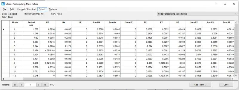
Modal Participation Ratio Check
Go to model explorer> Tables> Analysis Result> Structure Output> Model Information> Modal Participation Mass ratio
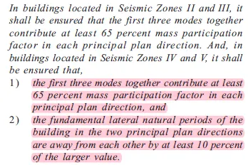
As per IS 1893:2016 clause 7.1
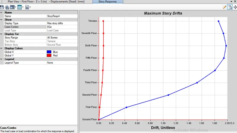
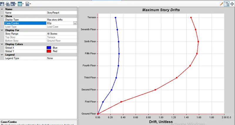
Check for the Inter-Story Drift
Go to Display> Story Response Plots
Select maximum story drifts
Check for EQx and EQy
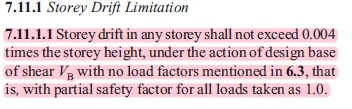
According to IS 1896:2016,
Story Drift in the X-direction
Story Drift in the Y-direction
Check the lateral load % taken by shear walls
The shear wall should take at least 80% of the lateral load
Go to Display> Force / Stress diagrams> Support Spring Reactions
Check the reactions at base due to lateral loads in X any Y directions (EQx and EQy)
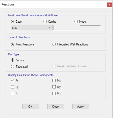
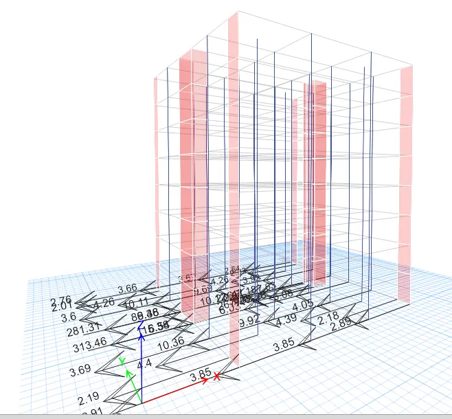
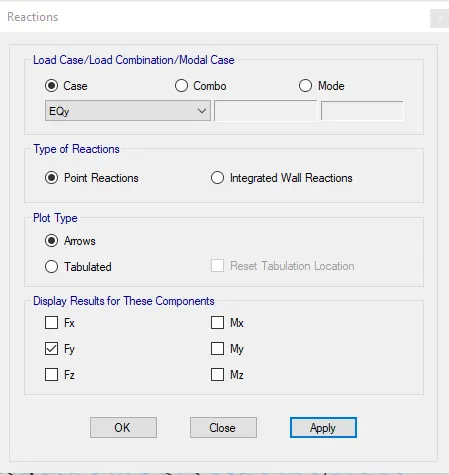
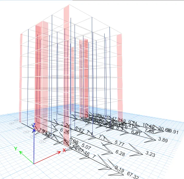
Calculate the total base reaction taken by the shear walls and divide by the total base shear of the building, and if the percentage is ≥80% then there is no need to provide more shear walls.
The base shear taken by the shear walls in each direction is more than 90%. Hence the length of shear walls is sufficient.
Check for axial load ratio
As per IS 13920
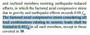
Therefore the maximum axial load should be
0.4 fck c.s.a. oo column
0.4 x 400 x 600 x 30 /1000 =2880kN
Checking each column in all frames for this maximum load
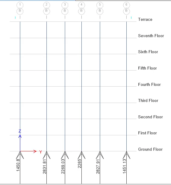
The maximum load is 2831kN at B2.
Hence OK.
RESULT
The structural modal of the G+7 building has been developed that complies with IS 1896 and IS 13920. After framing the layout, the Response Spectrum analysis has been carried out. Necessary checks have been carried out and also verified the values with the code.