Structural dynamics
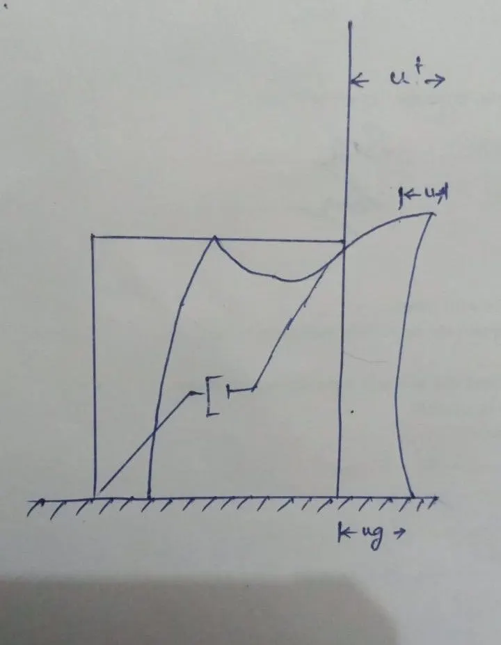
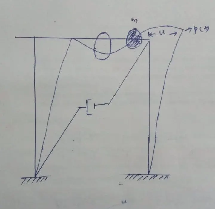
1. Differentiate Static analysis and Dynamic analysis with proper representing pictures
INTRODUCTION:
Structural dynamics is a type of structural analysis which covers the behavior of a structure subjected to dynamic (actions having high acceleration) loading. Dynamic loads include people, wind, waves, traffic, earthquakes, and blasts. Any structure can be subjected to dynamic loading.
AIM:
To Differentiate Static analysis and Dynamic analysis
PROCEDURE:
| STATIC ANALYSIS | DYNAMIC ANALYSIS |
| 1. Load is not variable with time and neglected due to slow applying of load. | 1. Load is variable with time due to fast applying of load and vibration. |
| 2. Motion of the structure can be disregarded. | 2. Motion can not be disregarded (can't be considered as static). |
| 3. There is no necessity to count Inertia and damping forces in case of static analysis, but the elastic force should be accounted. | 3. Inertia and damping forces should be accounted for the calculation of dynamic analysis. |
| 4. There is no inertia effect on static analysis. | 4. Inertia effect is considered in dynamic analysis. |
| 5.It doesn’t matter how you apply the load. Solver assumes that this is happening extremely slowly. This means that the way you apply the load has no impact on structural behavior. | 5.Dynamic analysis is the process of testing and evaluating a program - while software is running. |
|
6.Structural response to the static load CAN differ in time (you know, things like creep, relaxation, etc.). Engineers usually view such analysis as more specialistic, and not “simple static”. Still, structural response changing in time is an option in static design. |
6.The number of independent dispalcements required to define the displaced positions of all the massive relative to their original position is called the number of Degrees of Freedom (DOFs) for dynamic analysis. |
|
7.The load is not changing in time – it is just there… and that’s that! |
7.A single degree of freedom system subjected to externally applied static force with no dynamic excitation. |
Static analysis
RESULT:
Finally we differntiate the static analysis and dynamic analysis
2. Explain the following with relevant force-displacement graph
- Elastic behavior
- Inelastic behavior
- Plastic behavior
- Non-linear Inelastic behavior
AIM:
To explain the elastic , inelastic, plastic and non linear behaviour
PROCEDURE:
1.ELASTIC BEHAVIOR:
- Elasticity is the ability of a body to resist any permanent change to it when stress is applied. When stress application ceases, the body regains its original shape and size. Different materials show different elastic behaviour. The study of the elastic behaviour of a material is of much importance.
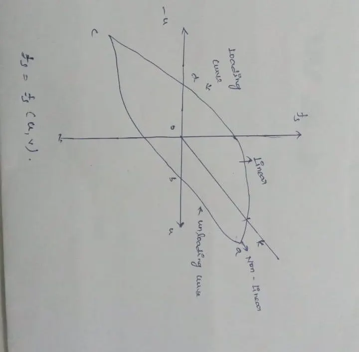
- Elastic behavior is the property of the material upto which the material can retain it's shape. From the aforementioned graph it is clearly mentioned that upto a certain point from "O" the graph is linear and shown its elastic properties.
- For a linear system the relationship between the lateral force fs and the resulting deformation u is linear, i.e.,
fs = ku
where k is the lateral stiffness of the system, its units are force/length.
2.INELASTIC BEHAVIOR:
- Deformation of a material that does not disappear on removal of the force that produced it.
- Force displacement relationship becomes non-linear and inelastic at large deformations.
- Force fs corresponding to deformation is not single valued and depends on history of deformations and whether deformations is increasing or decreasing.
- Thus the resisting force can be expressed as
- fs = fs(u,v)
- Where the constant c is the viscous damping coefficient, it has units of force x time/length.
- Inelastic behavior is the property of the material when the material can't retain it's previous shape after a certain deformation. In the aforementioned graph inelastic behavior has been shown in the upper shape of the curve upto point "a".
3.PLASTIC BEHAVIOR:
- For stresses beyond the elastic limit, a material exhibits plastic behavior. This means the material deforms irreversibly and does not return to its original shape and size, even when the load is removed. When stress is gradually increased beyond the elastic limit, the material undergoes plastic deformation.
- Plastic behavior occurs when the material completely lost it's ductility. In the aforementioned graph plastic behavior occurs during unloading after point "a".
4. NON LINEAR INELASTIC BEHAVIOR:
- Materials have elastic behaviour usually only up to a certain load, which is called the 'yield point'. After that, the deformations are plastic. Rubber, for instance, has an elastic stress–strain curve, but the relation is not linear − in such cases nonlinear elastic models are required.
- Non-linear inelastic behavior occurs after the line from "O" tends to bend towards point"a".
RESULT:
Finally we explain the all of the above
3. Explain Mass, Stiffness & Damping components in the equation of motion
AIM:
To explain Mass, Stiffness & Damping components in the equation of motion
PROCEDURE:
1.Mass:
- Structural analysis is the prediction of the response of structures to specified arbitrary external loads. During the preliminary structural design stage, a structure's potential external load is estimated, and the size of the structure's interconnected members are determined based on the estimated loads.
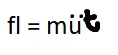
- The roof mass without the stiffness or damping of the frame. The external force fi on the mass component is related to the acceleration by fi=m(u^double dot).
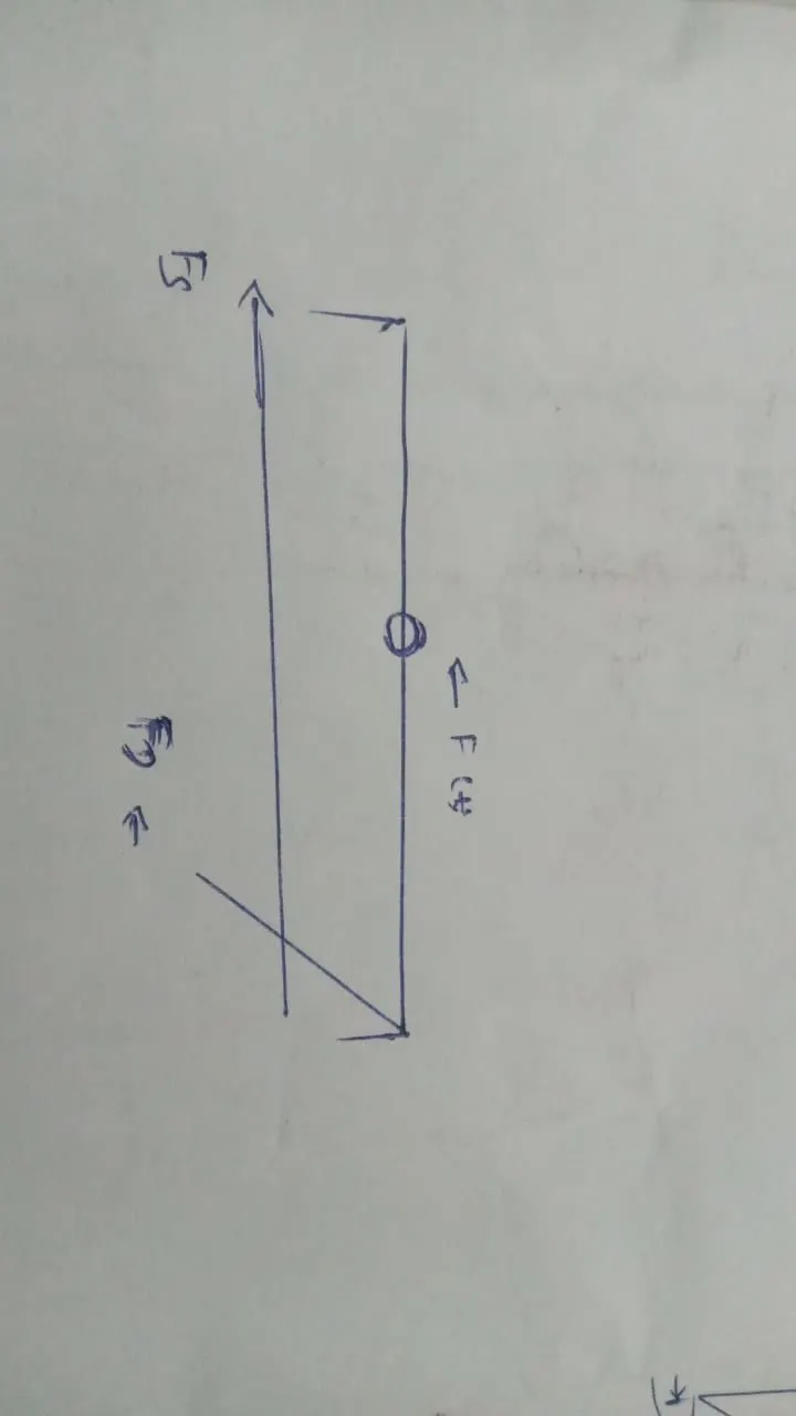
- The Single degree of freedom system can be viewed as a combination of three pure, independent systems.
- The stiffness component: Frame without damping or mass. The external force fs on the stiness component is related to displacement u by fs = ku, if the system is linearly elastic.
- The damping component: Frame with its damping property but no stiffness or mass.
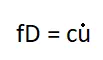
- The external force on the damping component is related to velocity by fd = cv.
- The mass component: The roof mass without the stiffness or damping of the frame. The external force fi on the mass component is related to the accleration by
-

-

- The displacement of the ground is denoted by ug, the total (or absolute) displacement of the mass by uT, and the relative displacement between the mass and ground by u.
- At each instant of time these displacements are related by:
- uT(t) = u(t) + ug(t)
- From the free body diagram including the inertia force fi, the euation of dynamic equilibrium is :
- fl + fD + fs = o
- Thus for a linear elastic system, the inertia force fl is related to the acceleration u of the mass by:
-
- Thus, the euation of motion governing the relative displacement or deformation u(t) of the linear structure subjected to the ground accleration ug(t):
-
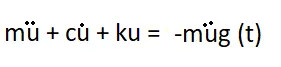
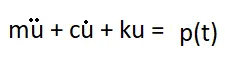
- Comparision of two equations shows that the equations of motion for the structure subjected to two separate excitations - ground accleration ug(t) and external force = -mug(t) are one and the same.
-
-
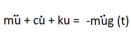
- Thus the relative displacement or deformaation u(t) of the structure due to the ground accleration ug(t) will be identiical to the displacement u(t) of the structure if its base were stationary and if it were subjected to an external force = -mug(t).
Stiffness Component:
The frame is without damping or mass. The external force fs on the stiffness component is related to displacement u by fs= Ku, if the system is linearly elastic.
Damping Forces:
- Its impact is evident from the steady decline in amplitude of a vibrating body.
- Sources of damping in vibrating structures
- Friction at steel connections
- Opening and closing of microcracks in concrete.
- Friction between the structural and non structural elements such as partition walls.
- Damping in structure is represented in an idealized manner called equivalent viscous damping.
- The damping forces fd is related to the velocity across the linear viscous damper by
-
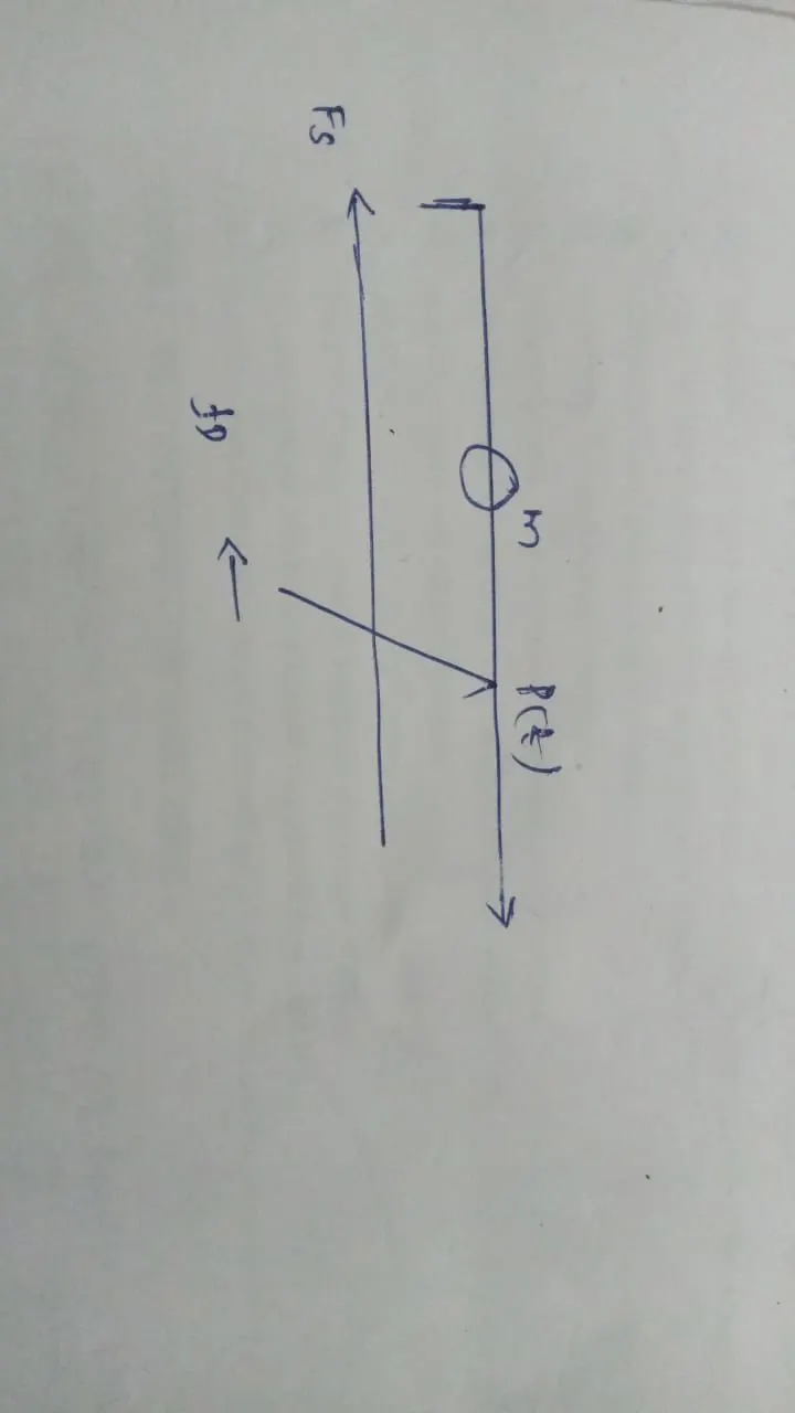
- The differential equation governing the displacement u(t) of an idealized single story frame subjected to an externally applied force p(t) can be derived using Newton's second Law of the Motion.
-

RESULT:
Finally we give the explanation about mass , stiffness and damping
4. Provide relationship between Natural period (Tn) & Natural frequency (f) and provide their definitions
AIM:
To gives an relationship between Natural period and Natural frequency
PROCEDURE:
NATURAL PERIOD:
- The natural period of a building is simply a time taken by it to undergo one complete cycle of oscillation. The natural period is one of the properties or building which is controlled by mass and stiffness.
- Natural period of vibration of the system (Tn) is the time required for the undamped system to complete one cycle of free vibration (Unit is seconds).
- It is related to the natural circular frequency of vibration, ωn, in units of radians per second
- Tn = 2π/ωn or ωn = 2π/Tn
NATURAL FREQUENCY:
Natural frequency (f) =√stiffness/√Mass of structure.
- Natural Frequency: All physical structures have natural frequencies. These are the frequencies at which the structure will tend to vibrate when subjected to certain external forces. These frequencies are dependent on the way mass and stiffness are distributed within the structure.
- Take the case of a very tall building which is susceptible to damage whan earthquake occur will have higher group and hence lower natural frequency.
- Thereby, it is desirable to have higher natural frequencies. Also, at low natural frequencies, the structure can resonate easier and hence lead to amplification.
- I do not know enough about building dynamics to comment about this mathematically, but this is a plausible argument.
-
- The number of cycles (or one complete revolution) executed by system in one second (unit is hertz)
fn =(1/Tn)
Therefore, the relation between natural period of vibration of the system(Tn) and natural frequency(fnfn)
is fn=(1/Tn)
RESULT:
Finally we explain relationship between Natural period and Natural frequency
5.Explain in detail about Response spectrum & its Graph
AIM:
To explain in detail about response spectrum
PROCEDURE:
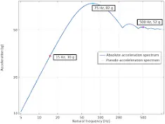
- Response spectrum analysis is a method to estimate the structural response to short, nondeterministic, transient dynamic events. Examples of such events are earthquakes and shocks. Since the exact time history of the load is not known, it is difficult to perform a time-dependent analysis
- A central concept in earthquake engineering, response spectrum is a practical means of characterizing ground motions and their effects on structures of different Tn.
- It provides a convenient means to summarize the peak response of all possible linear Single degree of freedom systems to a particular component of ground motion.
- It also provides a practical approach to apply the knowledge of structural dynamics to the design of structures and to the development of lateral force requirements in building codes.
- A plot of the peak value of a response quantity (u,v and a) as a function of the natural vibration period Tn of the system, is called Response spectrum for that quantity.
- Each such plot is for Single Degree of Freedom systems having a fixed damping ratio and several such plots for different values of damping ratio are included to cover the range of damping values encountered in actual structures.
- The response spectrum can be of 3 typess.
- The deformation response spectrum is a plot of peak u, against Tn for fixed damping ratio.
- A similar plot for peak velocity is the relative velocity of response spectrum, and for peak uT is the accleration response spectrum.
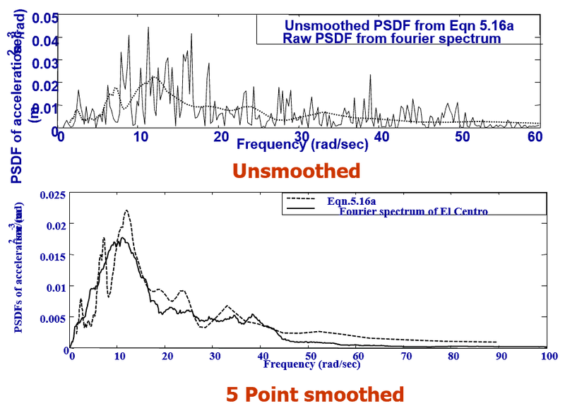
- I give some examples as like
RESULT:
Finally we have explain response spectrum