Creating a Floor plan, Footing detail and Isometric view using AutoCad
Floor Plan
Introduction:
In architecture and building engineering, a floor plan is a technical drawing to scale, showing a view from above, of the relationships between rooms, spaces, traffic patterns, and other physical features at one level of a structure
Aim:
They provide a way to visualize how people will move through the space. Floor plans makes it easier to check if the space is suitable for its intended purpose, work through any potential challenges and redesign before moving forward into more elaborate planning or building stages.
Procedure:
i.) step 1 we draw a outer layout for an 35x33 feet area
ii.) I took carried out at the area of 1155 sq.ft
iii.) we set unit for architectural drawing unit
iv.) start at the @1,1 systematic point and choose rectangle to draw an layout start 35,33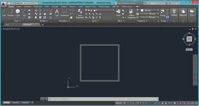
vi.) Next step we do an partion wall to seprate the layout
vii.) To seperate the room are im taking car parking and service room and go down
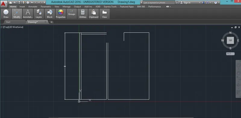
viii.) Once draw the layout i will checked the dimension as per the drawing
ix.) once partion wall the door will mentioned and partioned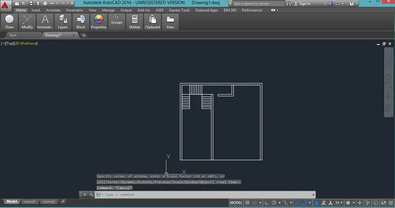
x.) next will start on to the staircase on the intermediate at the lift pit
xi.) In the lift have an size of 4.6ftx5.6ft
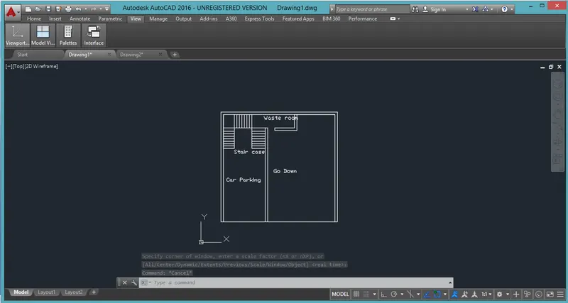
xii.) After completing the lift pit we stared at the text over the layout
xiii.) wementioned the room are car parking, staircae, go down and waste room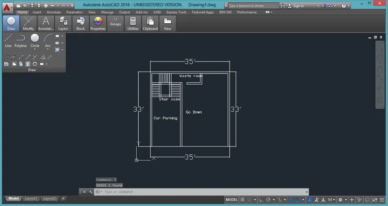
xiv.) Once the comppleted the drawing check their dimension
xv.) concluion draw the ground floor plan
Result:
Using autocad we draw the floor plan
FOOTING DETAIL
Introduction:
Basically while construction of any building or structure we need find bearing capacity of that soil mass so that it can safely bear the loads coming to the structure in future.
Aim:
Foundation plan will be prepared by two ways either taking all the necessary test on soil mass to calculate it's bearing capacity or by observing nearby construction (this happen mostly in rural areas) and foundation that used for construction.
Procedure:
i.) First we set a unit for layout unit is an architectural limits
ii.) Starting tarting @1,1 at the point we draw a rectangle a size 35x33 feet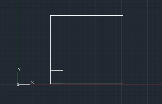
iii.) We draw the column for the footing purpose
iv.) Marked the outer line for the footing size
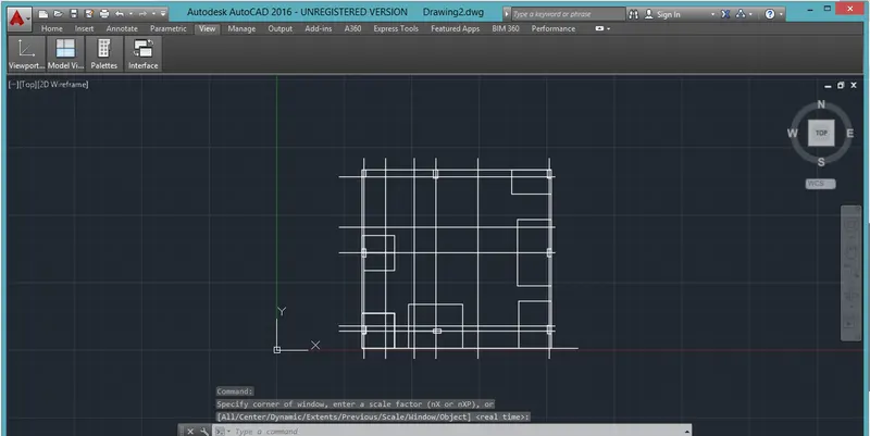
v.) Some of the column Cf1 column are the not large amount of the footing
vi.) The column size are the 1'6" and width have 9" coomon for all of this
vii.) the footing size are nominally 6 ft to arrount 10 ft
viii.) simantenously we check the dimension for the layout
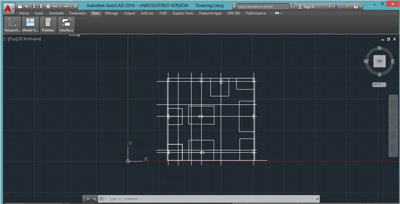
ix.) Once we completed the footing level we take an dimenion for an column and footing
x.) Finally 10 columns are draw and marked the meaurements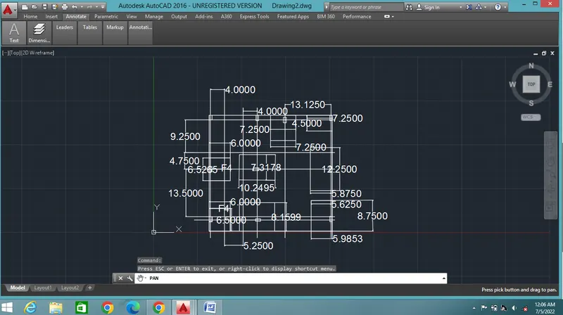
Result:
Using of autocad for drawing footing detail
ISOMETRIC VIEW
Introduction:
The definition of an isometric drawing is a drawing of a three-dimensional shape on a two-dimensional surface along a vertical line with at least two identified points. All the horizontal lines of the image are created from the predetermined vertical line at 30-degree angles. The angles play a huge part in creating the three-dimensional, isometric view.
Aim:
Drawing a three-dimensional shape on a flat two-dimensional surface can be difficult. Trying to make sure the shape does not look distorted in any way takes some practice. Artists use various methods that create the illusion of a three-dimensional shape on a flat surface, such as shading, perspective, and shadowing. Although an artist can strategically make an image appear to be lifelike, the image may not be drawn to scale. Engineers, architects, and those in other technical careers face the huge challenge of creating three-dimensional shapes on a flat surface. Their drawings are intended to represent real-life buildings or structures, and putting them onto a two-dimensional surface is a task. The use of isometric drawing is beneficial and comes in handy for those working in these careers.
Procedure:
i.) First we set an units at architectural drawing
ii.) choose isometric view use F5
iii.) Draw at the isometric right 5 unit at square
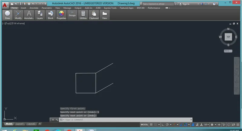
iv.) Next we go to an the isometric top 5 unit for both side
v.) Next isometric top right 3 unit and down at the 11 unit
vi.) Top at the 5 unit will connect
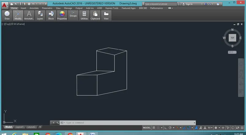
Result:
Draw an isometric view drawing uing autocad.