Structural analysis of a buidling using Robot Structural Analysis
Question:1) What are HVAC systems? Why are they essential in the modeling of buildings
Answer) Heating ventilation and Airconditioning is the word coined to describe the flow and circulation of air inside the building. Other than natural ventilation artifical venatilation is more useful to provide good controlled hot and cold air condition for the inhibitants.
The system consists of vents and air handling units which takes hot air from the building and cools it It emits the hot air to outside.
Question:2) From week 7 assignment, based on the building designed use the same Revit file to design a HVAC system for each floor to cover the topics included in the class.
a. Typical HVAC unit includes Distribution center
b. Collector
c. Ducts
d. Blower
Based on the layout choose appropriate ducts and elevation using property browser and assign the components to appropriate groups to complete modeling of the HVAC unit
Step 1:) Insert architetcure link > into mechanical template
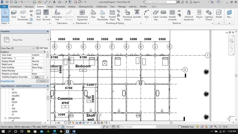
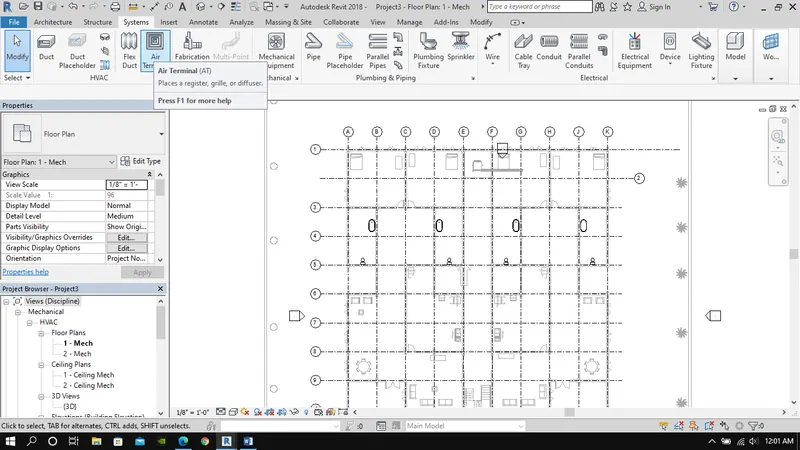
Step 2:) Systems > Air terminals
Step 3:) Place on the room ceiling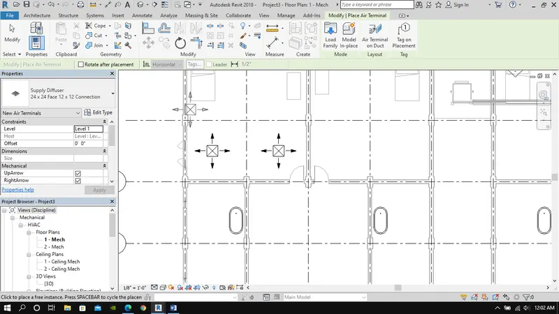
Step 4:) System > Mechanical equipment
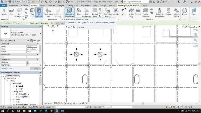
Step 5:)Air handling units
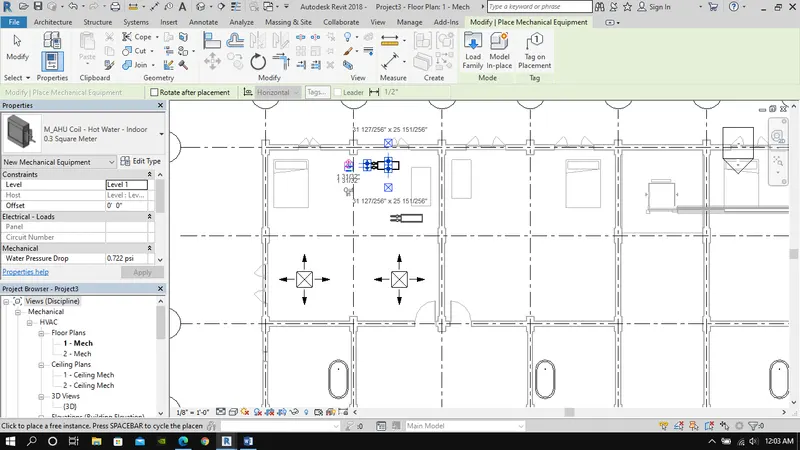
Step 6:)Click all three > Duct > "Select the unit" > Generate layout
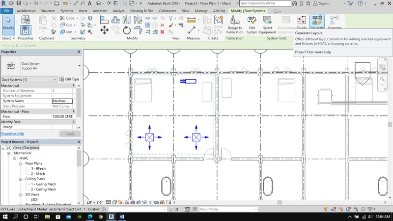
Step 7:)Select the suitable layout > finish
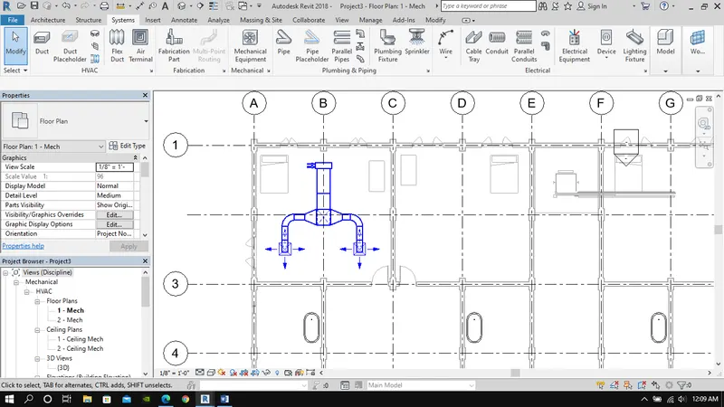
Resul: HVAC unit was placed
Question:3) Use the add-ins tab to load plug-ins for robot structural analysis to your Revit software
Step 1:) Click shopping cart icon in revit window >Go to autodesk website
Step 2:) Search the structural analysis tool kit > Robot structural analysis (based on revit version > download & install
Step:3) Check > Go to revit > Analyse > robot structural analysis
Question:4) Why do we need to assess buildings/analyze while modeling elements? Does design affect modeling in anyways?
Answer: Budiling are analysed using design codes to verify whether the building meets the requirements needed for the concernd purpose of the bulding. Various loads external & internal are applied on the building to analyze the elements for internal stresses in the each element which contribute to the strength and servicieability of the building.
Analysis usually check the material and geometrical changes in building components. Performance checks is helpful in determining the most suitable model for the building.
Question:5) From the structural model developed in week 6 and 7, export the complete analytical model to robot structural analysis.
For residential RCC building IS 456-2000 is used & IS 875 for Dead load, Live load, Windload and IS 1893 for earthquake loading
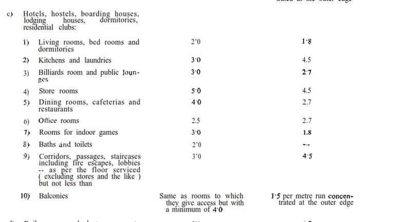
For live load
For wind load & earthquake at bangalore location
Design for earthquake load done in accordance with IS 1893:2016
- Location = Bangalore
- Site zone = II (Fig 1, Page 11 of IS 1893:2016)
- Zone factor, Z = 0.1 (Table 3, Clause 6.4.2 of IS 1893:2016)
- Importance factor, I = 1(Table 8, Clause 7.2.3 of IS 1893: 2016)
- Response reduction , R = 3(Table 9, Clause 7.2.6 of IS 1893: 2016)
Design for wind load done in accordance with IS 875 2015 Part 3
- Location = Bangalore
- Wind speed ,Vb = 33 m/sec (Annex A, Clause 6.2 of IS 875:2015 Part 3)
- Site Zone = Category 2 (Table 2, Clause 6.3.2.1 of IS 875: 2015 Part 3)
- K1 = 1 Risk Coefficient for general building (Table 1, Clause 6.3.1 of IS 875: 2015 Part 3)
- K2 for Terrain 2 ( Table 2, Clause 6.3.2.2 of IS 875: 2015 Part 3)
- K3 = 1 Topography factor for slope of less than 3 (Clause 6.3.3 of IS 875: 2015 Part 3)
- K4 = 1 Importance factor (Clause 6.3.4 of IS 875: 2015 Part 3)
Design wind speed, Vz = Vb×K1×K2×K3×K4 =33 m/sec (up to 10 m height)
- Ka = 1 Area averaging factor (Table 4, Clause 7.2.2 1 of IS 875: 2015 Part 3)
- Kc = 0.9 (Clause 7.3.3.13 of IS 875: 2015 Part 3)
- Kd = 0.9 Wind directionality factor (Clause 7.2.1 of IS 875: 2015 Part 3)
Wind pressure at any height, Pz = 0.6 × Vz2 = 0.65 KN/m2
Design wind pressure, Pd = Pz × Ka × Kc × Kd = 0.53 KN/m2
a. List your assumptions on what boundary conditions will be realistic for the analysis approach
Answer: Fixed support for all columns since it is RCC foundation and column
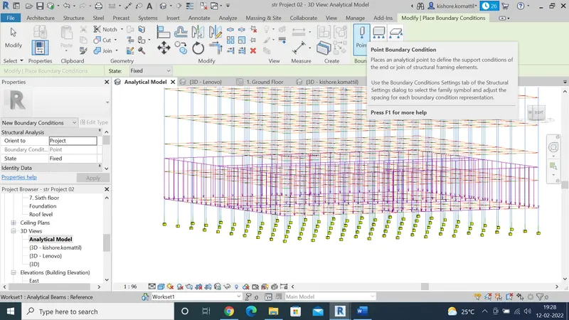 b. Use the design standards to decide what loads must be applied to floorings based on the type of structure decided
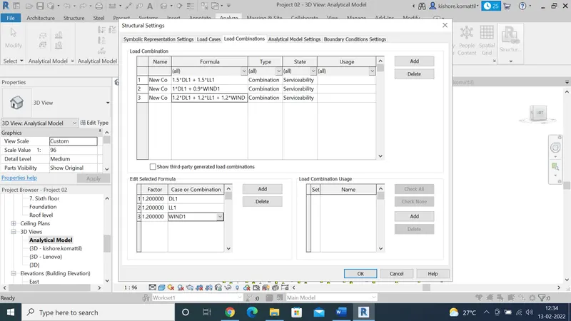
c. List the load combinations and include them in the analysis model
d. Analyze the building and report the following results
i. Maximum Moment in each floor for all Load Combinations
ii. Maximum Displacement in each floor for all Load combinations
iii. Lateral Displacement in building for all Lateral Load combinations
Step:1) Export model to robot structural analysis
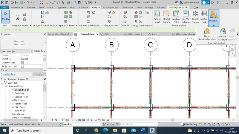
Step:2) Export model to robot structural analysis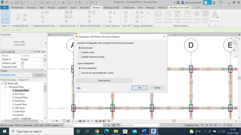
Step:3) Edit >Select all > Load definitions
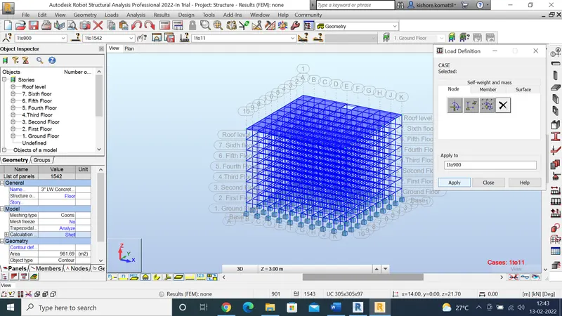
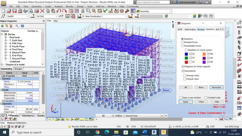
Step:4) Analyse > Calculation (for result)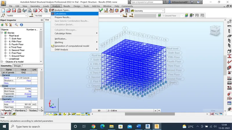
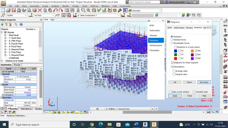
Step:5) Bending moment
Step:6) Force in Z direction
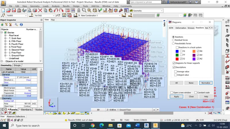
Step:7) Force in X & Y direction
Question:6) What is energy analysis and why do we need to consider it while modeling in Revit?
How does the factor of sustainability improve the quality of your design?
Answer: Energy analysis is used to asses heat dissipated from the building structure or components depending on their physcal and chemical properties.
It checks the heat loss and gain from a particular process or material and helps in controlling cost.
A sustainable or zero efficent building utlizes less use of natural resources thus reducing carbon emission. Price of such buildings will be less than a normal RCC or steel bulding.
Buildings demand energy in their life cycle right from its construction to demolition. Studies on the total energy use during the life cycle are desirable to identify phases of largest energy use and to develop strategies for its reduction.
Building's life cycle energy demand can be reduced by reducing its operating energy significantly through use of passive and active technologies even if it leads to a slight increase in embodied energy. However, an excessive use of passive and active features in a building may be counterproductive. It is observed that low energy buildings perform better than self-sufficient (zero operating energy) buildings in the life cycle context
e. After analysis, do you think you have a better approach or idea in modeling structural members?