Structural analysis of a buidling using Robot Structural Analysis
1) What are HVAC systems? Why are they essential in the modeling of buildings
HVAC SYSTEM IS ONE OF THE IMPORTANT COMPONENT IN BUILDING MODELLING.
HVAC STANDS FOR HEATING , VENTILATION , AND AIR CONDITIONING .
HEATING MEANS TO INCREASE THE TEMPERATURE OF THE INPUT AIR WHICH FLOWS INTO THE BUILDING.
VENTILATION IS REPLACEMENT OF OLD AIR PRESENT IN THE BUILDING.
AIR CONDITIONING IS TO COOL THE AIR ENTERING THE BUILDING.
HVAC ARE IMPORTANT TO INCREASE THE SUSTAINABILITY AND CONDITIONING OF THE BUILDING.
IT IMPROVES COMFORT AND HELPS TO INCREASE THE EFFICIENCY OF THE WORKERS IN THE BUILDING.
HVAC REFERS TO THE DIFFERENT SYSTEMS USED FOR MOVING AIR BETWEEN INDOOR AND OUTDOOR AREAS , ALONG WITH HEATING AND COOLING BOTH RESIDENTIAL AND COMMERCIAL BUILDINGS.
THEY ARE THE SYSTEMS THAT KEEP YOU WARM AND COZY IN THE WINTER AND FEELING COOL AND FRESH IN THE SUMMER.
THEY ALSO ARE THE SYSTEM THAT FILTER AND CLEAM INDOOR AIR TO KEEP YOU HEALTHY AND MAINTAIN HUMIDITY LEVEL AT OPTIMAL COMFORT LEVELS.
EACH COMPONENT IN YOUR HOME MAY BE SEPARATE , SUCH AS A RADIANT SYSTEM COMBINED SYSTEM SUCH AS CENTRAL HEATING AND AC SYSTEM THAT USE A SINGLE BLOWER TO CIRCULATE AIR VIA INTERAL DUCTS IN A HOME , OR WITH A DUCTLESS SYSTEM FOR DIFFERENT ROOMS OR ZONES IN HOUSE.
THE PURPOSE OF AN HVAC SYSTEM IS MORE THAN JUST WARMING OR COOLING A SPACE.
INSTEAD IT SERVES TO IMPROVE INDOOR AIR QUALITY AND PROVIDE COMFORT FOR EVERYONE INSIDE A BUILDING.
WHILE THERE ARE SEVERAL DIFFERENT TYPES OF HVAC SYSTEM , THEY ALL BEGIN WITH THE SAME ESSENTIALS.
FIRST , THERE IS A SOURCE OF FRESH AIR INTAKE FROM THE OUTSIDE OR FROM WITH IN THE HOME.
THIS PROCESS IS CALLED VENTILATION , AND IT HAPPENS IN TWO DIFFERENT WAYS.
NATURAL VENTILATION IS PRESENT IN MOST HOMES AND REFERS TO THE WAY AIT TYPICALLY MOVES IN AND OUT THROUGH WINDOW , DOORS , VENTS , AND OTUER OPENING.
THIS EXCHANGE OF AIR IS NECESSARY TO REPLENISH OXYGEN , AND TO REMOVE ODORS , CARBON DIOXIDE AND EXCESSIVE MOISTURE.
MECHANICAL VENTILATION USE A MECHANICAL SYSTEM - THE V IN HVAC TO MOVE AIR IN AND OUT.
IN THE PAST , THERE WAS PLENTY OF NATURAL VENTILATION IN MOST HOMES FROM GAPS AND CRACKS IN THE CONSTRUCTION ALONG WITH OPENING AND CLOSING OF DOORS.
HOWEVER , MODERN CONSTRUCTION IS CREATING HOMES THAT ARE FER MORE TIGHTLY SEALED SO VENTION IS BECOMING AN INCREASINGLY IMPORTANT COMPONENT IN HOME HVAC SYSTEMS.
ONCE THE AIR IS BROUGHT IN IT IS DRAWN INTO AN AIR HANDLING UNIT WHERE THE WORK BEGINS.
HERE , THE AIR IS BROUGHT IN , IT IS DRAWN INTO AN AIR HANDLING UNIT WHERE THE WORK BEGINS.
HERE , THE AIR IS DRAWN THROUH FILTERS TO REMOVE DIRT , DUST , ALLERGENS , AND OTHER PARTICLES.
NEXT UP , IS COMFORT AIR IS EITHER SENT TO BE HEATED OR SENT TO BE COOLED AND HAVE EXCESS HUMIDITY REMOVED.
ONCE THE AIR IS CEAN , FRESH , AND AT A COMFORTABLE TEMPERATURE , IT IS DIRECTED INTO HOME.
FOR CENTRAL SYSTENS , THIS MEANS MOVING THROUGH A NETWOTK OF DUCTS AND REGISTERS TO DIFFERENT ROOMS.
FOR OTHER SYSTEMS , THIS USUALLY MEANS BEING DIRECTED RIGHT INTO THE SPACE.
2) From week 7 assignment, based on the building designed use the same Revit file to design a HVAC system for each floor to cover the topics included in the class.
a. Typical HVAC unit includes Distribution center
b. Collector
c. Ducts
d. Blower
Based on the layout choose appropriate ducts and elevation using property browser and assign the components to appropriate groups to complete modeling of the HVAC unit
AIM : TO CREATE AN HVAC SYSTEM FOR PROJECT 2
PROCEDURE :
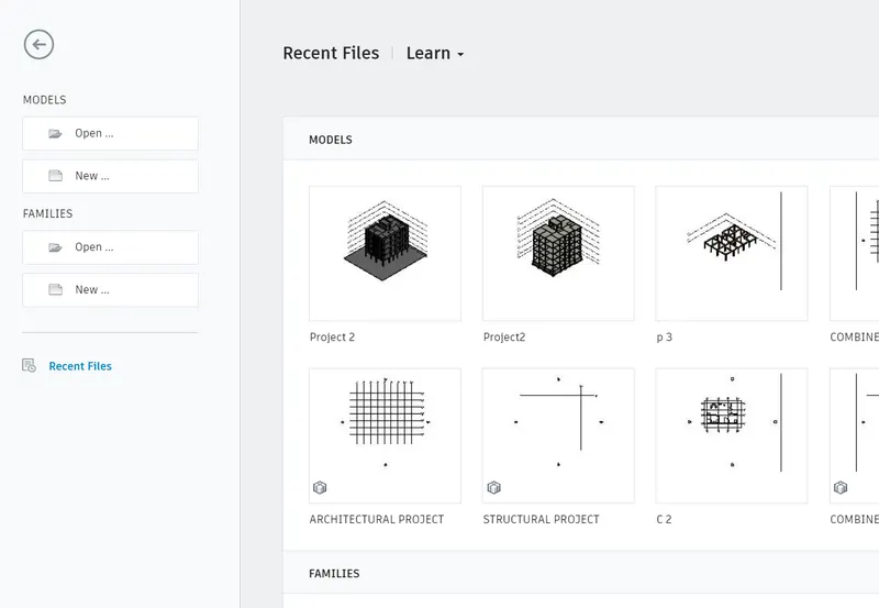
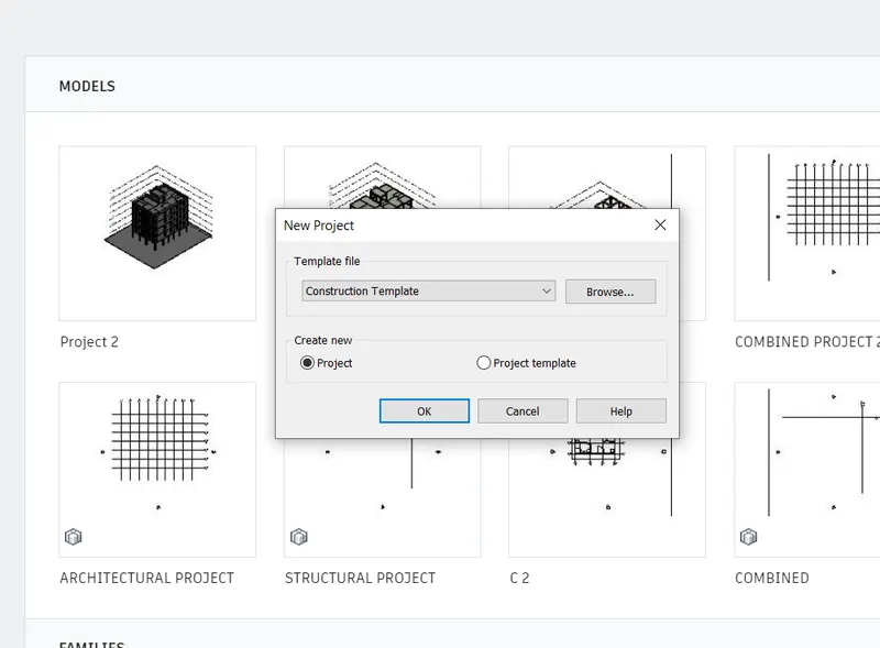
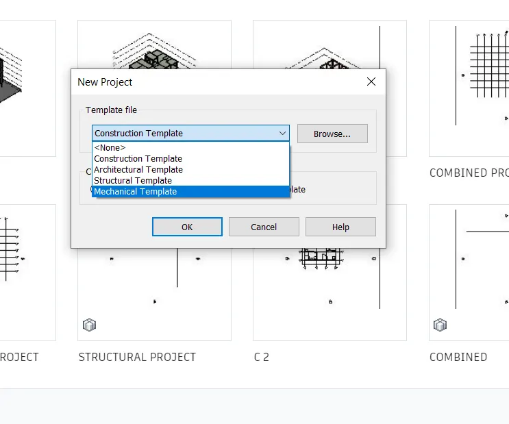
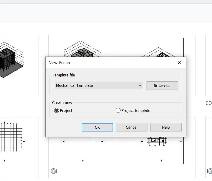
STEP 1 : TO OPEN THE NEW SYSTEM TEMPLATE FILE
GO TO REVIT ICON DOBLE CLICK ON IT
GO TO CLICK ON NEW
TO CHANGE THE REQUIRED TEMPLATE
CLICK ON OK
STEP 2 : TO LINK THE ARCHITECTURAL PROJECT 2
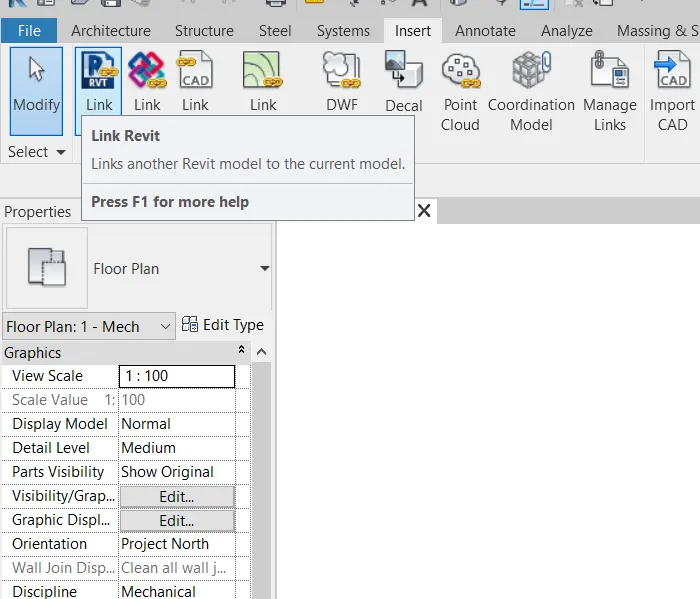
GO TO INSET TAB
CLICK ON THE LINK REVIT OPTION
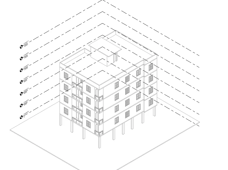
SELECT THE PROJECT 2
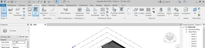
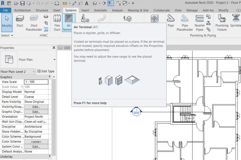
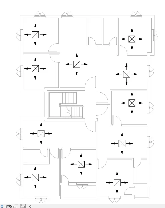
STEP 3 : TO ADDING THE SUPPLY AND RETURN DIFFUSERS
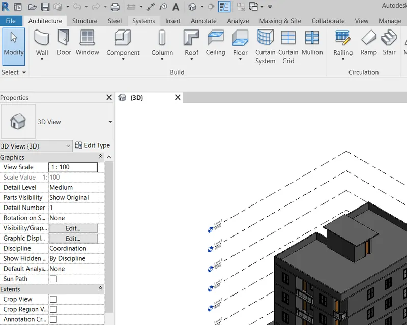
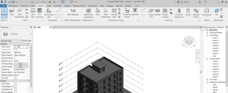
CLICK ON SYSTEM TAB
CLICK ON AIR TERMINAL
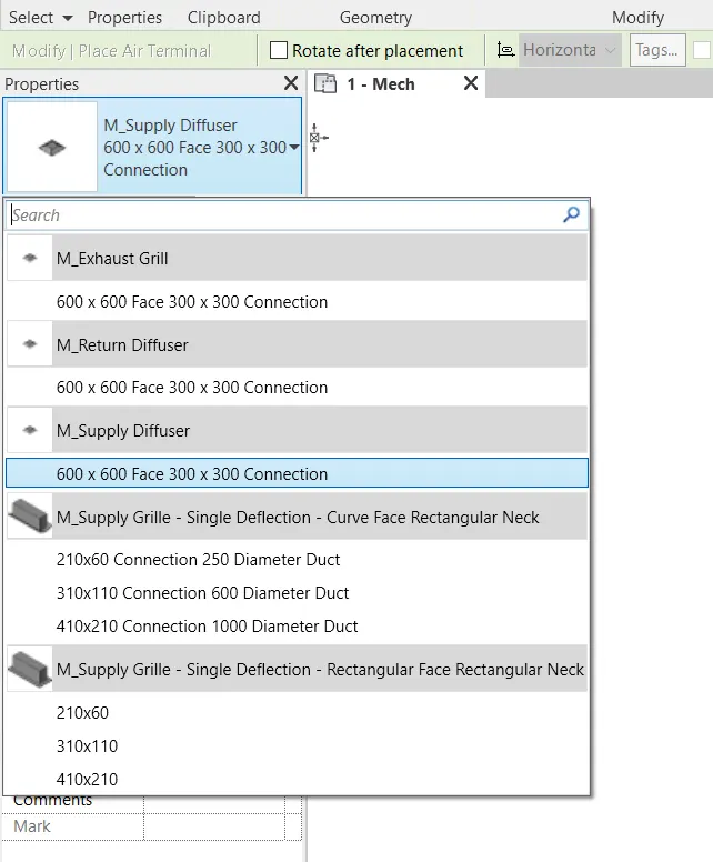
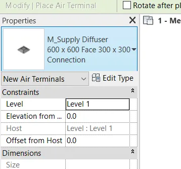
FROM COMPONENTS SELECT SUPPLY DFFUSER
PLACE THE SUPPLY DIFFUSER IN REQUIRED PLACE
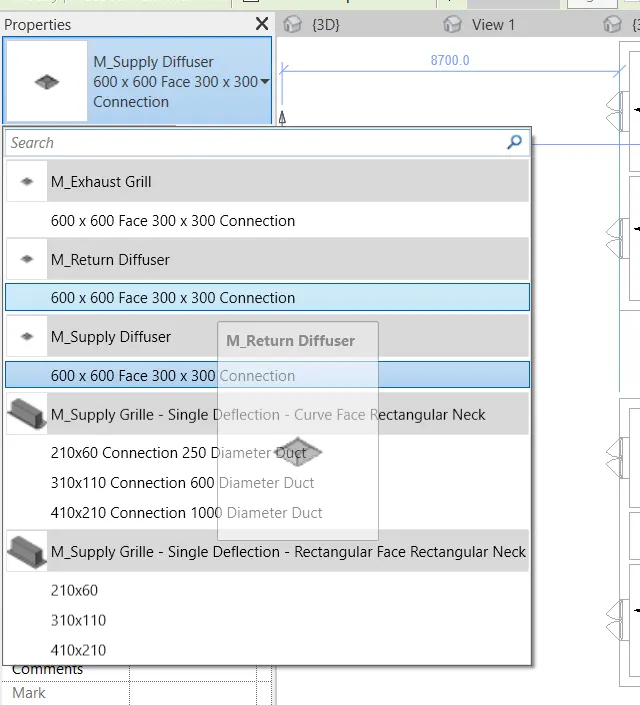
CLICK ON SYSTEM TAB
CLICK ON AIR TERMINAL
FROM COMPONENTS SELECT RETURN DFFUSER
PLACE THE SUPPLY DIFFUSER IN REQUIRED PLACE
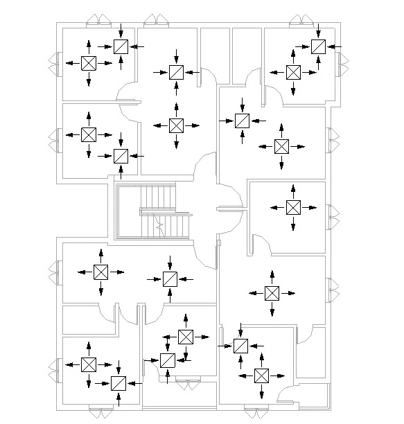
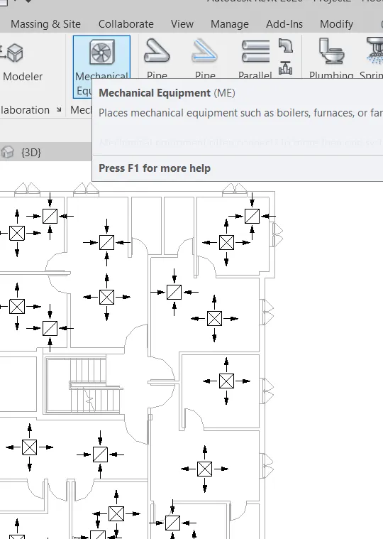
CLICK ON SYSTEM TAB
CLICK ON MECHANICAL EQUIPMENT
FROM COMPONENTS SELECT RETURN DFFUSER
PLACE THE SUPPLY DIFFUSER IN REQUIRED PLACE
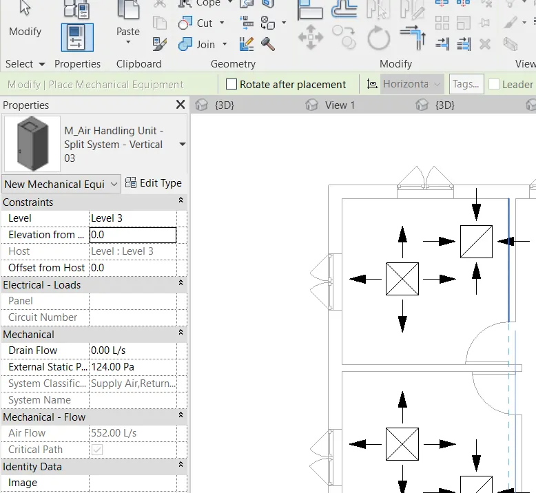
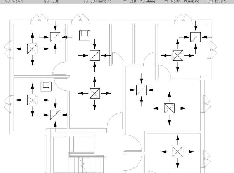
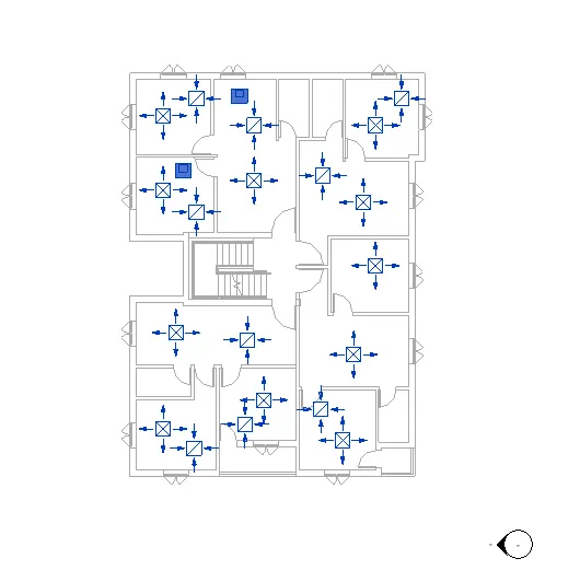
STEP 4 : CREATE THE SYSTEM
SELECT ALL THE SUPPLY DIFFERENT AND AIR HANDLING
CLICK ON DUCTS ON MODIFY TAB
CLICK ON OK
THEN CREATE THE MECHANICAL SUPPLY AIR SELECT LAYOUT AS PER REQUIRED
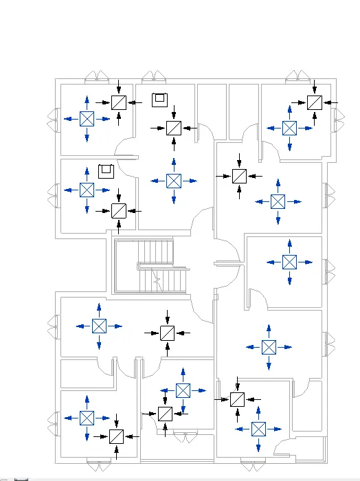
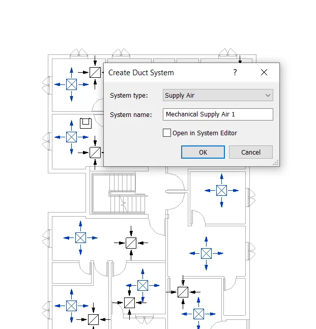
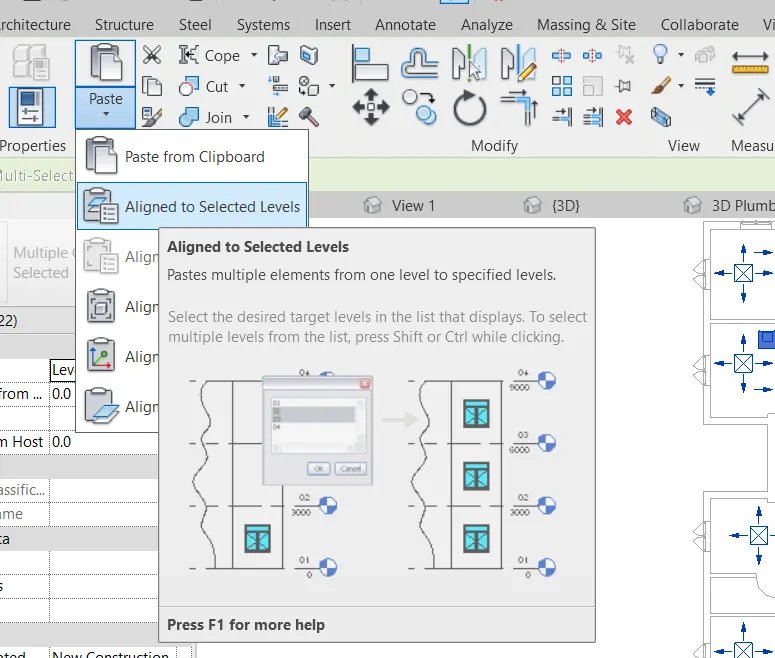
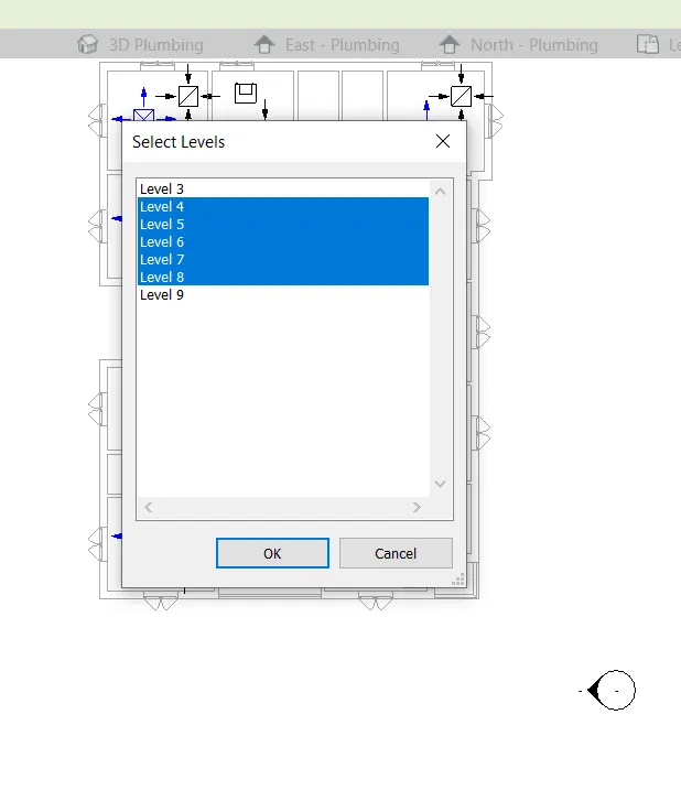
STEP 5 : COPY ON ALL LEVELS
SELECT THE SYSTEM
CLICK ON COPY IN MODIFY TAB
GO TO PASTE DROP DOWN ARROW
THEN SELECT THE REQUIRED LEVELS
CLICK ON OK
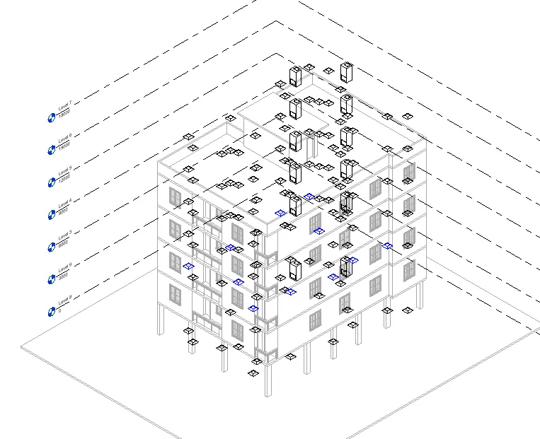
RESULT :
TO SUSFFULY PALE THE HVAC SYSTEM
3) Use the add-ins tab to load plug-ins for robot structural analysis to your Revit software
AIM :
PROCEDURE :
GO TO A NEW TAB IN GOOGLE
CLICK ON AUTODESK WEBSITE
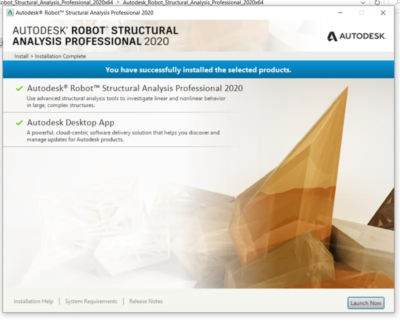
SECRCH THE ROBOT STRUCTURAL ANALYSIS PROFESSIONAL 2020
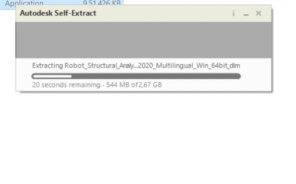
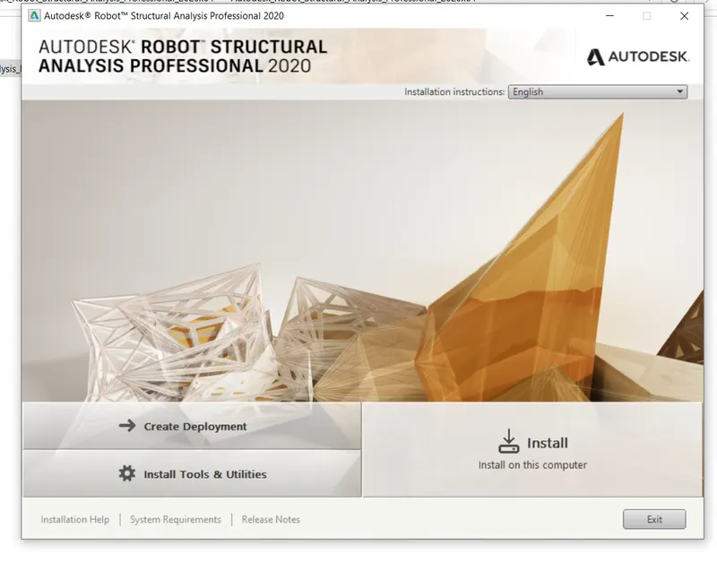
INSTALL THE SETUP FILE DOWNLOAD
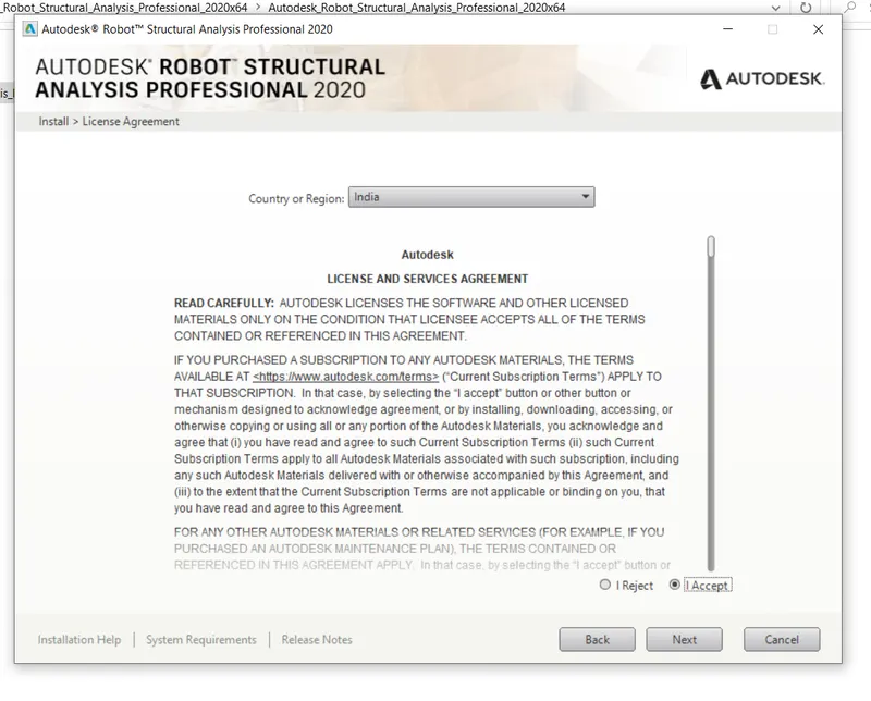
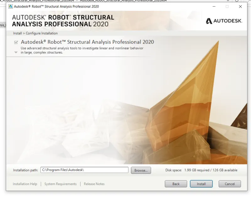
CLICK ON NEXT
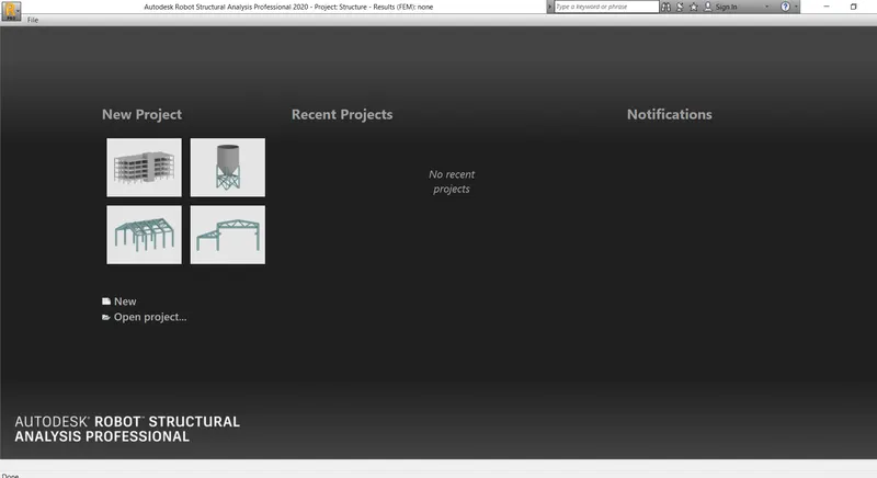
CLICK ON ROBOT STRUCTURAL ANALYSIS
NOW OPEN REVIT PROJECT FILE
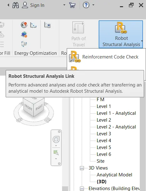
USE THE ANALYZE MENU TO THE ROBOT STRUCTURAL ANALYSIS PROFESSIONAL TO EXPORT THE PROJECT TO THE ROBOT STRUCTURAL ANALYSIS PROFESSIONAL
4) Why do we need to assess buildings/analyze while modeling elements? Does design affect modeling in anyways?
STRUCTURE IS ONE OF THE IMPORTANT COMPONENT OF THE BUILDING.
THE STRUCUTURAL FRAMEWORK IS THE SKELETON TO THE BUILDING.
ALL THE LOADS AND LOAD TRANSFER IS TAKEN CARE BY CREATING THE STRUCTURAL FRAMEWORK.
ANALYZING A BUILDING IS NOTHING BUT CALCULATING FORCES AND BENDING MOMENTS THAT OCCUR WHEN LOADS ARE APPLIED.
REVIT ENABLES US TO CALCULATE THE FORCES , REACTIONS , BENDING MOMENTS ETC BY USING THE ROBOT STRUCTURAL ANALYSIS OPTION MAKING THE WORK OF A DESIGNER EASY.
ENERGY ANALYSIS IS ALSO AN IMPORTANT ASPECT AS IT CALCULATES THE OVERALL PERFORMANCE OF BUILDINGS.
ANALYZING A BUILDING IS VERY IMPORTANT BECAUSE IT GIVES A COMPLETE UNDERSTANDING OF THE BUILDING AND HOW IT ACTS WHEN SOME NATURAL CALAMITIES LIKE TORNADOS , EARTHQUAKES OCCUR.
ANALYSIS OR ASSESSMENT OF BUILDING MAKES US UNDERSTAND HOW MUCH STRENGH A BUILDING GIVES AND HOW MUCH IS THE ACTUAL REQUIREMENT , THIS HELPS US TO MAKE REQUIRE CHANGES TO ATTAIN THE EPECTED FUNCTIONALITY.
STRUCTURAL ANALYSIS IS THE DETERMINATION OF THE EFFECTS OF LOADS ON PHYSICAL STRUCTURES AND THEIR COMPONENTS.
STRUCTURES SUBJECT TO THIS TYPE OF ANALYSIS INCLUDE ALL THAT MUST WITHSTAND LOADS , SUCH AS BUILDING , BRIDGES , AIRCRAFT , AND SHIPS.
THE STRUCTURAL ANALYSIS EMPLOYS THE FIELDS OF APPLIED MECHANICS , MATERIALS SCIENCE , AND APPLIED MATHEMATICS TO COMPUTE A STRUCTURES DEFORMATIONS , INTERNAL FORCES , STRESSES , SUPPORT RECTIONS , ACCELERATIONS , AND STABILITY.
THE RESULTS OF THE ANALYSIS ARE USED TO VERIFY A STRUCTURES FITNESS FOR USE , OFTEN PRECLUDING PHYSICAL TESTS.
STRUCTURAL ANALYSIS IS THUS A KEY PART OF THE ENGINEERING DESIGN OF STRUCTURES.
5) From the structural model developed in week 6 and 7, export the complete analytical model to robot structural analysis.
a. List your assumptions on what boundary conditions will be realistic for the analysis approach
b. Use the design standards to decide what loads must be applied to floorings based on the type of structure decided
c. List the load combinations and include them in the analysis model
d. Analyze the building and report the following results
i. Maximum Moment in each floor for all Load Combinations
ii. Maximum Displacement in each floor for all Load combinations
iii. Lateral Displacement in building for all Lateral Load combinations
e. After analysis, do you think you have a better approach or idea in modeling structural members?
AIM : TO EXPORT THE COMPLETE ANALYTICAL MODEL TO ROBOT STRUCTURAL ANALYSIS SOFTWARE AND DO THE COMPLETE ANALYSIS
PROCEDURE :
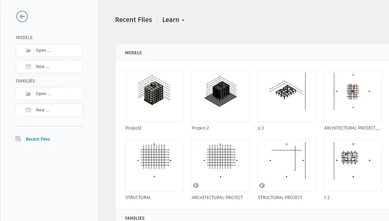
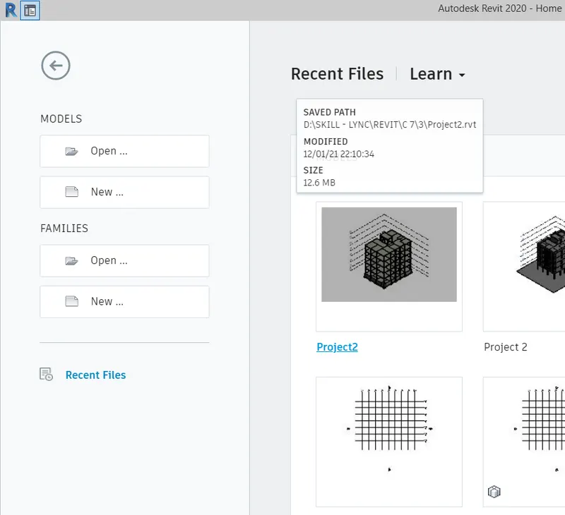
STEP 1 : TO OPEN THE STRUCTURAL MODEL OF THE WEEK 7 PROJECT
DOBLE CLICK ON REVIT ICON
SELECT THE WEEK 7 PROJECT IN HOME PAGE
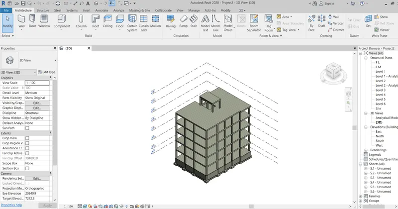
THEN OPENING THE STRUCTURAL MODEL
THEN GO TO PROJECTBROWSER
SELECT THE ANALYTICAL MODEL
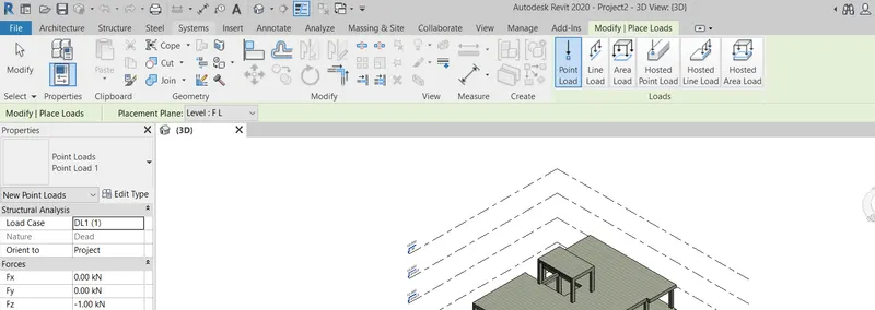
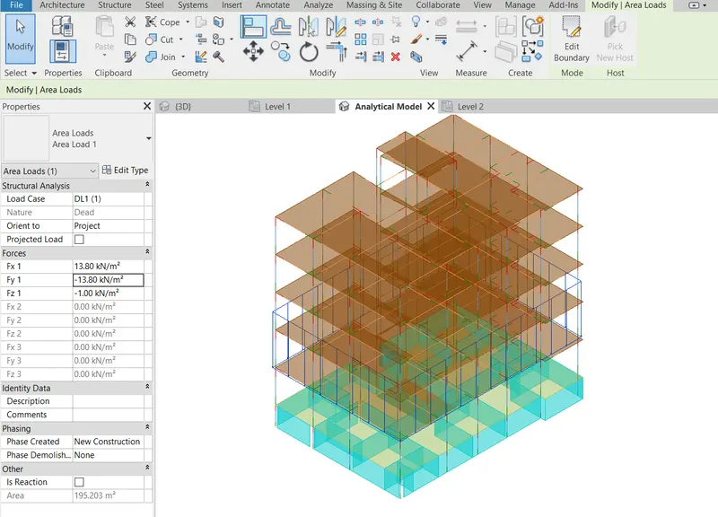
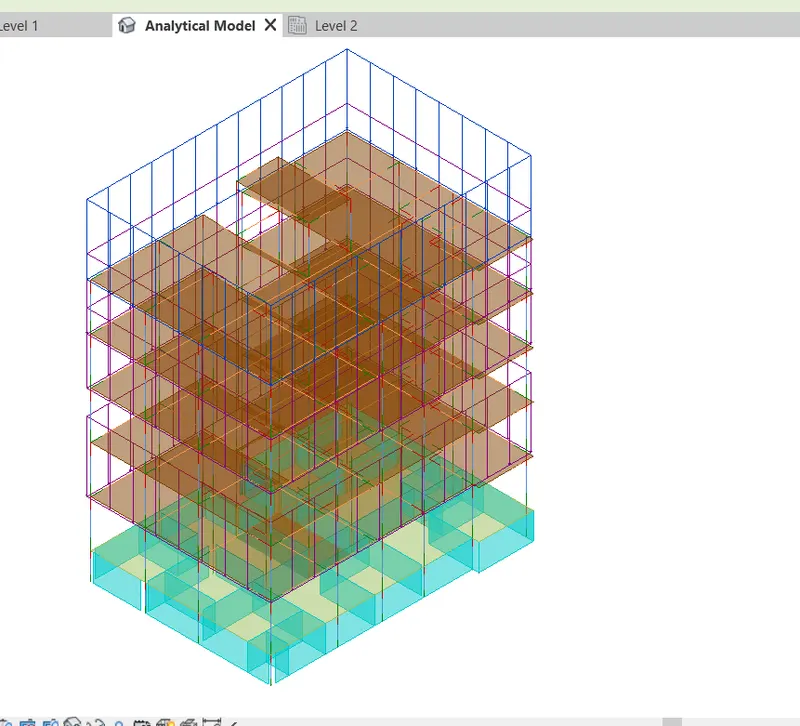
STEP 2 : TO ADDING THE LOADINGS
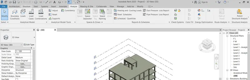
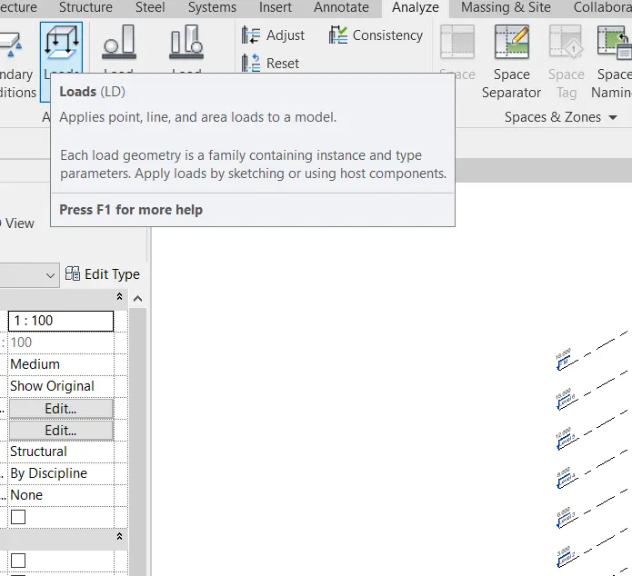
GO TO ANALYZE TAB
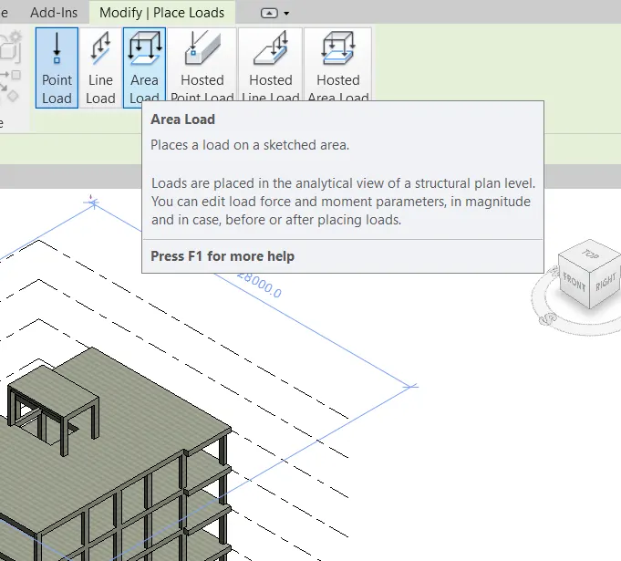
GO TO LOAD OPTION
TAKE THE REQUIRED LOAD CONDITIONS
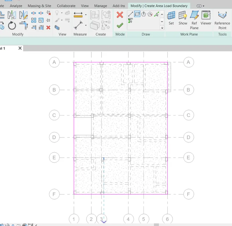
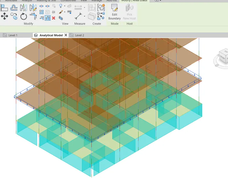
THEN APPLIED THE LOAD AS YOUR REQUIRED
THEN SELECT THE LOAD
THEN CHANGE THE LOAD PRAMETERS IN PROPERTIES PANEL
THEN SELECT THE LOAD
CLICK ON COPY TO CLIPBOARD IN MODIFY TAB
THEN GO TO PASTE OPTION
THEN SELECT THE ALIGNED TO SELECTED LEVELS
THEN SELECT THE REQUIRED LEVELS
CLICK ON OK
STEP 3 : TO ADDING THE LOAD CASES
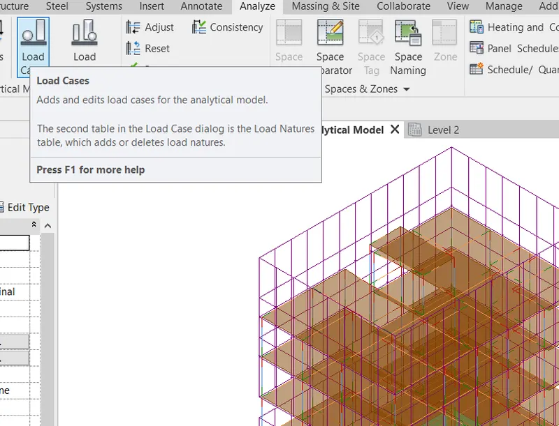
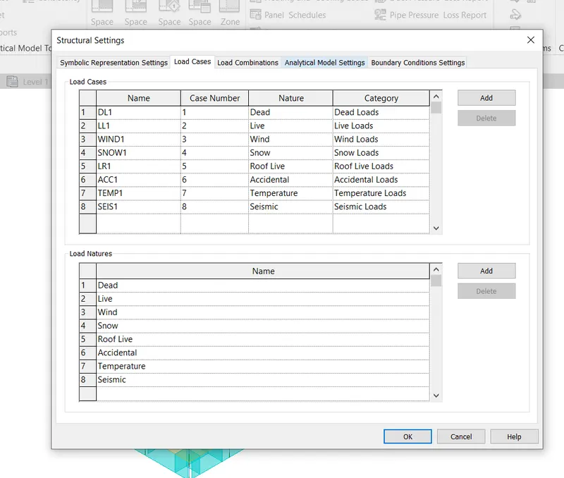
GO TO ANALYZE TAB
GO TO LOAD CASES OPTION
CLICK ADD
SELECT REQURIED LOAD
FINALY CLICK OK
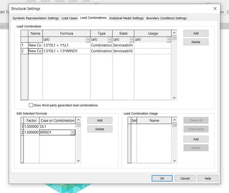
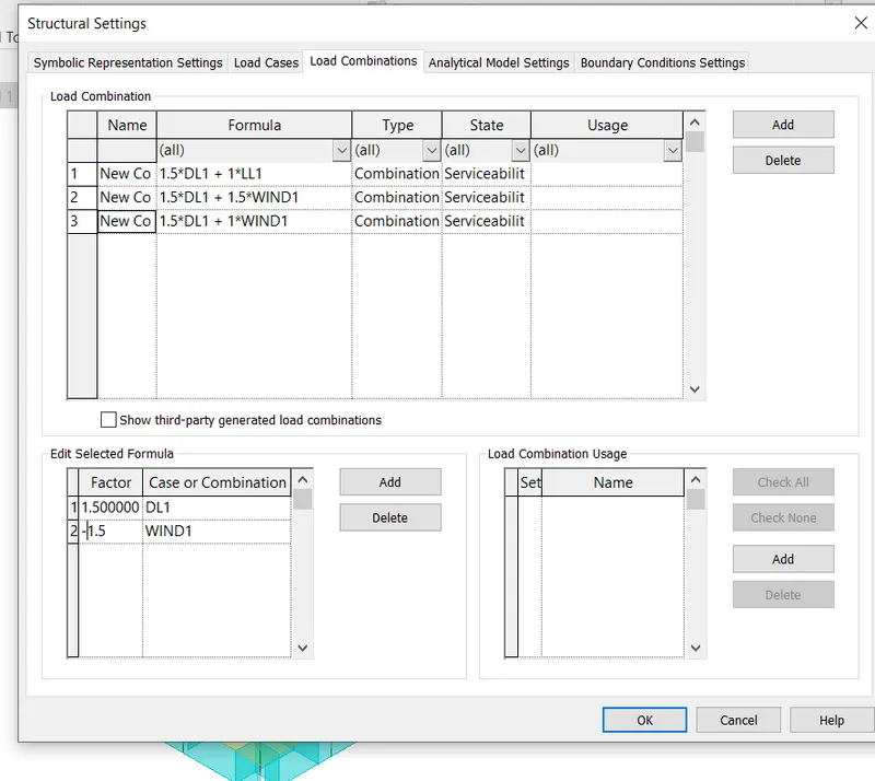
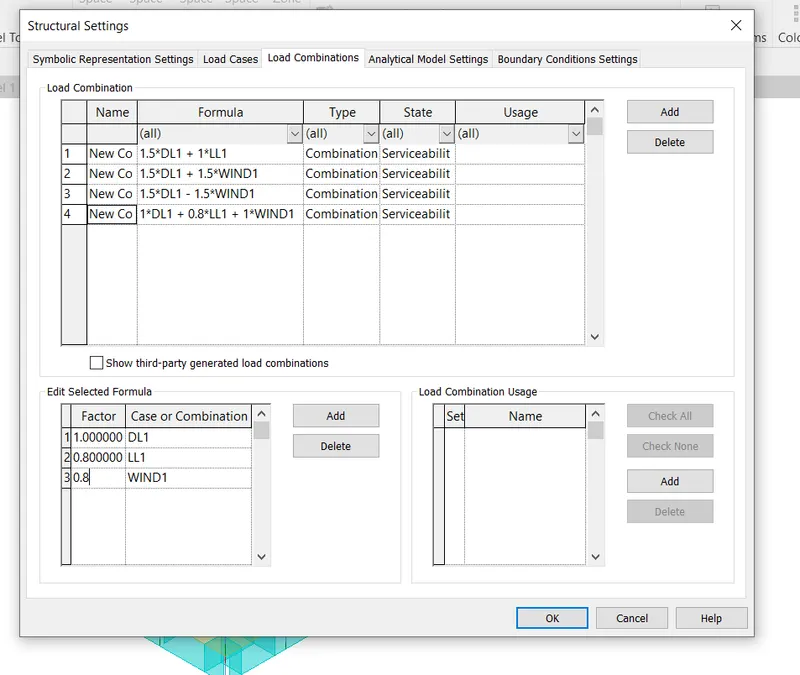
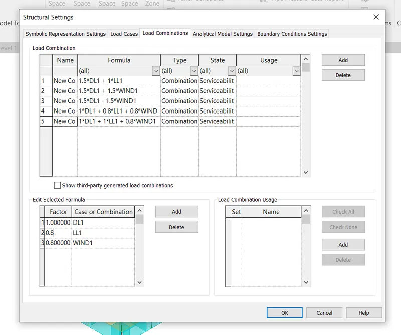
STEP 4 : TO ADDING THE LOAD COMBINATIONS
GO TO ANALYZE TAB
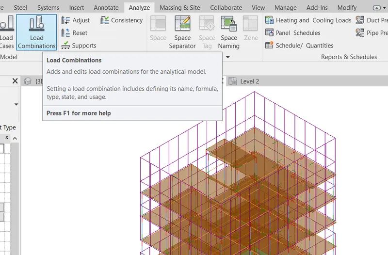
GO TO LOAD COMBINATIONS OPTION
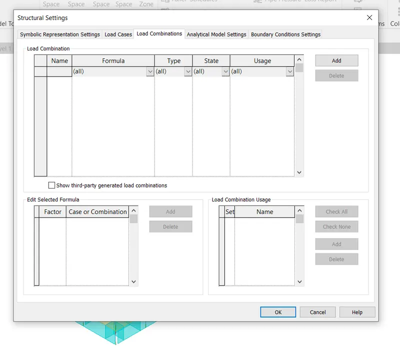
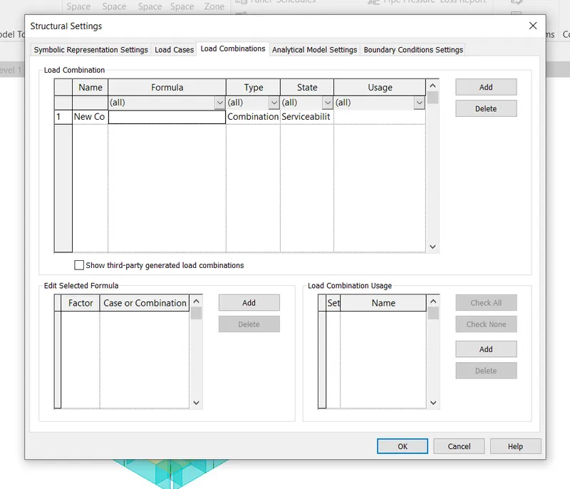
THEN CLICK ADD AT LOAD COMBINATIONS
THEN GIVE THE LOAD COMBINATIONS NAME
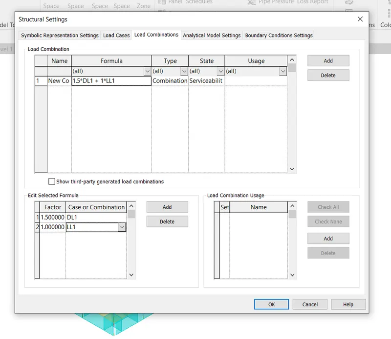
THEN CLICK ON ADD AT EDIT SELECTED FORMULA
THEN CLICK ON ADD REQUIRED TIMES
THEN SELECT THE REQUIRED LOADS
THEN GO THE REQUIRED FACTORS VALUE
AGIN SAME PROCEDURE WE CAN DO
THEN CREATE THE REQUIRED LOAD COMBINATIONS
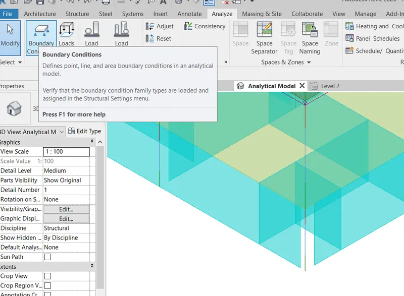
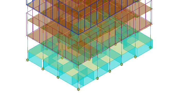
STEP 5 : TO ADDING THE BOUNDARY COMBINATIONS
GO TO ANALYZE TAB
GO TO BOUNDARY COMBINATIONS OPTION
SELECT THE SUPPORT TYPE AS FIXED
SELECT THE FOUNDATION ANALYTICAL POINT TO CREATE THE FIXED SUPPORT
NOTE : ANALYSIS IN CLOUD NOT BE FOUND IN MY LAPTOP
STEP 6 : TO EXPORT THE ROBOT STRUCTURAL ANALYSIS
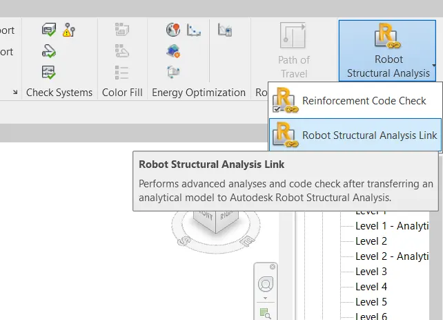
GO TO ANALYZE TAB
CLICK ON DROP DOWN ARROW ON THE ROBOT STRUCTURAL ANALYSIS TOOL KIT
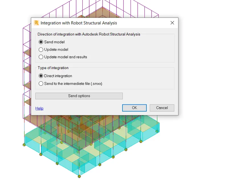
CLICK ON ROBOT STRUCTURAL LINK
FINALY CLICK ON OK
THEN OPEN THE MODEL IN ROBOT STRUCTURAL ANALYSIS SOFTWARE
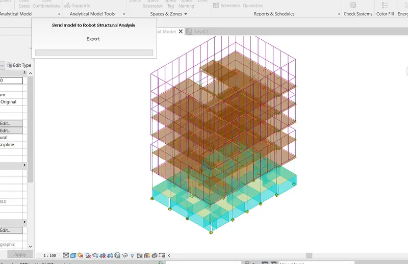
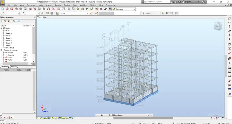
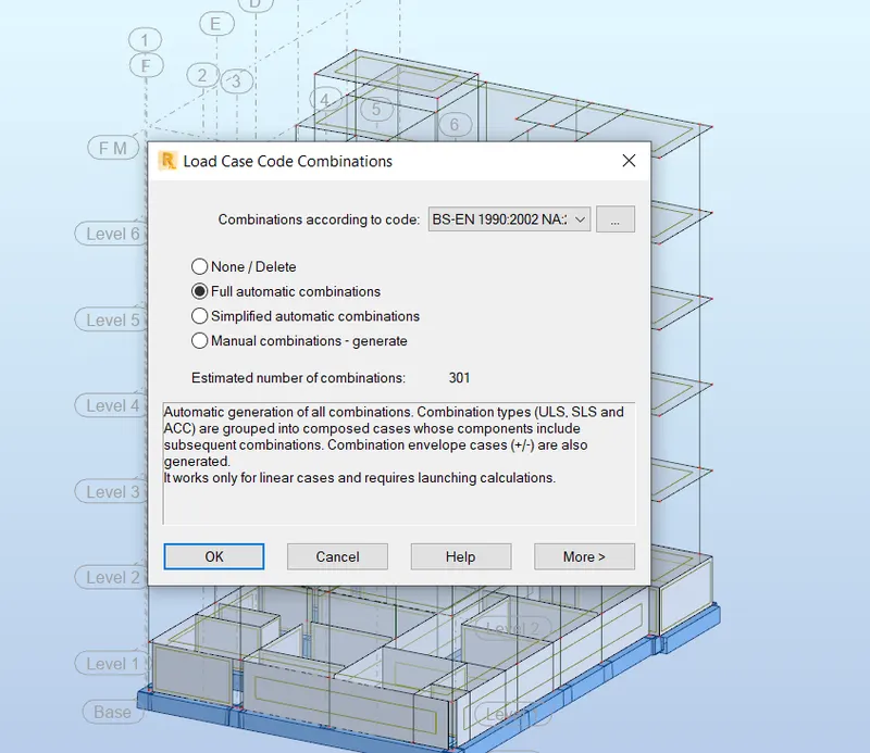
STEP 7 : TO ADDING THE LOAD COMBINATIONS IN ROBOT STRUCTURAL ANALYSIS
GO TO LOAD TAB
SELECT THE AUTOMATIC COMBINATIONS
THEN SELECT FULL AUTOMATIC COMBINATIONS
CLICK ON OK
FINALY TO SET THE LOAD COMBINATIONS
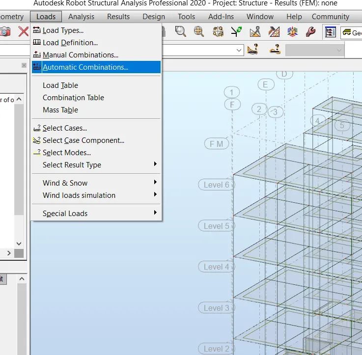
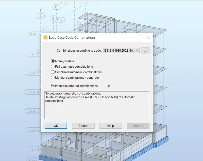
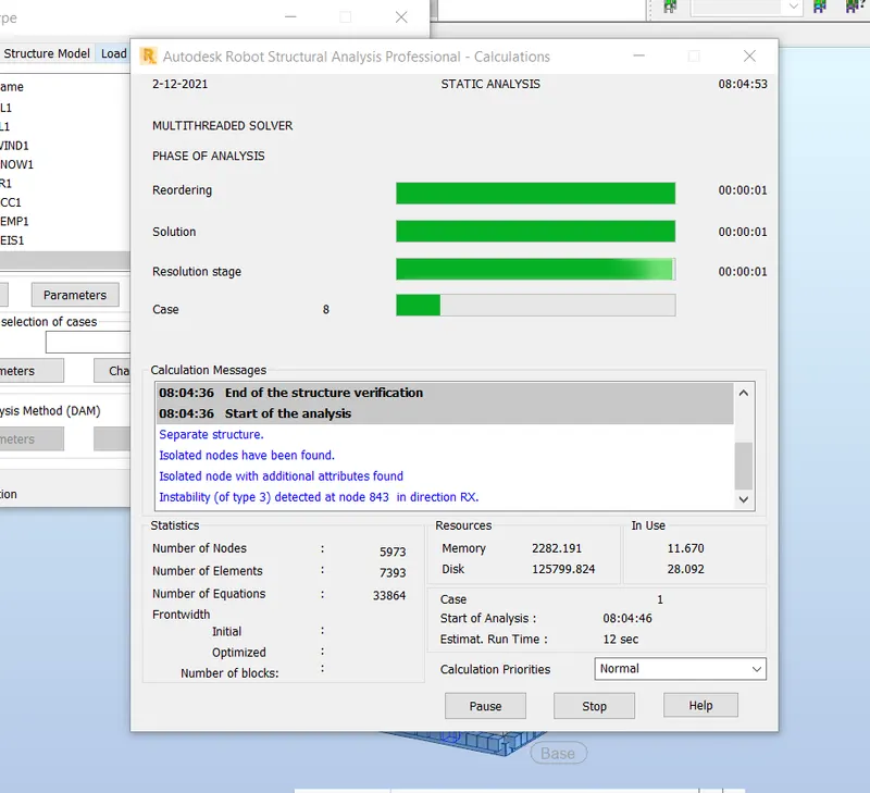
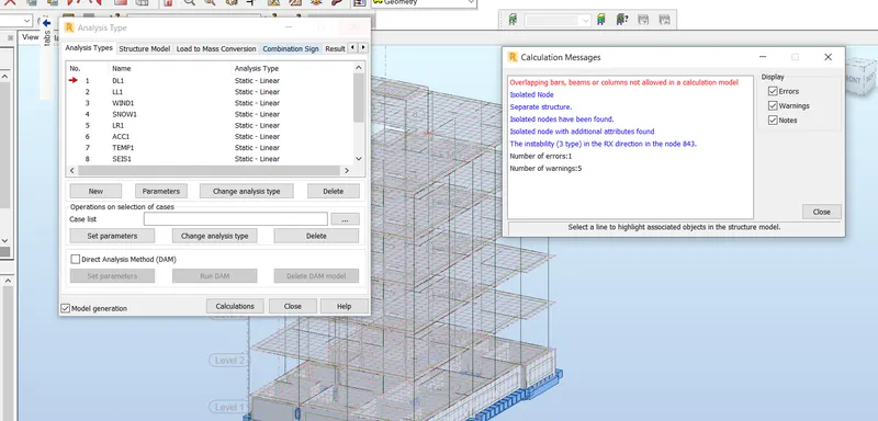
STEP 8 : TO DO ANALYSIS IN ROBOT STRUCTURAL ANALYSIS SOFTWARE
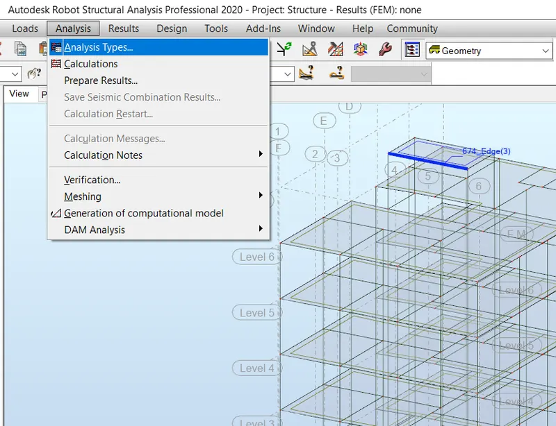
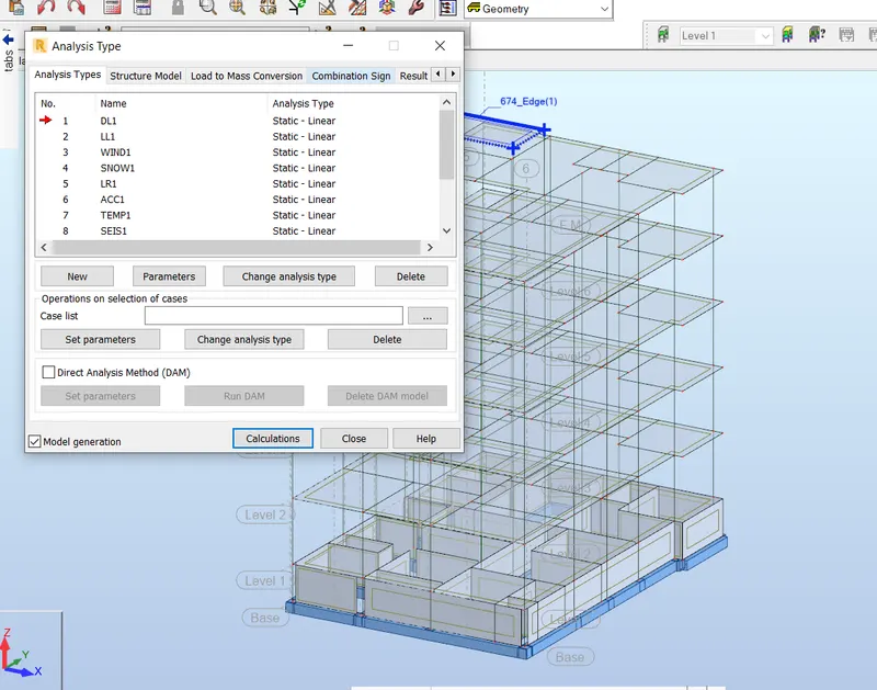
GO TO ANALYSIS TAB
SELECT THE ANALYSIS TYPE
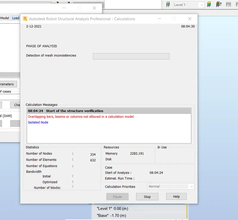
THEN CLICK ON CALCULATE
TO COMPUTE THE STRUCTURAL CALCULATION
STEP 9 : TO CHECK THE RESULTS
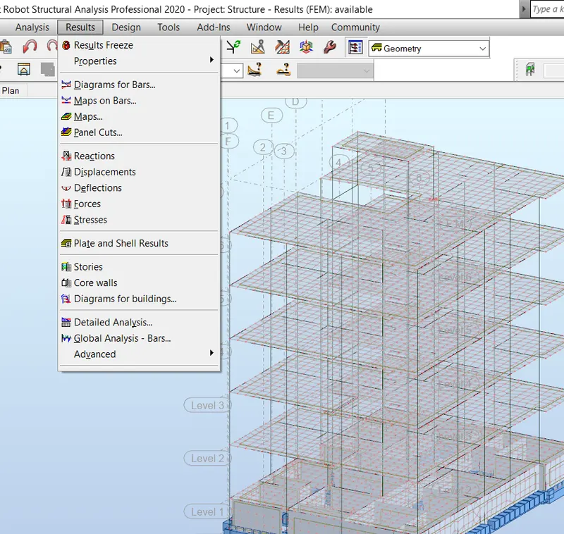
GO TO RESULT TAB
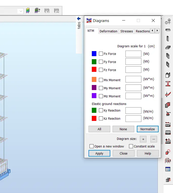
CLICK ON DIAGRAM AND BARS
TO CHECK THE ALL STRESSES
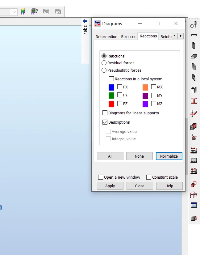
GO TO RECTIONS
THEN TURN ON REQUIRED PRAMETERS
CHECK TICK THE DESCRIPTION BOX
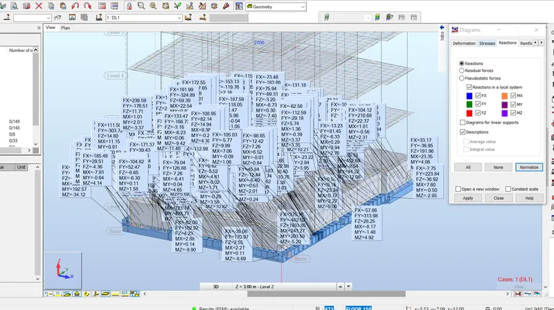
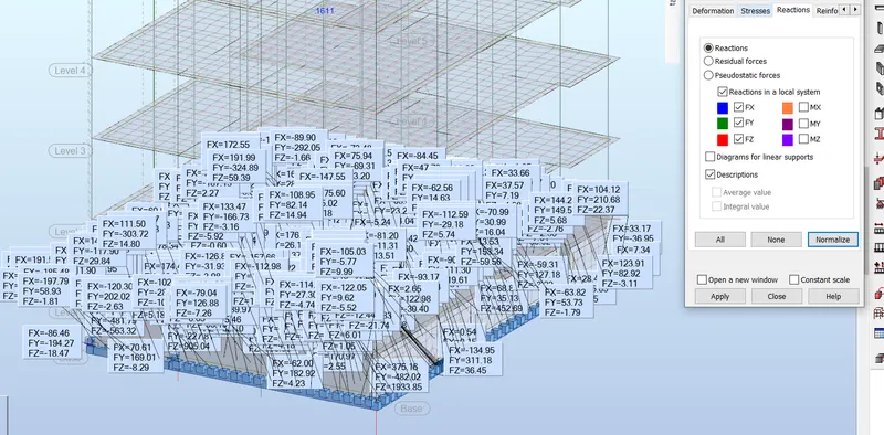
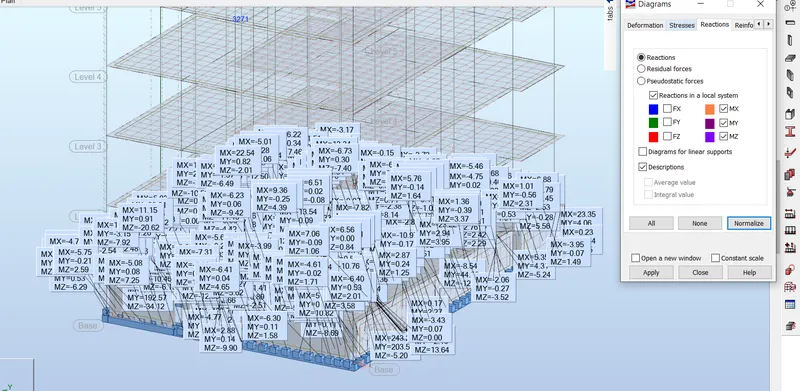
MOMENT RECTIONS RESULT FOR DEAD AND LIVE LOAD
SUPPORT RECTIONS RESULT FOR DEAD AND LIVE LOADS
RESULT :
TO EXPORTED THE COMPLETE ANALYTICAL MODEL TO ROBOT STRUCTURAL ANALYSIS SOFTWARE
6) What is energy analysis and why do we need to consider it while modeling in Revit?
How does the factor of sustainability improve the quality of your design?
Energy ana ysis is the traditionalmethod of assessingthe way energy is used inan operation involvingthe physicalor chemical processingof materials and the transfer and/or conversion of energy.
Energy usage analysis of buildings involves four principalsteps.
First is the ca culation of heatloss and gain to the buildingspaces and the heatingand coolingloads imposed uponthe bui ding HVAC systems.This ca culation is carried out for a space temperature f ixed in time and is common y called the Loads calculation. It answers the question:how much heat addition or extraction is required to maintain the space at a constant temperature as the outside weather conditions and internalactivity vary intime and the buidingmass absorbsand releases heat.
Second is the calculation of the energy addition and extraction actually to be supplied by the HVAC system in order to meet the possib y vary ingtemperature set-points and humidity criteria subject to the schedu es of fans. boilers. and chillers. and to outside air requirements.This calculation results in the demand for energy that is made onthe primary energy sources of the building. This step,called the Systems ca culation,answers the question:How arethe accumulative heat extraction and addition rates modified whenthe characteristics of the HVAC system,the time-varying temperature set-points,and the heating,coolingand fanschedules are taken into account?
The third is the determination of the fuelrequirements of primary equipment such as boiers and chillers,and of the energy production of solar collectors,etc.,in the attempt to supply the energy demand of the HVAC systems. This Plant ca culation answers the question: how muchfueland e ectricalinput is required to feed the secondary HVAC system given the efficiency and operatingcharacteristics of,the plant equipment and components.
The fourth step eva uates the costs of equipment,f ue ,electricity,labor,and retrofit components against the alternative of investingthe money inother ways. It answers the question: Is the expenditure of funds for energy conserving materials and systems cost-effective when compared with alternative systems and investment possibilities? This step is called Economics calculation
SUSTAINABLE DESIGN
Sustainable design seeks to reduce negative impacts on the environment,and the health and comfort of bui dingoccupants.thereby improvingbuilding performance.The basic objectives of sustainability are to reduce the consumption of non-renewable resources. minimize waste,and create healthy,productive environments.
Sustainable design principles include the ability to:
optimize site potentia ;
minimize non-renewable energy consumption;
use environmentally preferable products;
protect and conserve water;
enhance indoor environmentalquality;and
optimize operationaland maintenance practices.
Utilizinga sustainable design philosophy encourages decisions at each phase of the design process that willreduce negative impacts on the environment and the health of the occupants,without compromisingthe bottom line.It is anintegrated,holistic approach that encourages compromise and tradeoffs. Suchan integrated approach positively impacts all phases of a building's life-cycle, including design,construction,operation,and decommissioning.