Structural analysis of a buidling using Robot Structural Analysis
1. Aim:- To explain about HVAC systems and the essentials in the modeling of buildings.
Introduction:- To explain about HVAC systems and the essentials in the modeling of buildings.
Procedure:-
- HVAC stands for Heating, Ventilation and Air conditioning.
- It is a technology of indoor environmental comfort. Its goal is to provide thermal comfort and acceptable indoor air quality.
- It is a Important part of residential structures such as single familt homes such as Apartments, Hotels and Senior citizen facility and medium to large industrial office buildings such as office and hospitals.
Essentials in building modelling:
- HVAC designs are used for controlling the overall climate of the building.
- It balances the temparature to make the inside cool or warmer during the cold conditions.
- The Boilers and coolers are opened during the colder days.
- It enhances the productivity in offices as they feel comfortable.
- HVAC improves the air quality in the building making it ppropriate for human breathing and comfortness.
- It reduces humidity so residence can feel together.
- HVAC also helps you to acheive more savings.
- It acheive the energy efficiency.
2. Aim:- To create based on the building designed use the same Revit file to design a HVAC system for each floor.
Introduction: To create based on the building designed use the same Revit file to design a HVAC system for each floor.
Procedure:
- First we need to open the revit software.
- Then open New file.
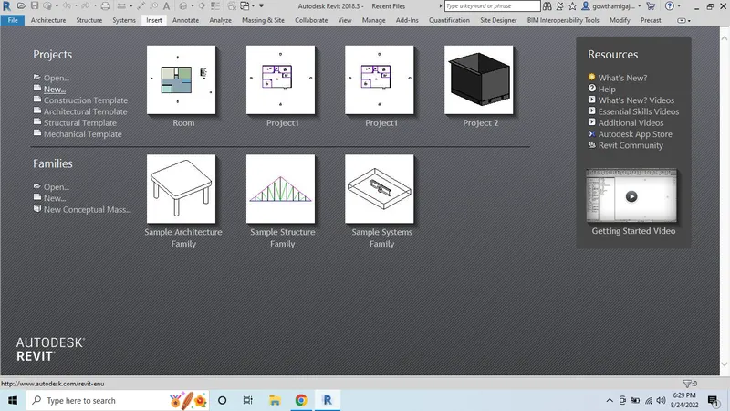
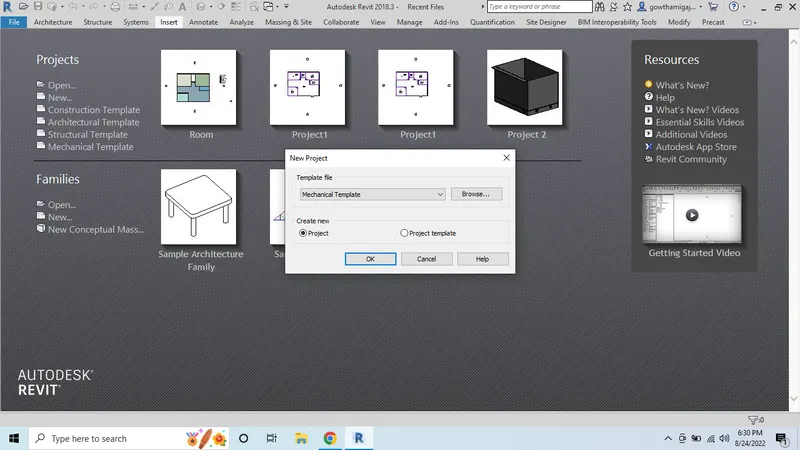
- To create the HVAC drawings we need to open the mechanical template.
- Then choose Mechanical template.
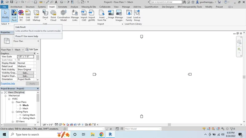
- Then go to Insert tab.
- And choose to link revit option.
- Then open any existing drawing which is available previously.
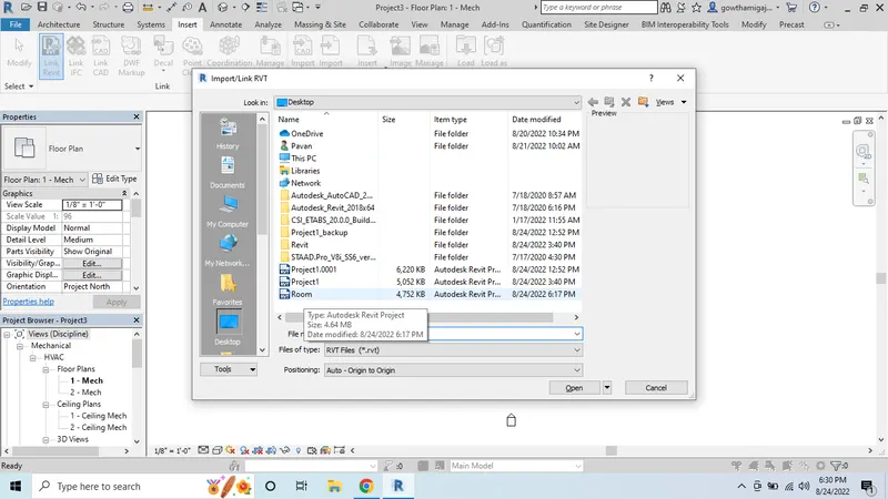
- Then the drawing will open as a link in the drawing.
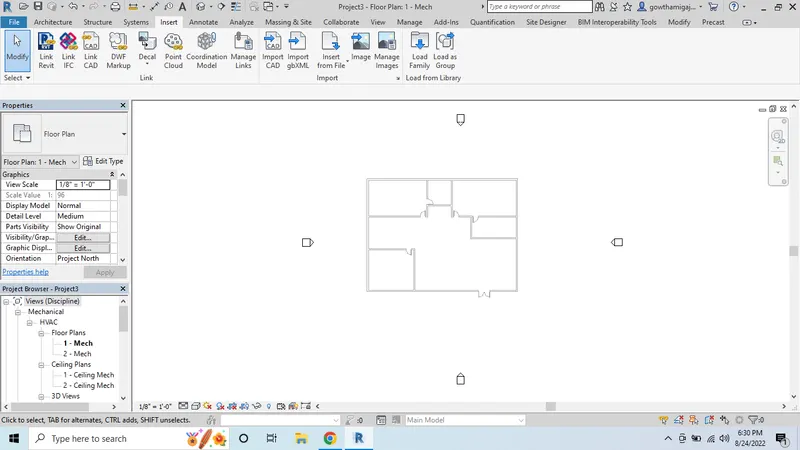
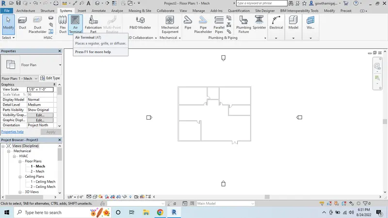
- Then go to systems tab in the module tab.
- Then choose Air terminal option from the system tab.
-
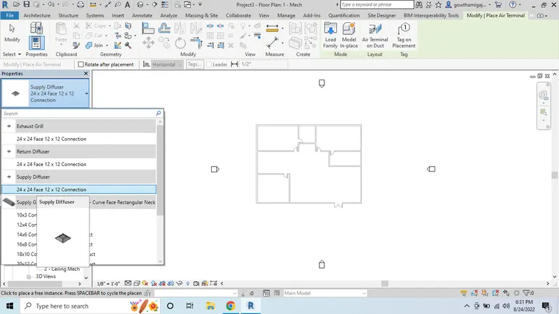
- Then choose supply diffuser with the proper size in the given options.
- Now place the supply diffuser in the plan in any room area.
- And place the 2 supply diffusers in the room.
-
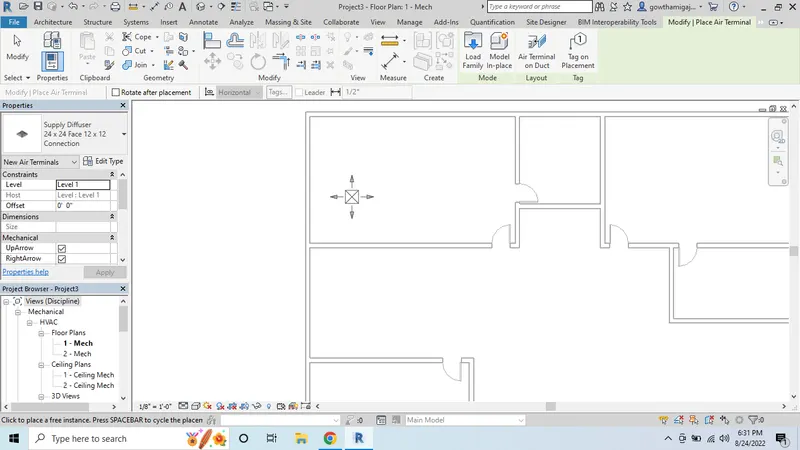
- Now we can see the 2 supply diffusers placed in the room.
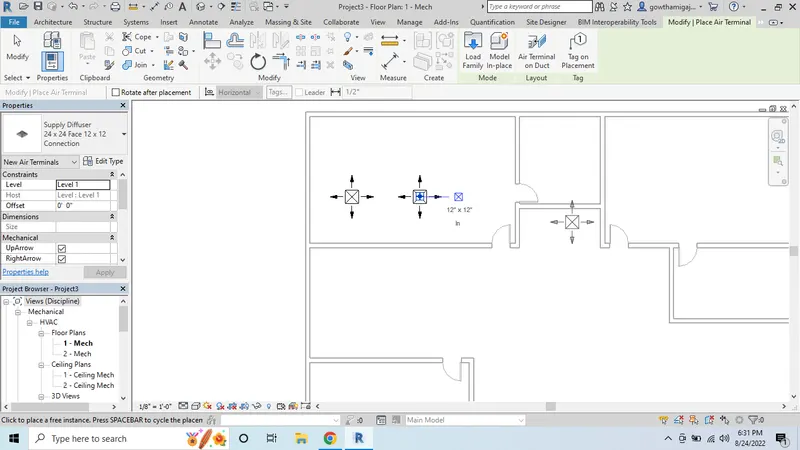
- Then again go to the system tab.
- Now choose the Mechanical equipment option.
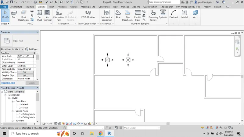
- Now choose the Mechanical equipment option.
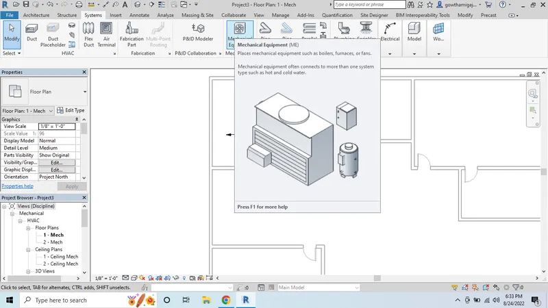
- Now click on the load family.
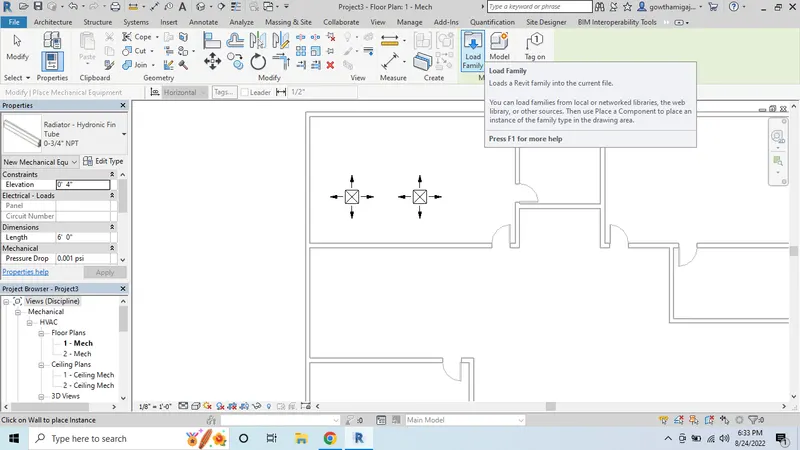
- Then go to the MEP folder.
- Select the Air side components from the folder.
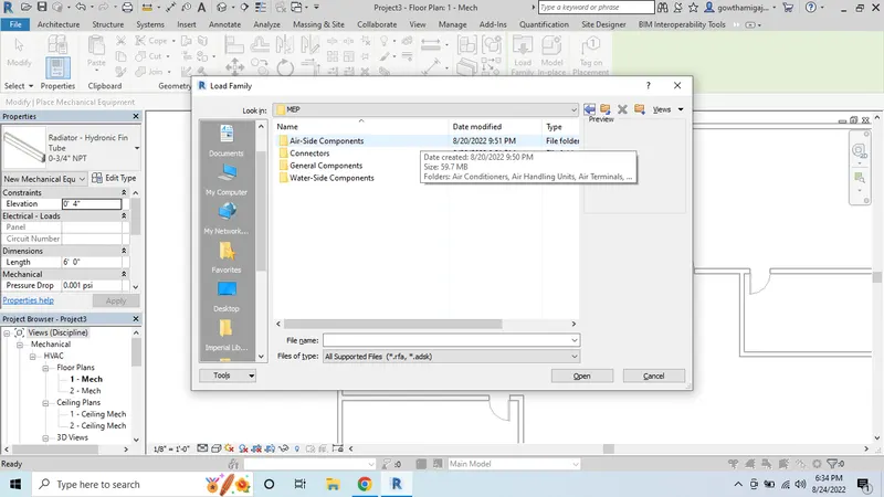
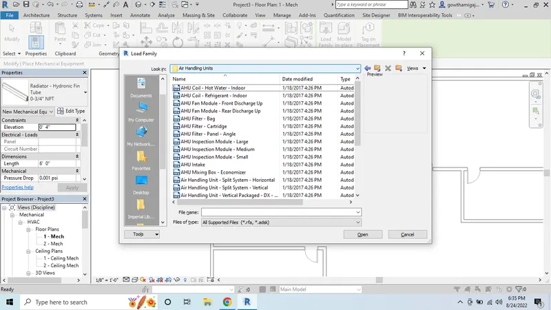
- Now choose from the list of any coil.
- And now place it in the drawing.
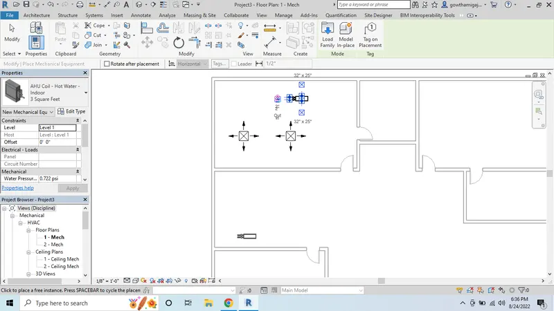
- Now select the 3 points.
-
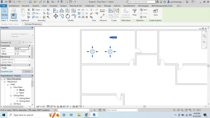
- Now select the duct option from the menu tab.
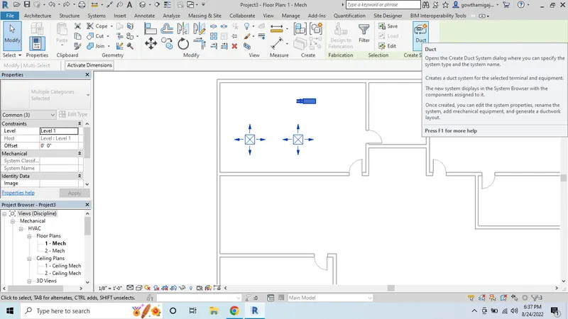
- Then the dialogue box will get open.
- Now choose the supply air option.
- And click on Ok.
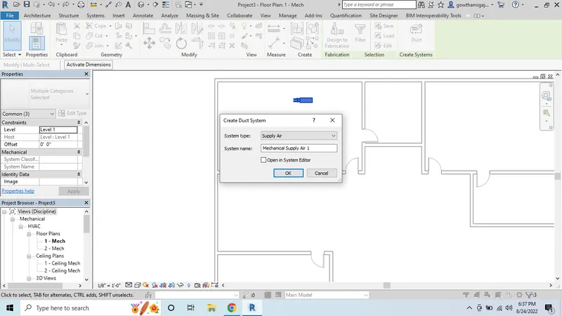
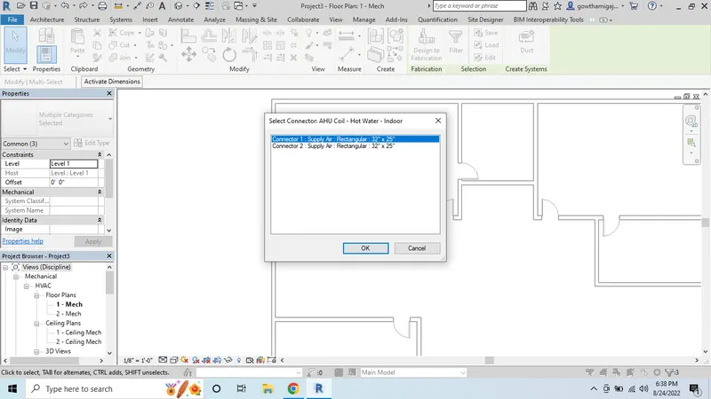
- Then we can get the dialogue box for selecting the connectors.
- Now select any one connector based on the drawing.
- And click OK.
- Now choose the generate option.
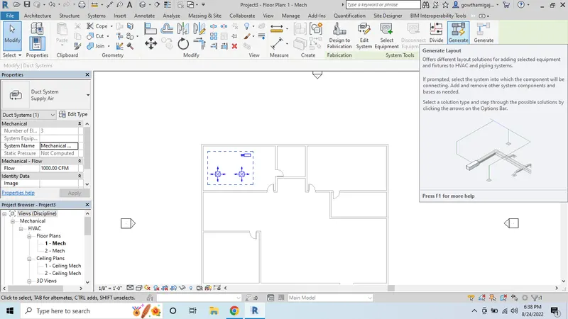
- Then from the option choose the direction of the connectors.
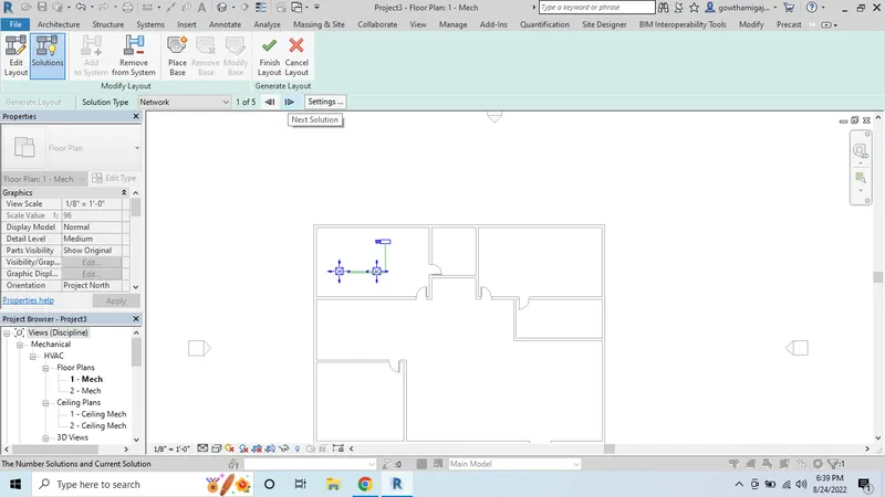
- And click on the Finish option.
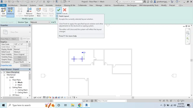
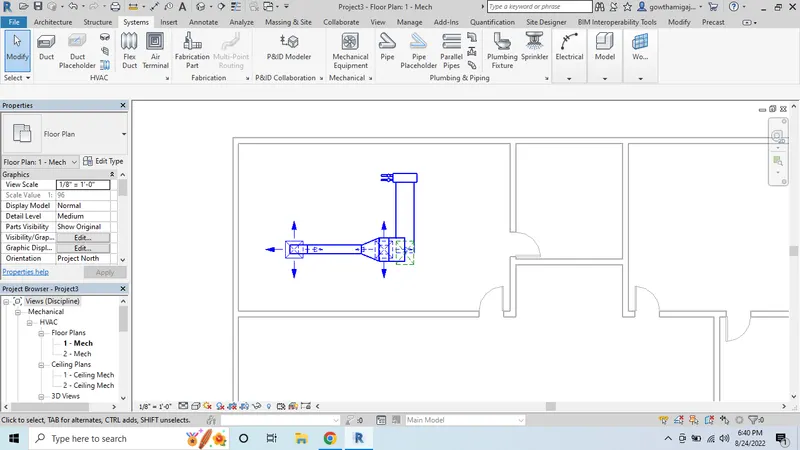
- Now we can see the HVAC connector in the drawing.
- Then go to the 3D view option.
-
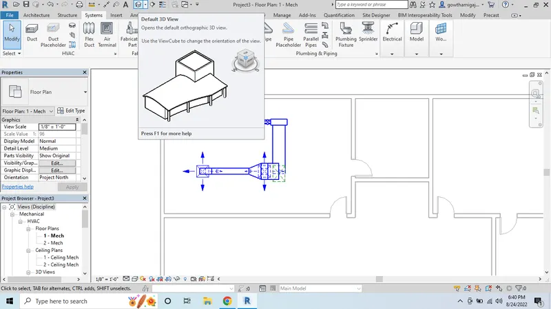
- And finally we can see the HVAC connector in the drawing.

Result:
3. Aim: To create the add-ins tab to load plug ins for Robot structural analysis to your Revit software.
Introduction: To create the add-ins tab to load plug ins for Robot structural analysis to your Revit software.
Procedure:
- First we need to open the revit software and open any drawing.
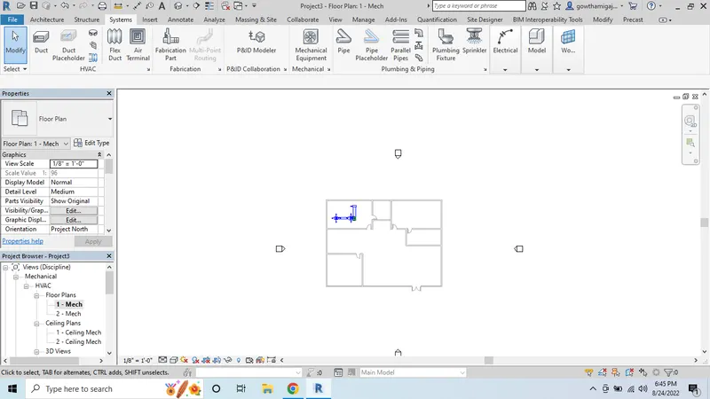
- For getting the robot structural analysis option, go to the shop option on the right side of the drawing.
- Click on the image.
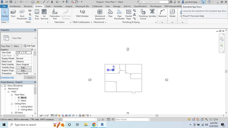
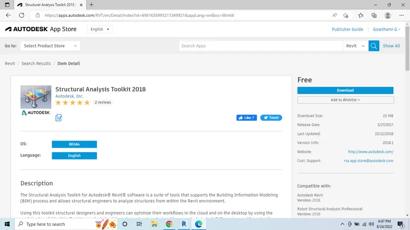
- It will redirect to the Autodesk home page.
- And type for the structural analysis toolkit and year of your revit software version on the search bar.
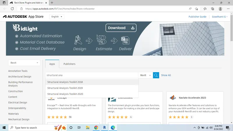
- Then we can see the tool kit opened below the icon.
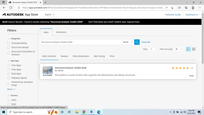
- Now click on the link.
- And click on the download option after opening the link.
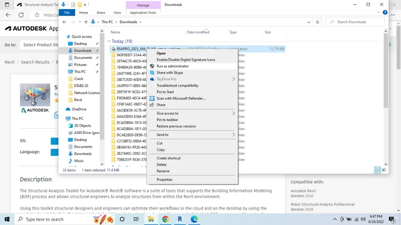
- Then after downloaded the file go to the download folder.
- And now select and do right click and select run as administrator option.
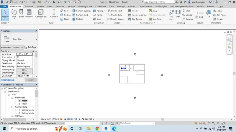
- Then after the installation process is completed again open the drawing.
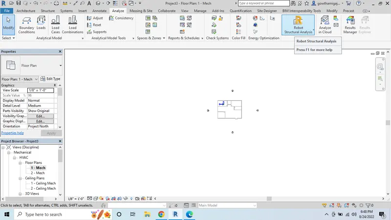
- Now click on the analyze tab.
- Now we can see the Robot structural analysis option in the analyze tab.
- After doing this, still if we can't get the Robot Structural analysis option, there is another way of getting this.
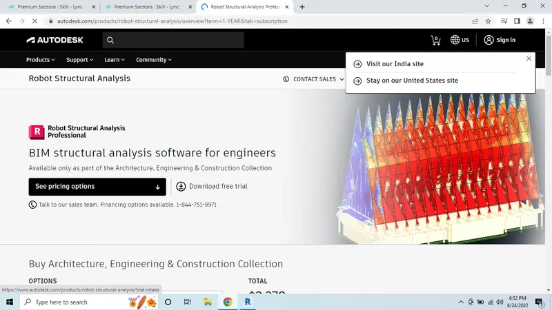
- Go to the Google and type Robot Structural analysis 2018 and click enter.

- Then select the second link.
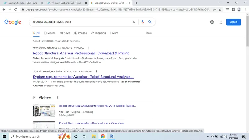
- Now go to the products option.
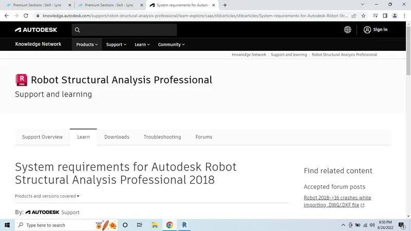
- Click on View all products.
-
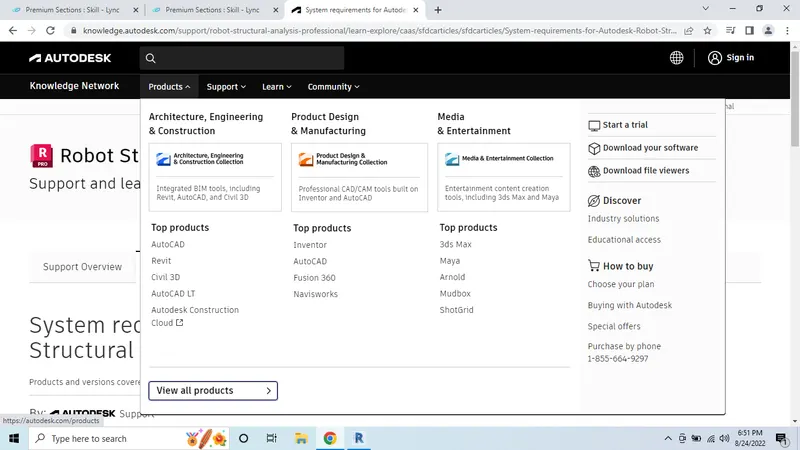
- Then search for the Robot Structural analysis icon.
- And click on the Robot Structural analysis link option.
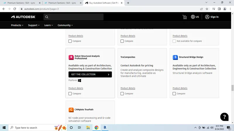
- Now click on the download option.
- Then the file will get downloaded.
- After downloading the file, select the file and right click and select run as administrator.
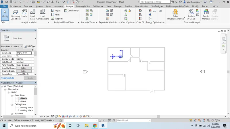
- After the installation process is completed we can see the Robot Structural analysis option in the analyze tab.
Result:-
4. Aim: To create the need to assess the building/analyze while modeling elements.
Introduction: To create the need to assess the building/analyze while modeling elements.
Procedure:
- Structural elements is essential in modeling elements as it helps in determining the loads and internal forces on a structural building or in any object.
- It is particularly imported for structural engineers to ensure that understands the load bars and impact the loads and to cross check the internal loads.
- Structural engineer can perform a during design, testing and for post construction process.
- It also ensures that a piece of equipment on a structure is safe for use under the estimated loads.
- Generally it can use in the geometry of the strucures in the applied loads.
- Structural analyse is usually looks at an individual structural elements and forces they undergo.
- Then structural engineer looks at an structural analysis for all the structural components like the slabs, cables and walls.
- All of these elements have forces and applied wind load, live load and dead load for all the loads which we based in the building.
- And yes, it effects the structural modeling in anyways.
- So it is important for the engineer to review each of these elements under these loads.
5. Aim: To model a structural drawing developed in week 6 and 7 in the analytical model to Robot Structural Analysis method.
Introduction: To model a structural drawing developed in week 6 and 7 in the analytical model to Robot Structural Analysis method.
Procedure:
- First we need to open the revit software.
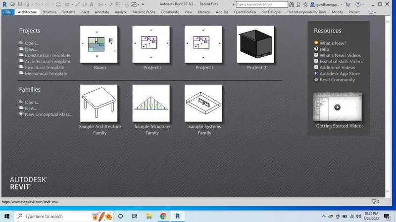
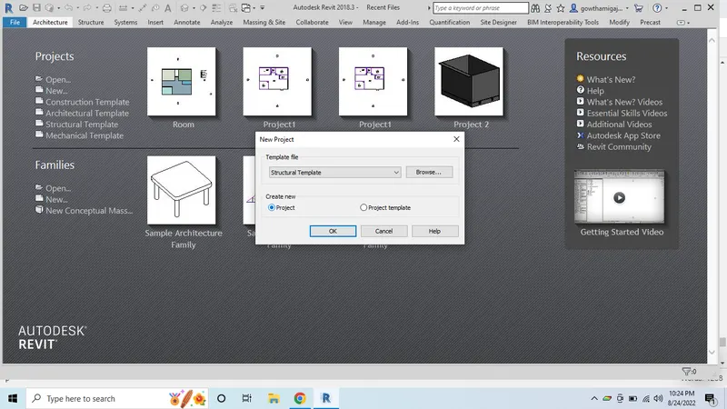
- Then go to the new template.
- Now select the structural template.
- Now open the structural drawing which is done on the 7th week challenge.
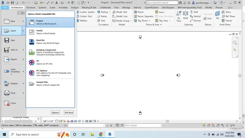
- Now the structural file is opened.
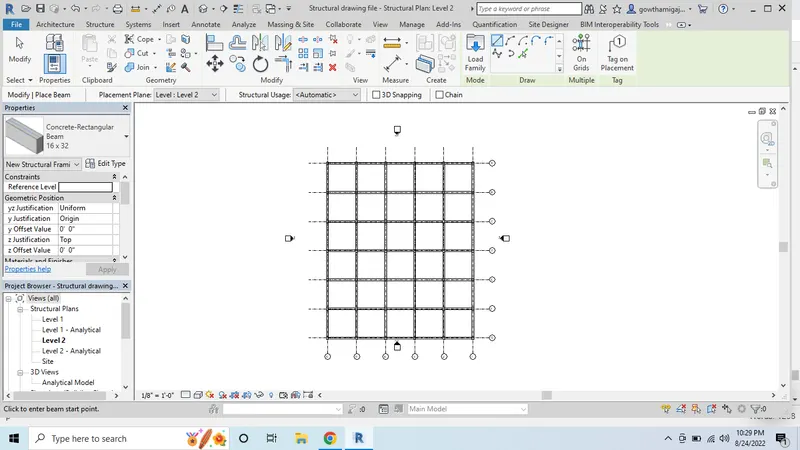
- Open the drawing in the 3D view.
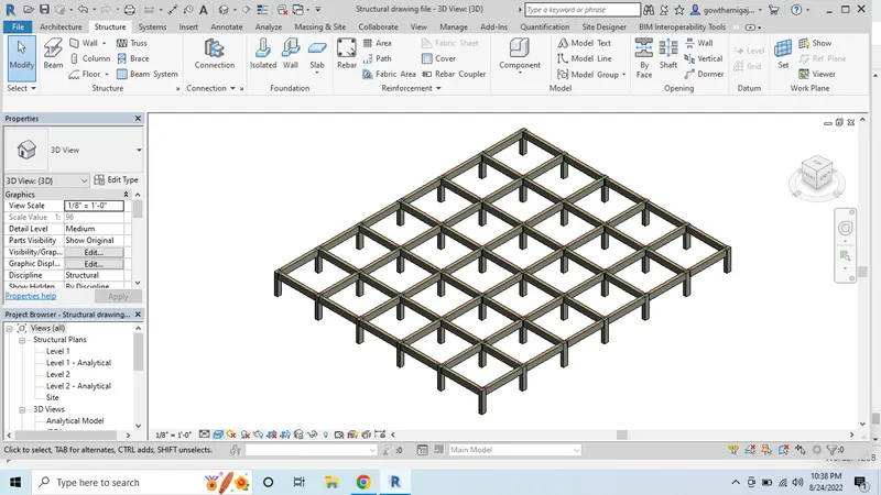
- Now structural drawing is ready and go to the manage tab.
- Then Robot Structural Analysis is ready.
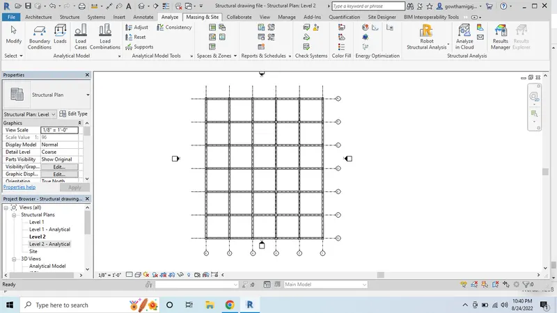
- Go to analyze tab.
- Then click on loads.
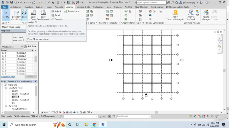
- Then modify tool bar will open.
- Then select rectangle or line command and draw the area line.
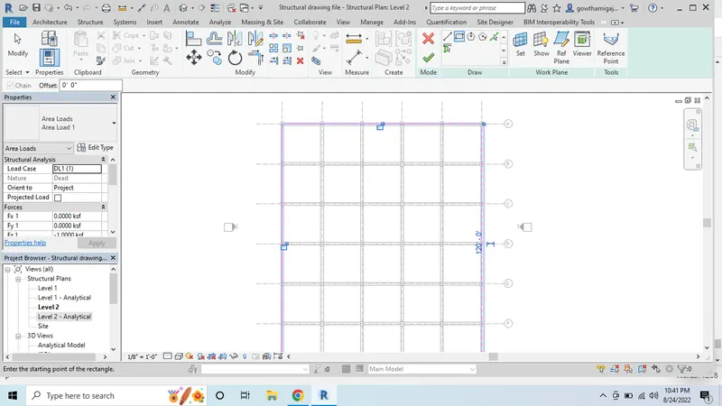
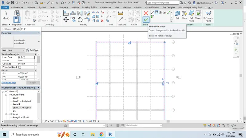
- After creating rectangle click on finish option.
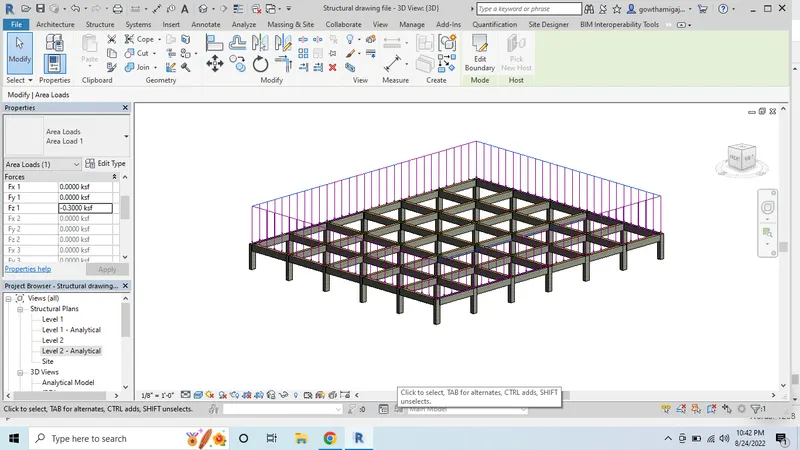
- Then go to 3D view option.
- There we can see the point load applied on the structure.
- Now click on load cases option.
- Then the dialogue get open.
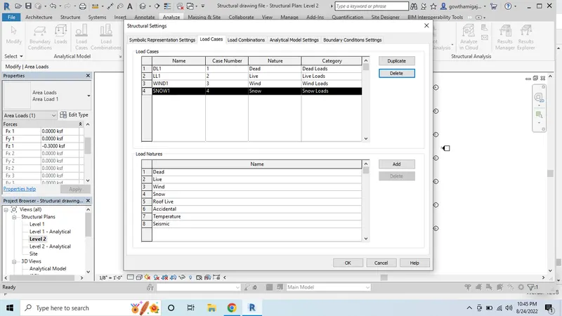
- In the dialogue we can add or delete the loads.
- Now there are some loads acting on the structure.
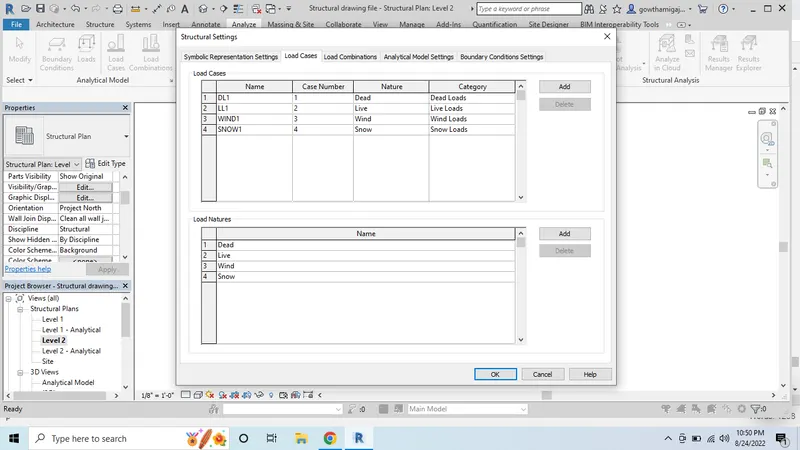
- Then click apply and close the dialogue box.
- Now the load is applied on the structure.
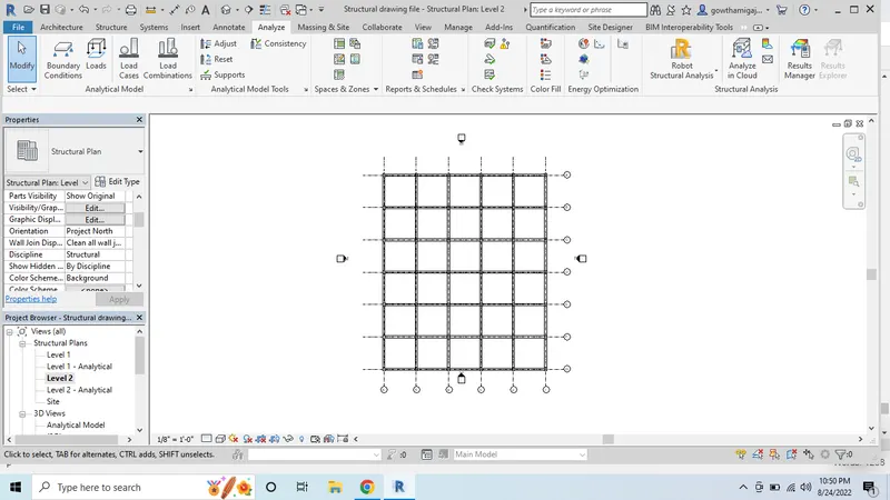
- Now go to analyze tab again and select load combinations option.
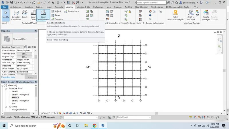
- Here in the load combination, we have to add the loads.
- When you click on the load combination option, a dialogue box will open.
- In that dialogue box, we have to add the load combinations.
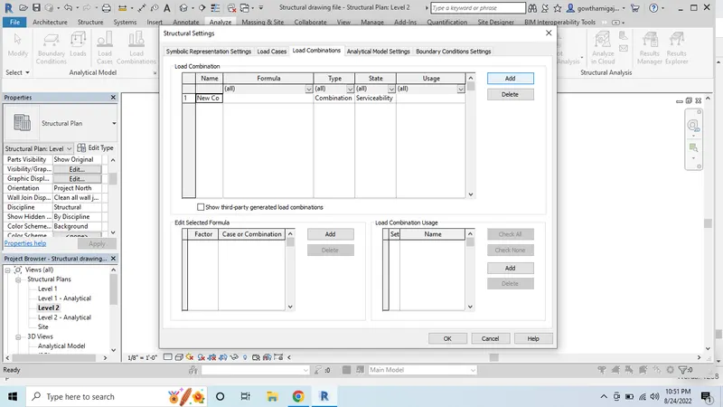
- Click on add option, and we have to add the load option.
- At the bottom, we have to give the load values of different types of loads.
- Now create the loads as per the structure and add the loads.
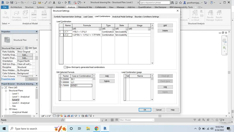
- Now after entering loads automatically load combination will generate.
- Now click on Ok.
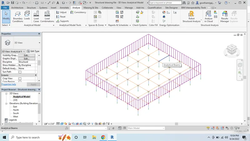
- Now go to 3D view option.
- We can see the loads applied on the structure.
- Now go to analyze tab.
- Select the boundary conditions option.
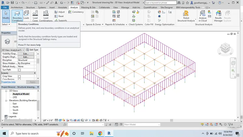
- Now select the loads as per the structure.
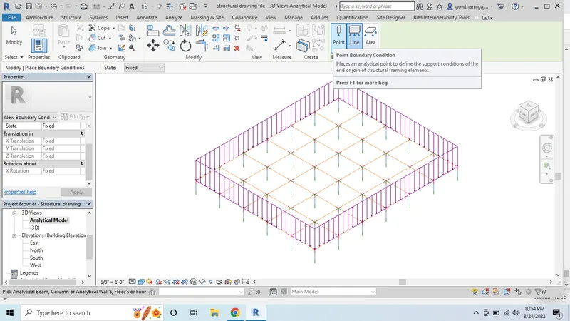
- Now place the load at the column end point.
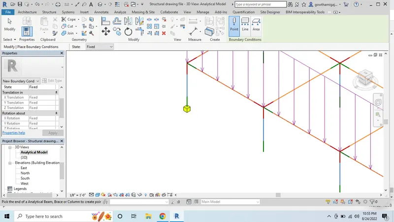
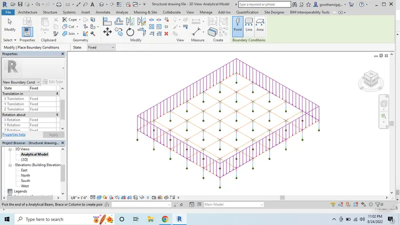
- Place the point load at all the columns.
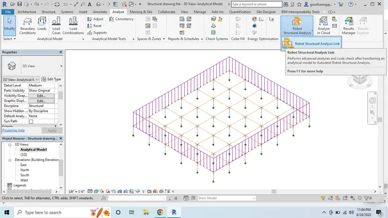
- Then go to the analyze tab and select Robot structural analysis option.

- Choose the option for the Robot structural analysis.
- Then the dialogue box appear on th screen and click on ok.
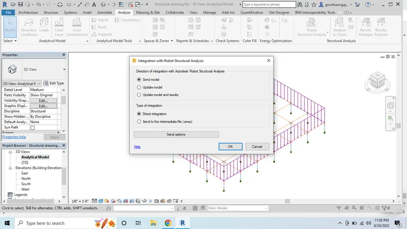
- We can see the process to open the structure in Robot structural analysis.
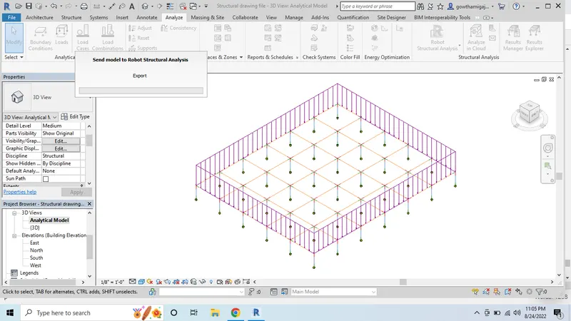
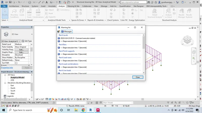
- After the process a dialogue box will appear and close the box.
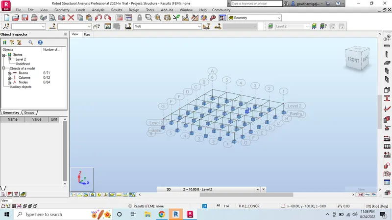
- Now we can the structure is opened in the Robot structural analysis
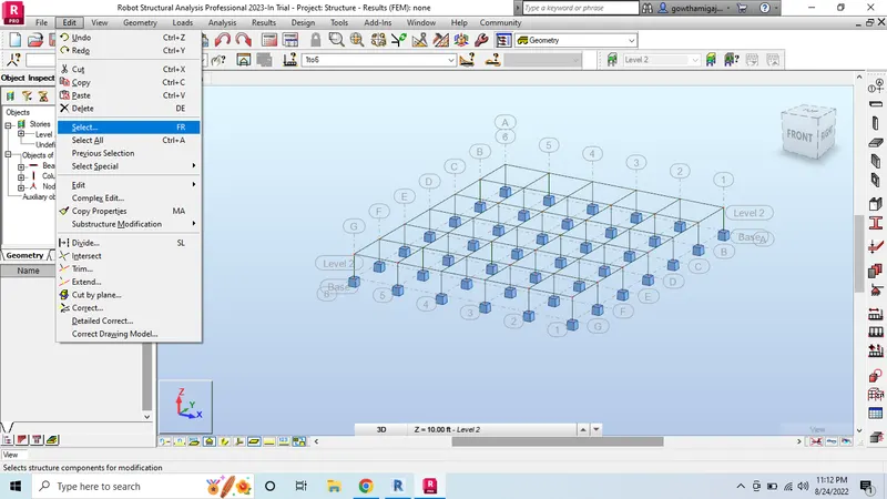
- Now go the edit command and choose select option to select all the levels.
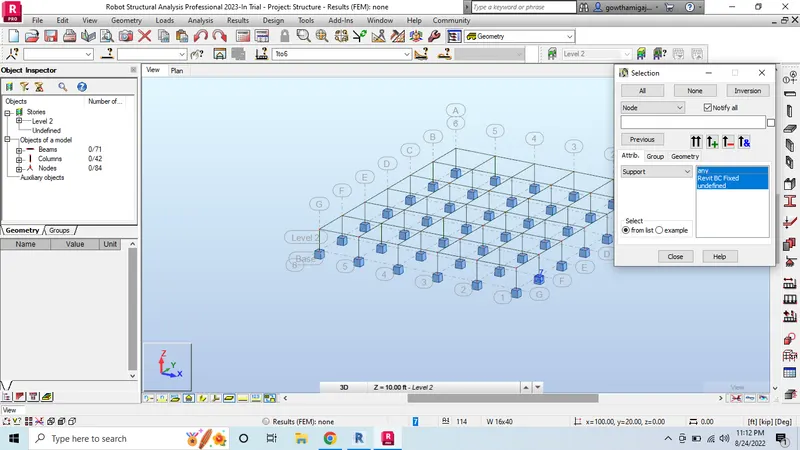
- Now we can see the dialogue box and Select all the options and close the dialogue box.
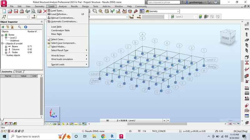
- Go to the loads command option.
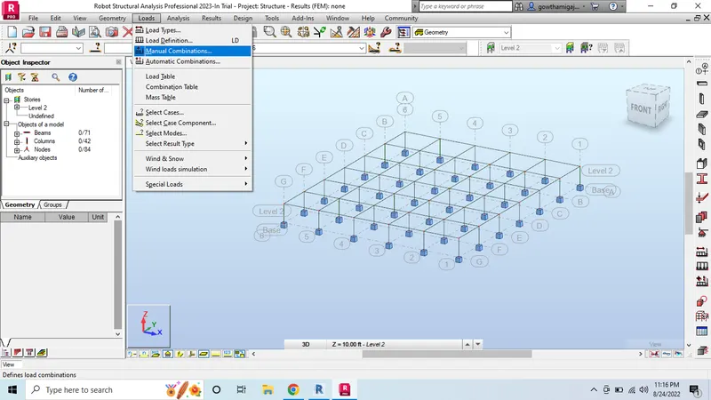
- Select the Manual combinations option.
- Now the dialogue box will appear.
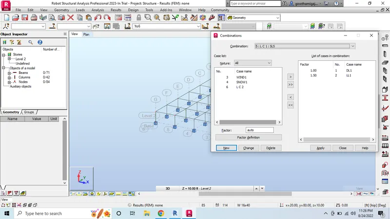
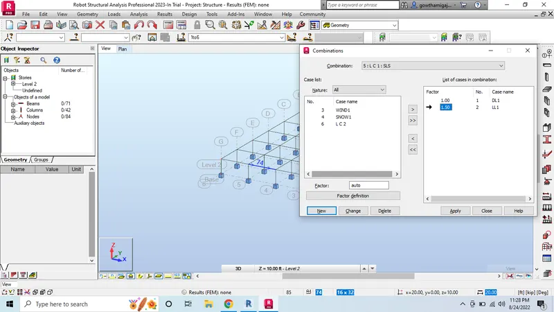
- Select the loads from the dialogu box.
- Click on apply option and close the dialogue box.
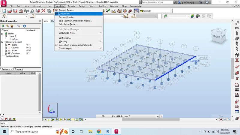
- Now go to analysis tab.
- Click on the calculations option.
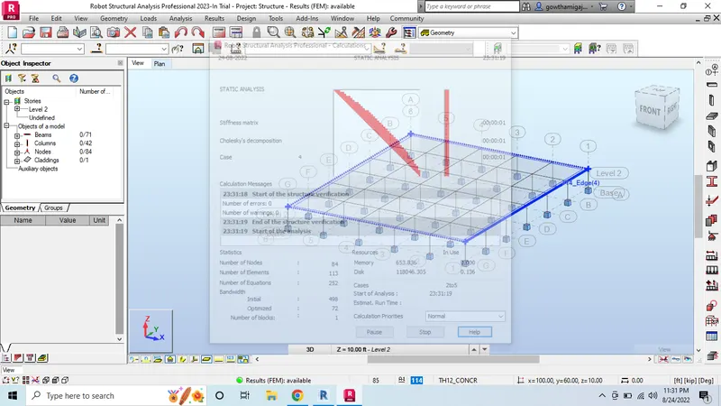
- Now the analysis process is going on in the drawing.
- Finally we can see the drawing after the applying the loads.
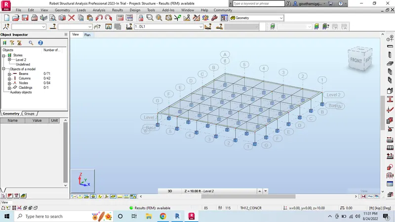
- Now go to results tab.
- Select the diagrams for members option.
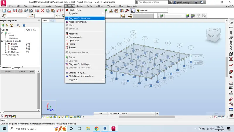
- Now the dialogue box will get open.
- Then select the loas form the dialogue box.
-
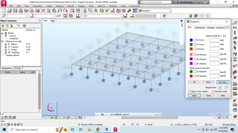
- After selecting the loads click apply and close option.
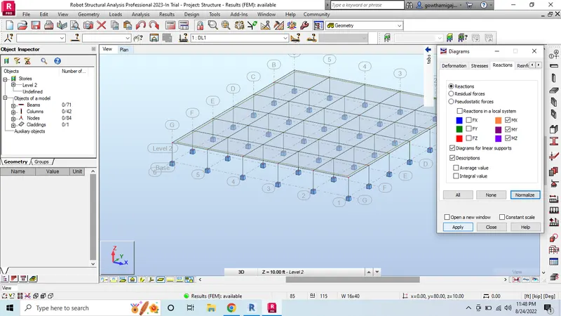
- Now we can see the loads applied on the structure.
- Then we can see the maximum bending moment loads applied on the structure.
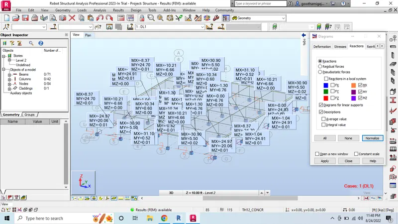
- In the same way select the forces from the dialogue box to get the force loads.
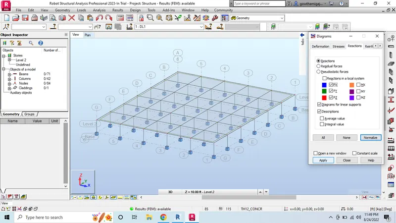
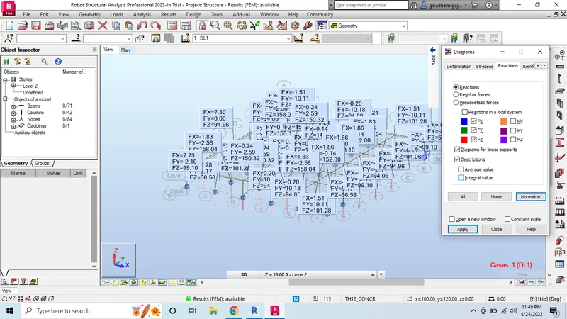
- Now we can see the force loads acting on the structure.
- In the same way, select the loads whatever necessary from the dialogue box.
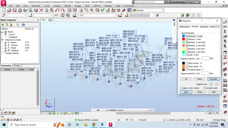
- Select the loads and apply and close.
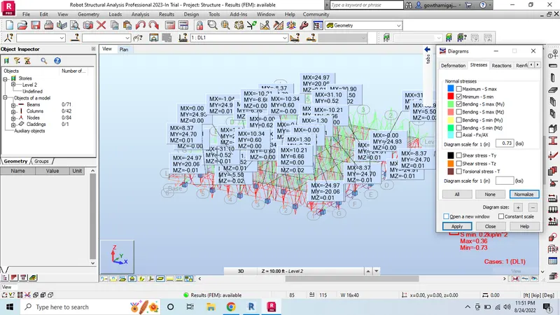
- Now we can see the final structure drawing after applying the loads.
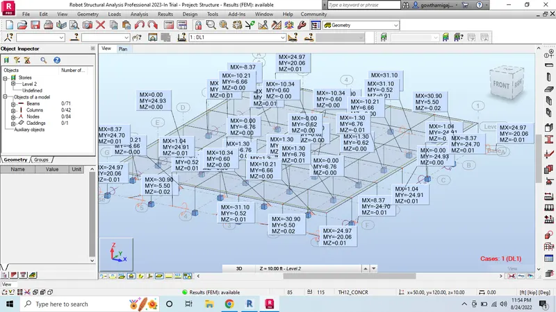
Result:
6. Aim: To analyse the energy and to consider it while modeling in revit.
Introduction: To analyse the energy and to consider it while modeling in revit.
Procedure:
General Principles:
- Calculation of heat loss and gain to the buildings and heating and cooling loads imposed upon the building systems.
- Then calculation of energy addition and extraction to meet the posibility varying the temparature and numeric criteria.
- Then determination of fuel requirement of primay equipment in the attempt to supply the energy of HVAC system.
- It evaluates the most of the equipment fuel requirement, electricity, labour and retrofic components against the alternative of investing money.
- Energy simulations can help in analysing the moment of energy in and out and through out the volumes in the building models.
- This information can help designers to make better inform cost effective decisions that include the performance that reduces the environmental impacts of the building.
Factors of sustainability to improve the quality of your design:-
- The sustainable design is intended to completely eliminate the negative environmental impacts through out the design process.
- This process can applied across all the fields of design such as design of the buildings.
- A sustainable design will improve the quality of design to lower the energy and water consumption through the entire life cycle.
- Then it minimize the impact on climate change by reducing the green house gas emission through the carbon utilising uilities.
- In resource through consumption limit free
- Then it looks for incoporate of the biometric priciples wherever possible.
- Then it gives preference to non toxic materials.
- Finally it improves the quality and suitability of the price.