Drafting of various geometries using Chamfer, Fillet tool in AutoCad
Aim: To design the given drawings in the attachment using commands in Autocad.
Introduction: By using Autocad software, we have to design the drawings given in the attachment.
Procedure: There are some drawings given in the attachment and the procedure for the drawings are listed below.
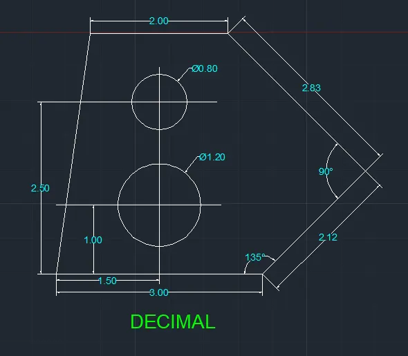
1. Procedure for the first drawing by using the units as Decimal.
- First we need to take the line command and draw the line about the length of 3.0 towards X-direction.
- Then from the last point take the angle of about 45deg towards 1st cordinate by using any coordinate method.
- And draw the line of 2.12 distance at an angle of about 45deg.
- Again take the angle of about 45deg towards negative X-direction at a distance of about 2.83
- Then the angle of the two points should be 90deg.
- From the last point, draw the line of about 2.0 distance towards negative X-direction.
- Then join the last point and first point.
- Finally mention the dimensions to each and every line and angle should be shown by using dimangle command.
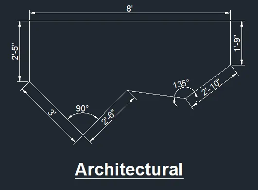
2. Procedure for the second drawing by using the units as Architectural.
- In this Architectural, Units should be in Feet and inches in the fraction values, But we have to take least measurement as inches.
- Take the first line at a distance of 8' from the starting point.
- Then from that point take 2'5" distance towards negative y-direction side.
- From that point, take the rectangular coordinate method and the angle should be 45deg.
- Draw the line of about 3' at an angle 45deg, and another line at an angle 45deg with distance 2'6".
- Then the toal angle of the two points should be 90deg.
- Now from another side of the line take the distance of about 1'9" at an angle of about 135deg.
- Then by using a horizantal line, draw the line between the last 2 points.
- Finally, mention the dimensions and angle of every point.
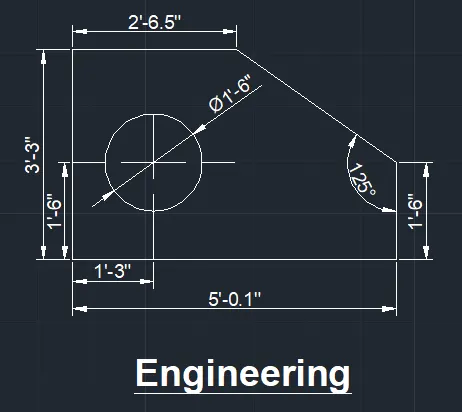
3. Procedure for the Third drawing by using the units as Engineering.
- In this Engineering, Units should be in Feet and inches and least units should be taken as inches.
- First we have to take the line at a distance of 2'6.5" and draw the line.
- Then to the Negative Y-direction side, take the line at a distance of 3'3" and draw the line.
- Now towards the positive X-direction side, draw the line at a distance of about 5'0.1".
- Now again draw the line of about 1'6" distance towards Y-direction side.
- Now join the first and last point of the line at an angle of about 125deg.
- Again take the offset at a distance of about 1'3" to the X-direction side, and 1'6" to the Y-direction side.
- Then draw the circle at a diamter of about 1'6".
- Then mention all the dimensions, angle and diameter to the circle as shown in the drawing.
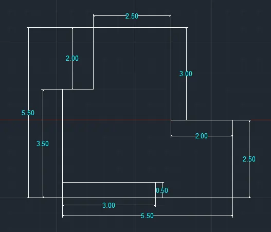
4. Procedure for the Fourth drawing by using the units as Decimal.
- Take the line command and draw the line at a distance of about 3.0 towards X-direction as shown in the drawing.
- From that take the 0.5 distance about Y-direction and again 2.5 distance to the X-direction side.
- Then draw the line again to Y-direction side of about 2.5 and to the Negative X-direction side at a distance of about 2.0.
- From that point again to the positive Y-direction side, draw the line of about 3.0 distance by calculating the dimensions given on the other side.
- Next take the line of about 2.5 distance towards negative X-direction and draw the line.
- From that point take the line of about 2.0 distance to Negative Y-direction and draw a line of about 0.5 distance by calculating the distance from the other side given.
- Then draw the another line about 3.5 distance to the negative X-direction side and close te line to the first point.
- Mention all the dimensions given in the drawing as shown in the attachment.
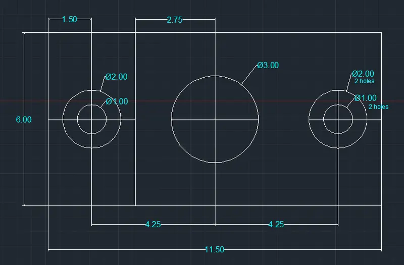
5. Procedure for the Fifth drawing by using the units as Decimal.
- First take the outside line dimensions as 11.50 at X-direction side and draw the line.
- Then from that point take another line of about 6.0 distance at Y-direction and draw the line.
- Then draw another line of about 11.50 distance and close the line to the starting point of the line.
- Now we have to draw the inside circles of the rectangle.
- Take offset command and draw the line of about 1.5 distance towards X-direction side and 3.0 distance towards X-direction side.
- By joining the above 2 points, take the centre point and draw the circle at a diamter of 2.0 and 1.0 from the centre points.
- Draw the 2 circle on both sides of the rectangle by using same procedure.
- Now, from the centre point of the circle, take the offset distance of about 4.25 from both side of the rectangle.
- Again draw the circle from the centre point at a diameter of about 3.0
- Now mention all the distances and diameters of the circles as shown in the drawing.
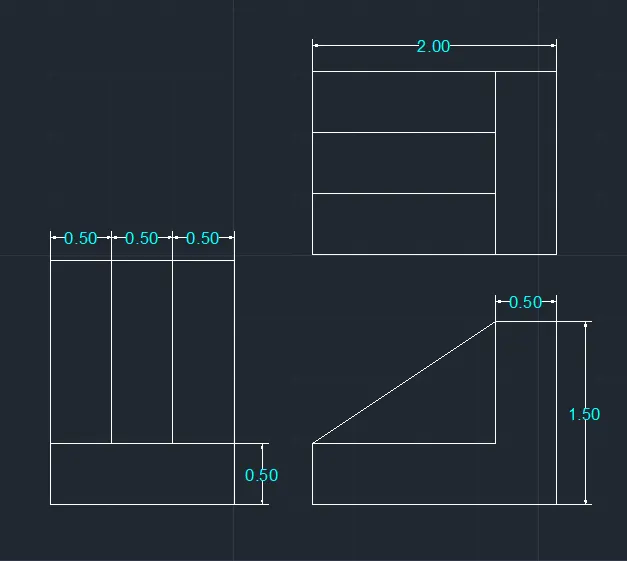
6. Procedure for the Sixth drawing.
- Take the line command, and add the dimensions properly and draw the line along X-Direction at a distance of 1.5
- Then take the distance as 0.5 towards Y-direction and 1.5 towards X-direction and close the line.
- Now, from the one end point draw the line at a distance of 1.5 towards Y-direction.
- Then draw again 1.5 towards Negative X-direction and close the line.
- Now from one end take the offset distance as 0.5 and divide the line into three and close at one end.
- Then with this, draw right side drawing by taking 2.0 distance in the X-direction.
- Then draw the line at a distance of 1.5 towards Y-direction.
- And draw at a distance of 0.5 line and close the line to the other end of the starting point.
- With this drawing, again take the points and draw to the top view of the drawing by taking the points.
- Or you can rotate the first drawing to the left side of the drawing.
- Now mention the dimenstions to all the points as shown in the drawing.
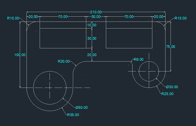
7. Procedure for the Seventh drawing.
- First take the corcle and draw the circle at a diameter of 50 and another circle at a radius of 35.
- Take the centre of the circle and draw the line at a distance of 100.
- From the point take another line at a distance of 210.
- Now do the fillet at the corner with radius 15.
- Now do the offset at a distance of 10 and 30 and 20 offset lines from the top line.
- Draw the rectangle at a distance of 70 length and 30 width.
- Do the mirror of the same object to the other side with the same dimensions.
- Now at the bottom side of the line draw the line and do the fillet at a radius of 6.
- Draw the another circle of radius 25 and another circle of diameter 30.
- Take the centre point of the circles and dra the line towards Y-direction at a distance of 75.
- Now give the dimensions to all the points and diameter and radius to all the circles.
8. Procedure for the Eighth drawing.
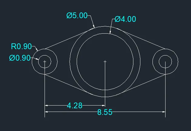
- First draw the 2 circles at a diameter of 4 and at a diameter of 5.
- Take the centre point of the circle and draw the reference line.
- Now from the line take the distance of about 8.5 line.
- Again at the both ends of the line draw the circles at a radius of 0.9 and diameter 0.9
- Now join the circles using lines or arc command on both sides of the circles as shown in the drawing.
- Mention all the dimension to the lines and circles.
9.Procedure for the Nineth drawing.
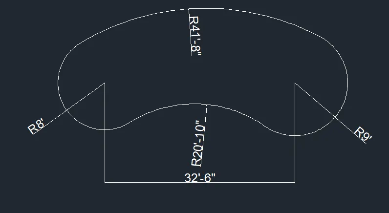
- By using the circle with radius we have to draw this drawing.
- First take the circle with radius 8' at one side and on the another side take another circle at a distance of 32'6" and radius 9'.
- Now by using tan tan radius at the circle command draw another circles at a radius by subtracting the dimension from top circle radius.
- Again take the circle at a radius of 41'8" and draw the circle at the center to the top of the drawing portion.
- Now by using trim command trim all the unwanted portions.
- Finally mention all the dimensions with radius of the circle.
10. Procedure for the Tenth drawing.
- In this drawing, We have to assume our own dimensions.
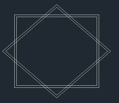
- Draw the rectangle with some dimension by assuming.
- Do the offset to the rectangle with some distance.
- Now copy the rectangle and rotate at some angle to the rectangle.
- No need to mension dimensions in this drawing.
11. Procedure for the Eleventh drawing.
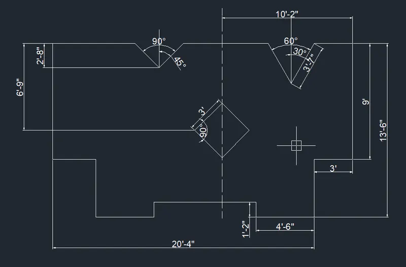
- Take the line command and draw the line at a distance of about 20'4".
- Now draw the line 4'6" and another line at 3' towards Y-direction.
- Again draw the line by calculating the dimensions and draw the lines.
- Now draw another line at a distance of 9' and draw another line at Negative X-direction.
- Now by using coordinate method, take the angle and distance as 3'7" and draw the lines.
- Angle at both sides should be 90deg as shown in the given drawing.
- In the same way, by taking angle and line distance draw the same lines in the opposite side.
- Now by calculating all the dimensions close the lines by using line command.
- Mention all the dimensions clearly as shown in the drawing.
Result:
For all the above procedure drawings, result drawings are listed below.
1.
2.
3.
4.
5.
6.
7.
8.
9.
10
11.