Creating a Floor plan, Footing detail and Isometric view using AutoCad
Aim: To design the given drawings given in the attachement.
Introduction: The given drawings in the attachement are designed using commands in the Autocad.
Procedure:
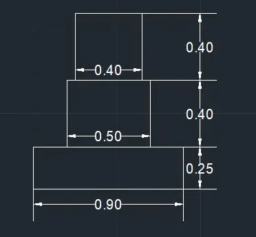
A. Procedure for C.S. of Load Bearing wall over spread Footing:-
- First we have to take the dimension from any part of the drawing.
- Let's take first point as 0.9, and using the line command we have to draw 0.9 dim line towards X-direction.
- Then from the ending point, 0.25 distance towards Y-direction and complete the rectangle by using given dimensions.
- Now from the line of 0.9, leave 0.2 on both sides and draw the line of 0.5 with the height of 0.4 and close the line on other side.
- Again leave 0.5 distance on both sides of 0.5 line, and draw the line using line command with the height of 0.4 and close on other side.
- By repeating the same procedure, again take 0.5 distance of offset on both sides and draw the line of 0.3 and close the line on other side.
- From the last point, take 0.05 offset line and close the line using line command on both sides as shown below.
-
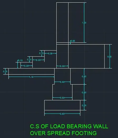
- Again from the last point, take 1.0 distance line form the last point and close the line on both sides.
- Next form the point of 0.3 line, draw the line towards Negative X- direction side with a distance of 1.15 and height of 0.15.
- By leaving 0.3 distance from the end point, again draw the line of 0.3 distance up to 3 times till the first line meets.
- On other side of positive X-direction, draw the line of some distance with the height of 0.60 from the 0.3 line and close the line to other side of the line.
- Finally give the dimensions to each line in the drawing using dal command or in the tool bar or from the menu bar.
- Adjust the dimension line and text to proper height thet looks neat to the drawing.
- At the bottom of the drawing, mention the name of the drawing using Mtext command.
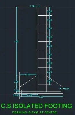
B. Procedure for C.S. Isolated Footing:
- First we need to draw outside line. Let's take the first point form the dimension of 1.0 and draw the line using line command.
- Draw the line towards Y-direction with the height of 0.15 distance line on both ends of the line.
- Next take offset distance of 0.04 line on both sides of the 0.15 distance line.
- Now draw the line using rectangular coordinate method of distance in X-direction 0.38 and in Y-direction of 0.25 line.
- From the last point draw the line using line command, with the height of 1.6 distance towards Y-direction on bothe end points of the line.
- Close the line at the last point of 1.6 line.
- From the line take 0.04 distance offset line inside of the line.
- Take offset of 0.2 line from the top of the line to the bottom of line excluidng 0.04 distance offset from starting line point in X-direction.
- Next take the offset diatnce of 0.04 on both sides of the starting line in Y-direction.
- Join all the lines as shown in the drawing using line command.
- Give the dimensions using dimension tool from the menu bar to all the points as shown in the drawing.
- Mention the name of the drawing to the bottom side using text command.
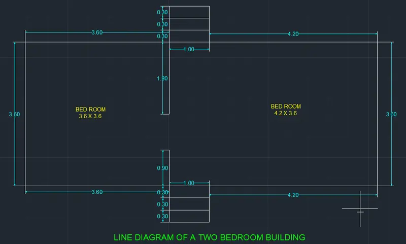
C. Procedure for Line diagram of a Two Bedroom Building:-
- Take the line command and draw the line at a distance of 3.6 towards positive X-direction.
- And from then 0.3 line towards Negative Y-direction for upto 3 times and draw the line of 1.0 distance line towards positive X-direction and draw the line of 0.3 distance line to the Y-direction.
- From the last point, draw the line at a distance of 4.2 towards positive X-direction.
- Now from the both end points of the line, we have to mirror the previous line at a distance of 3.6 towards Positive Y-direction and source object should be yes.
- Then We will get outside line of the drawing.
- From that we have to divide the Room for Bed room at a distance of 3.6 using loffset command.
- In that line we have to trim the line for the Door portion at a given distance as shown in the attachment.
- The remaining portion should be shown as Living.
- For both the rooms, Text should be shown by using Mtext command and the room simensions shoould be clearly shown with room name.
- Finally all the dimensions should be shown clearly and Name should be mentioned.
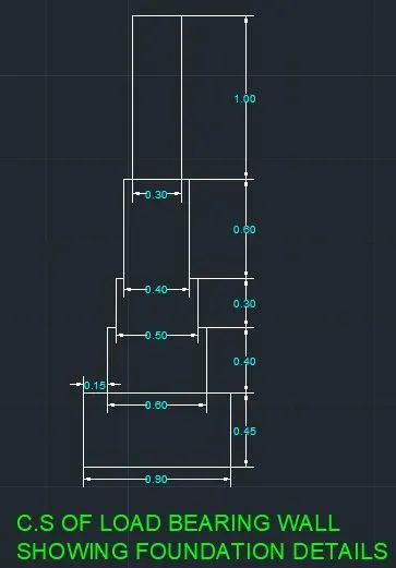
D. Procedure for C.S of Load bearing wall showing Foundation details:
- Draw the line of 0.9 distance line towards positive X-direction using line command.
- Take the 0.45 distance line on both end points of the last line towards positive Y-direction.
- From that 2 lines, leave 0.15 distance on both sides and draw the line at the remaining disatnec line as 0.6.
- Repeat the same procedure by leaving the 0.05 distance on both ends and draw the line at a distance of 0.5 line using line command.
- Next to that, again leave 0.5 distance offset on both ends and draw the line of 0.4 distance using line command.
- Using the Same process, draw the line of 0.3 distance line, at a height of 0.6 and draw the line using line command.
- from that draw the line at a height of 1.0 distance and 0.3 length line and close the line.
- Finally mention all the dimensions to the each point as shown in the drawing and name should be mentioned at bottom of the drawing.
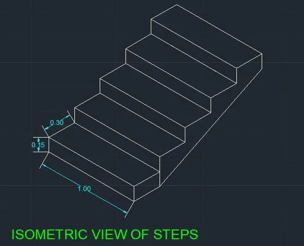
E. Isometric view of Staircase:
- For this Isometric view, we have to change the setiings by using command.
- Type ds in the command box and change the snap to view Isometric type.
- Then the cursor direction will get changed.
- The starting point should be taken towards Isometric top view at a distance of 1.0 by using line command.
- From that point draw the another line of 0.3 distance.
- Next cahnge the direction of Isometric view to right side direction and draw the line of 0.3 distance line.
- And draw the another line towards down direction at a distance of 1.0 line and close the line to the starting point.
- In this Isometric drawing, main condition is Ortho should be On.
- Now Copy all the drawn points and paste at the top corner of the point upto 5 times as shown in the drawing.
- Now at the X-direction close the steps using line command close all the points.
- Mention the dimensions to all the points using command in tool bar and show the mention the name to the drawing using Text command.
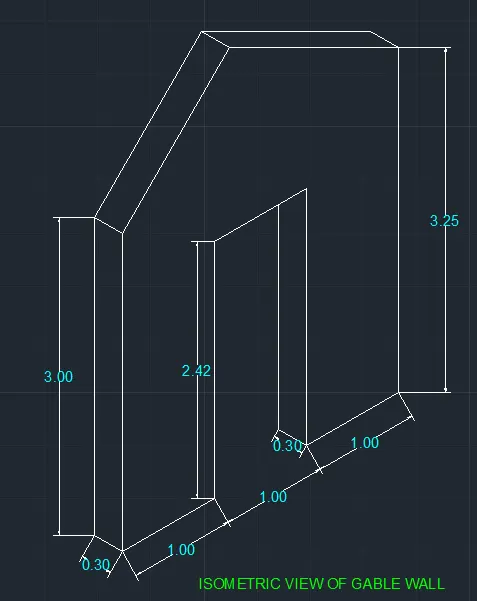
F. Isometric view of Gable Wall:-
- Maintain the Same Isometric settings to the drawing and Ortho should be on through out the drawing.
- Draw the line towards left direction at a distance of 1.0 using line command and 0.3 to the top of the left view.
- Change the Isometric view and draw the line to upwards of the right direction at a distance of 3.0 and 0.3 to the another line.
- Now close the line to the starting point of the line.
- From the starting line, draw the line towards right side of the upward direction at a distance of 2.0, and 1.0 to the right side and draw the lines.
- Now change the Isometric diection to bottom, and draw the line to the bottom side of the starting portion.
- From that again draw the line towards right side by changing isometric view to the right side and draw the line at a distanec of 1.0 using line command.
- Now again change the direction of Isometric to the right side and draw the line to the top at a distance of 3.25.
- Now we got the 2 end points of the line, Now by using Isometric view draw the lines, as shown shown in the drawing.
- Finally mention all the dimensions for every point as shown in the attched drawing.
Result:
A. Drawing for the C.S of load bearing wall over spread footing:
B. Drawing for the C.S Isolated Footing:-
C. Line diagram of a two bedroom building:-
D. C.S of load bearing wall showing Foundation details:
E. Isometric view of Steps:
F. Isometric view of Gable wall: