Structural analysis of a buidling using Robot Structural Analysis
1Q]
HVAC: -
Heating, ventilation, and air conditioning (HVAC) system is designed to achieve the environmental requirements of the comfort of occupants and a process.
It is a technology of indoor environmental comfort.
The main purpose of HVAC system is to satisfy the thermal comfort of occupants by adjust and changing the outdoor air conditions to the desired conditions of occupied buildings.
Depending on outdoor conditions, the outdoor air is drawn into the buildings and heated or cooled before it is distributed into the occupied spaces, then it is exhausted to the ambient air or reused in the system.
ESSENTIALS IN BUILDING MODELLING: -
- HVAC systems control the overall climate in the building. They also make the proper adjustments whenever we experience changes in outdoor temperature.
- Having a comfortable office climate increases the level of productivity and increases morale amongst the workers and employees
- Having a proper HVAC system installed is guaranteed to make your employees happy, hence, giving you better work results in return.
- HVAC systems not only regulate the temperature inside the building, they also improve the quality of air. The quality of air pertains to humidity, and a typical HVAC system will reduce the amount of humidity in the air.
- Proper HVAC systems are a worthy investment for any business or building owner because it gives you energy savings.
- Building & Equipment Durability.
- Maintaining pressurization between hazardous and non-hazardous areas.
- Increase Life & Health.
- Dilution and removal of potentially hazardous concentrations of flammable/toxic gaseous mixtures in hazardous areas.
- Filtration of dust, chemical contaminants, and odours through chemical and carbon-activated filters.
2Q]
AIM: -
Design HVAC system for each floor the model created in Challenge 7
Include the following elements in the HVAC system
Distribution centre
Collector
Ducts
Blower
PROCEDURE: -
Open Revit
Open new project with Mechanical template
Type VG
Visibility Graphics dialogue box opens.
Select SITE and Expand the list
Tick on Project base Point
Click on Apply and Press OK
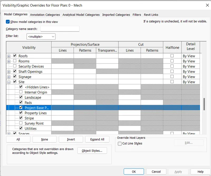
Base point appears on the model space.
Click on INSERT TAB
Go to LINK panel
Choose Link Revit tool
Import/Link RVT dialogue box opens
Select the Architectural File of challenge 7
Click on OPEN
Architectural File is imported to the Structural File.
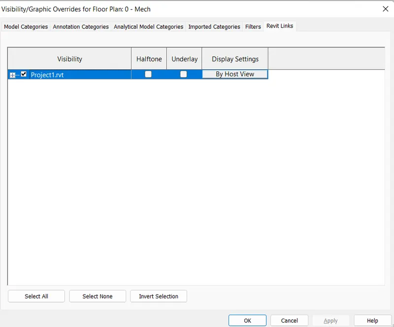
Now we have to copy these Gridlines to the structural file.
For that, Select COLLABORATE TAB
Go to Coordinate panel
Click on Copy/Monitor
Choose Select Link from the dropdown list
Click on the Link on the model space
Select COPY tool in the Ribbon tab
Tick on Multiple option
Select all the Levels in the Model space which are imported from the Architecture file.
Click on Finish then Click on COPY/MONITOR in the Ribbon tab.
Click on finish icon.
Now, The Levels are copied to the Mechanical File.
Select Systems Tab
Choose AIR TERMINAL tool
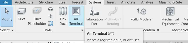
Go to Properties Browser
Select appropriate Air Terminal
We selected Supply diffuser type
Elevation: 2600
Press APPLY
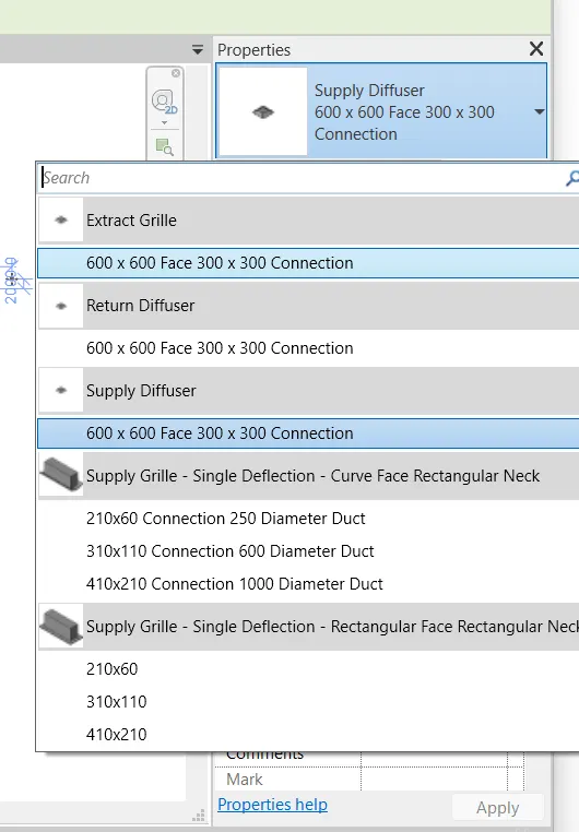
Place the Air terminals at the required positions
Select Systems Tab
Choose MECHANICAL EQUIPMENT tool
Go to Properties Browser
Select appropriate ELEMENT
We selected Air Handling unit horizontal
Press APPLY
place the component at desire position
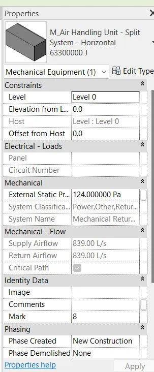
Select the Air supplier Air terminals and Mechanical Equipment

Choose Duct tool from the Modify Tab
Create Duct System dialogue box opens
Change the System name if required
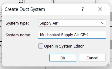
Press OK
After creating the Duct system
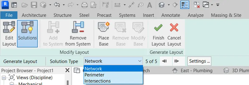
Choose Generate Layout tool from DUCT SYSTEMS TAB

We get all available options to place the duct
In our case we got total 5 options to place duct.
After selecting proper duct system, press Finish Layout option
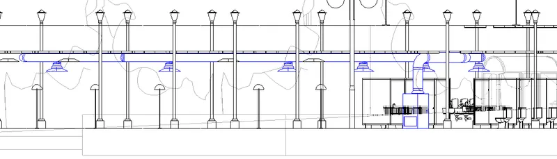
Repeat the same procedure to place Return diffuser
Select Systems Tab
Choose AIR TERMINAL tool
Go to Properties Browser
Select appropriate Air Terminal
We selected Return diffuser type
Elevation: 2600
Press APPLY
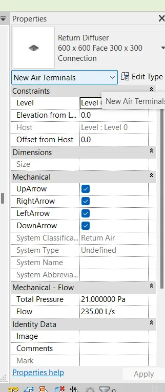
Place the Air terminals at the required positions
Select Systems Tab
Choose MECHANICAL EQUIPMENT tool
Go to Properties Browser
Select appropriate ELEMENT
We selected Air Handling unit horizontal
Press APPLY
place the component at desire position
Select the Air supplier Air terminals and Mechanical Equipment
Choose Duct tool from the Modify Tab
Create Duct System dialogue box opens
Change the System name if required
Press OK
After creating the Duct system
Choose Generate Layout tool from DUCT SYSTEMS TAB
We get all available options to place the duct
In our case we got total 5 options to place duct.
After selecting proper duct system, press Finish Layout option
Select all the HVAC components
Click on MODIFY TAB
Choose Copy to Clipboard tool
Click on PASTE tool
Select Aligned to Selected levels from the dropdown list
Select all the levels
press ok
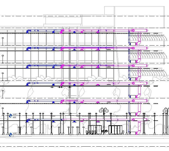
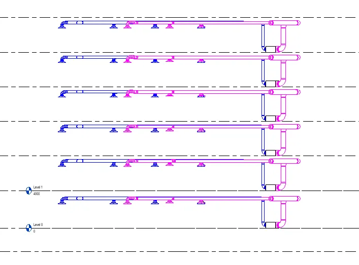
RESULT: -
We designed HVAC system for each floor the model created in Challenge 7
Included the following elements in the HVAC system
Distribution centre
Collector
Ducts
Blower
3Q]
Open the Revit software.
Go to the Analysis tab and check whether the robot structural analysis is enabled in our software or not
If not, available we need to download if from Autodesk store
Open Google
Type Robot Structural Analysis Professional 2023

Open the link marked in the screenshot
Open the products Tab
Search for Robot Structural Analysis software
Download the required version
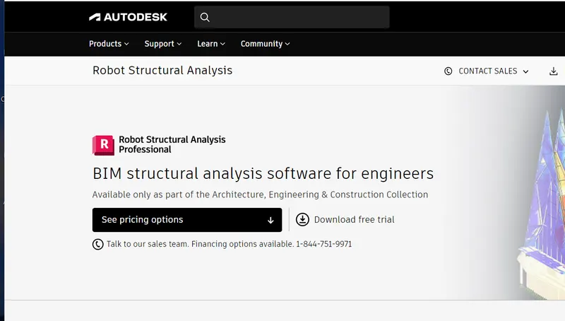
Install the software
Open Revit and check whether the Robot Analysis icon is available in Analyse Tab

In our case the software installed succesfully and icon is created in Analyse Tab in Revit.
4Q]
The process to determine the response or behaviour of a structure under some specified loads or combination of loads is known as Structural analysis.
Response means to find out support reactions, bending moment, rotation, stresses, strains, shear force, and deflection that, the particular member would undergo due to the application of different types of loads.
Analysis of a structure involves its study from the viewpoint of its strength, stiffness, stability, and vibration.
Structural analysis is a comprehensive determination to assure that the deformations due to load in a structure will be satisfactory and lower than the permissible limits, and failure of structure will never occur.
Before the design, we have to determine the behaviour of structure under different load conditions.
The structure is analysed for different load combination like gravity load, live load, wind load, earthquake load apart from effects of nature and environment etc.
The objective of analysis of a structure from the viewpoint of its strength is calculating internal forces, which will arise in all members of a structure as a result of external exposures.
The objective of analysis of stability of a structure is to determine the loads on a structure, which leads to presence of new forms of equilibrium.
The objective of analysis of a structure from the viewpoint of its stiffness is the determination of the displacements at specified points of a structure as a result of external exposures. The objective of analysis of a structure from the viewpoint of its vibration is to determine the frequencies and correlative shapes of the vibration.
These data are necessary for analysis of the forced vibration caused by loads like earthquake, wind etc.
Yes, Design affect modelling.
The structure is an essential element, defines the shape of the architectural shape and space.
Structural designing provides all the crucial information about foundations, walls, floors, roof types, steep beams, material quality, and more to ensure that the structure is built to be safe and sound.
This helps to ensure that the new or existing structure meets up all the necessary safety criteria and design codes.
Structural designing is also interlinked with ensuring the efficient use of construction materials and resources. Civil engineers have to determine the optimal material grade to ensure safety and operational use of the structures without any unnecessary costs.
5Q]
(A)
Boundary conditions are constraints necessary for the solution of a boundary value problem.
A boundary value problem is a differential equation (or system of differential equations) to be solved in a domain on whose boundary a set of conditions is known. It is opposed to the “initial value problem”, in which only the conditions on one extreme of the interval are known.
- The material is homogenous and isotopic.
- The deformation on the plane remains too negligible, hence it remains plane even after bending.
- The axial deformation is too small to inflict any change in area of the beam.
- The internal forces, such as bending moments, shear forces, and normal and shear stresses, at any section of a member are in equilibrium with the effects of the external loads at that section.
- Sections perpendicular to the axis of bending, that are plane before bending remain plane after bending.
- It is assumed that perfect bonding exists between concrete and steel at the interface so that no slip can occur between the two materials. Hence, as the one deforms, so must the other.
- In view of the fact that the tensile strength of concrete is only a small fraction of its compressive strength, it is assumed that concrete is not capable of resisting any tension stress whatsoever.
Defining the boundary conditions in a model is one of the most important part of preparing an analysis model, irrespective of the software that you use. Supports are an essential part of building your model to ensure accurate and expected results. These are not to be ignored nor guessed as it can lead to your structure not behaving in the way you anticipated. To define supports you need to be aware about the support detailing in case of steel structures. For example, a support column in a steel structure can be pinned or fixed, depending upon the detailing adopted.
Boundary Conditions for Structural Analysis:
The following boundary conditions are assumed for different structures:
Free End
The free end of any structural element can be subjected to linear to rotational displacement due to action of load. But, there is no sort of reaction happening at this end.
Roller Support
At a roller support end, the member is free to move along the support and to rotate freely. It resists the movement of the member at the support in the direction perpendicular to the support.
Hinged Supports
At a hinged support as shown in figure below, the support restricts linear motion i.e. along X and Y direction. But it allows to rotate freely about the support i.e. about the point that is pinned.
Fixed Ends
A fixed end does not permit any linear or rotational movement. Hence, at the fixed end, the support develops both resisting force or reaction in X and Y direction and also resisting moment.
(B)
Floors must be capable of bearing loads applied to them. There are two main types of load - live loads and dead loads:
- Dead loads include the weight of the building materials themselves, and are static and permanent. The dead load value is determined by adding together the weight of all permanently installed materials.
- Live loads are imposed on the building and are temporary and dynamic, such as the weight of occupants, furniture or anything else that can be moved.
To determine the minimum design values for strength, live and dead loads are added together.
(C)
As per the combinations the main loads are classified in to below types
- Dead load
- Live load
- Seismic load
- Wind load
Load Combinations considered for the analysis:
Limit state of collapse:
1.5(DL + LL)
1.2(DL + LL + WL)
Limit state of Serviceability:
1.0(DL + LL)
1.0(DL) +0.8(LL + WL)
(D)
AIM: -
Create Analytical model in the Revit
Send the model to the Robot Structural Analysis
Perform the Analysis of the model
Report the following results:
Maximum moment in each Floor
Maximum displacement in each floor
Lateral displacement in building
PROCEDURE: -
Open Structural File of the model
Go to Project Browser
Double click on Level-1 Analytical
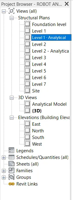
Click on ANALYSE TAB
Go to Structural Analytical Model panel
Choose member tool to draw columns.

Select Top point Definition tool fom the Analytical member panel to draw columns.

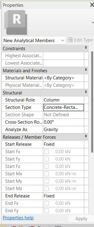
Go to Properties Browser
Change the data
Structural role: column
Structural Type: Concrete-Rectangular 300 x 450mm
Press APPLY
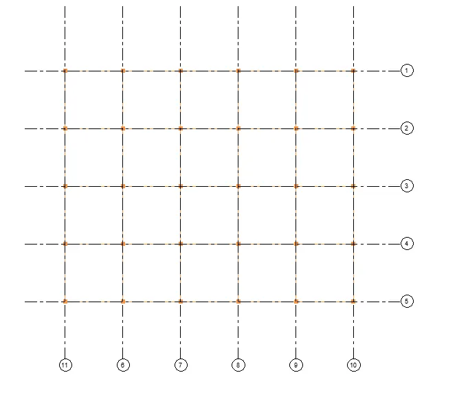
Draw columns in the model space on the grids.
Click on ANALYSE TAB
Go to Structural Analytical Model panel
Choose member tool to draw beams.
Select StartEnd point Definition tool fom the Analytical member panel to draw beams.

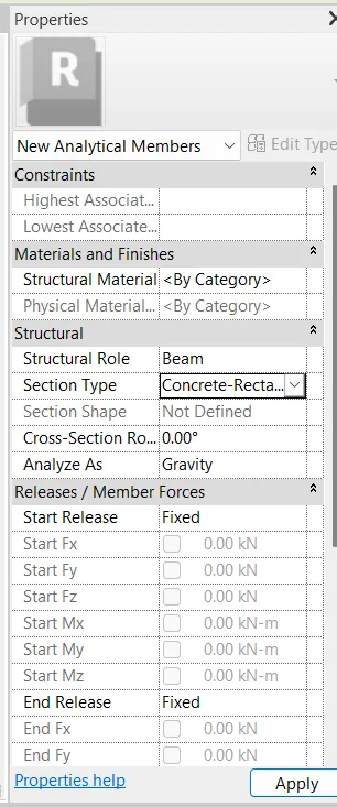
Go to Properties Browser
Change the data
Structural role: beam
Structural Type: Concrete-Rectangular 300 x 60mm
Press APPLY
Draw beams in the model space on the grids.
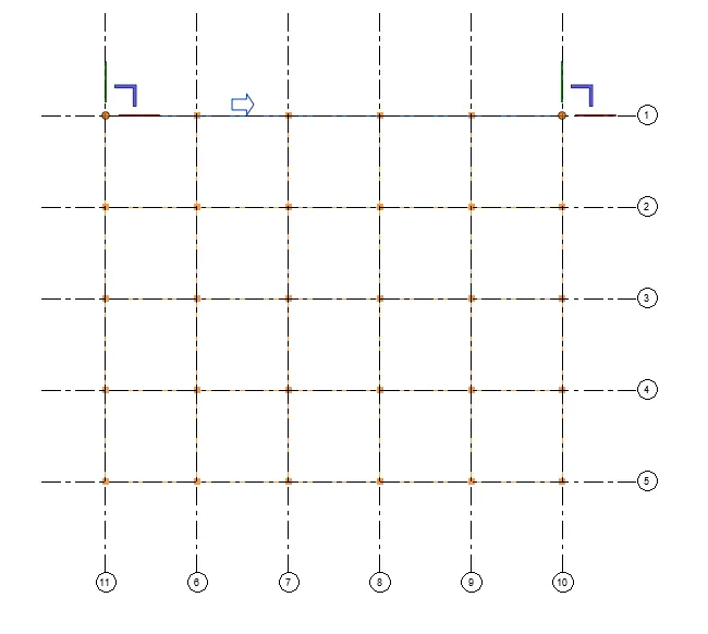
Click on ANALYSE TAB
Go to Structural Analytical Model panel
Choose Panel tool to draw Floors.
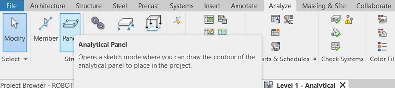
Select appropriate tools from the Draw panel to create Floor in the moedl space.

Floor is created in the model space
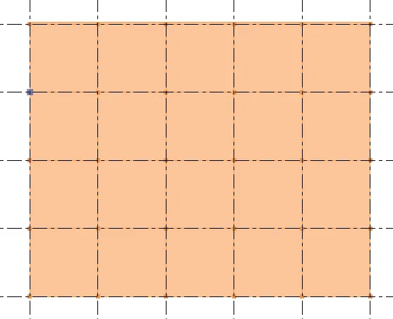
Now Assign loads to the model.
Select ANALYSE TAB
Go to Structural Analytical Model panel
Click on Loads

Choose Point Load
Go to Properties
Click on Edit Type
Change the data if required
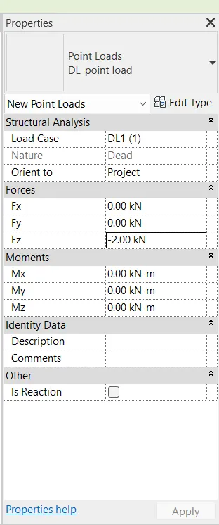
Name: DL-point load
Fz (load value) : -2 kN
Press APPLY
Place Point loads on the columns in the model space.
Select ANALYSE TAB
Go to Structural Analytical Model panel
Click on Loads

Select Line Load
Apply the loads on the beams
Go to Properties
Click on Edit Type
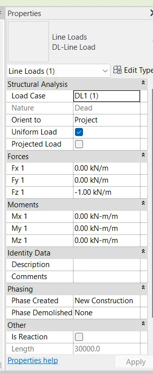
Change the data if required
Name: DL-Line load
Fz (load value) : -1 kN/m
Press APPLY
Select ANALYSE TAB
Go to Structural Analytical Model panel
Click on Loads
Select Area Load
Apply the loads on the Floor
Go to Properties
Click on Edit Type
Change the data if required
Name: DL-Area load
Fz (load value) : -1 kN/m
Press APPLY
Select ANALYSE TAB
Go to Structural Analytical Model panel
Click on Loads
Select Area Load
Apply the loads on the Floor
Go to Properties
Click on Edit Type
Change the data if required
Name: LL-Area load
Fz (load value) : -1 kN/m
Press APPLY
Create Load Combinations
Select ANALYSE TAB
Go to Structural Analytical Model panel
Click on Loads Combinations
Structural Settings dialogue box opens
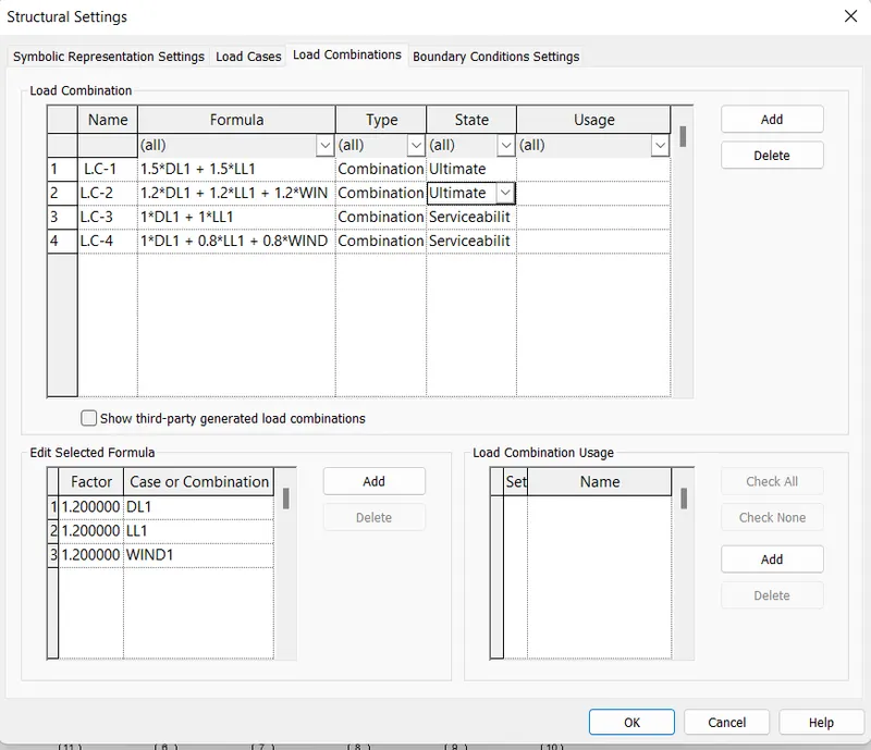
Press Add option
Add Combinations as per the code
Ultimate:
1.5(DL + LL)
1.2(DL+LL+WL)
Serviceability:
1.0(DL+LL)
1.0DL+0.8(LL+WL)
Press OK
Select all the loads created
Click on Modify Tab
Click on Copy to clipboard tool
paste to Aligned Slected levels.
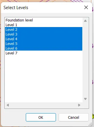
Select all the Levels
Press OK
Loads are applied to all Levels.
Create Boundary Conditions
Select ANALYSE TAB
Go to Structural Analytical Model panel
Click on Boundary conditions


Select Point option in Modify Tab
Select fixed option
Assign to all Columns at Footing.
Press OK
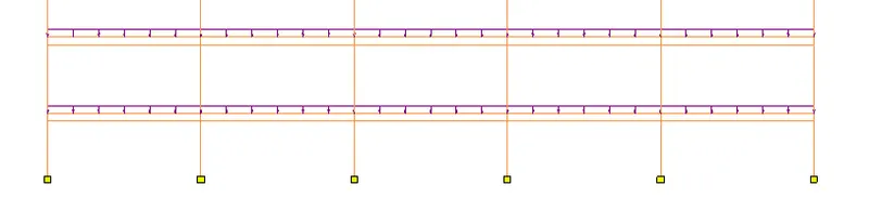
Create Analytical model to all levels
For this
Select ANALYSE tab
Go to Structural Analytical Model panel
Click on Analytical Automation

Analytical Automation dialogue box opens
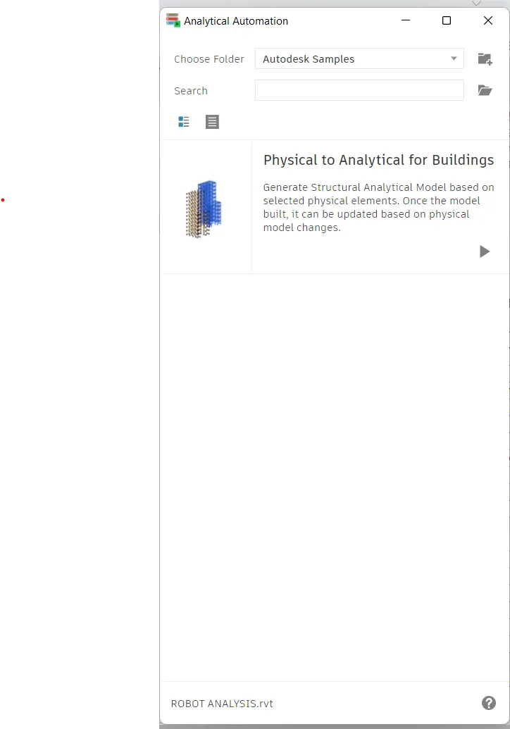
Click on play buttion
Select physical elements
For this open the 3D model in the model space
Select complete model
Press Run
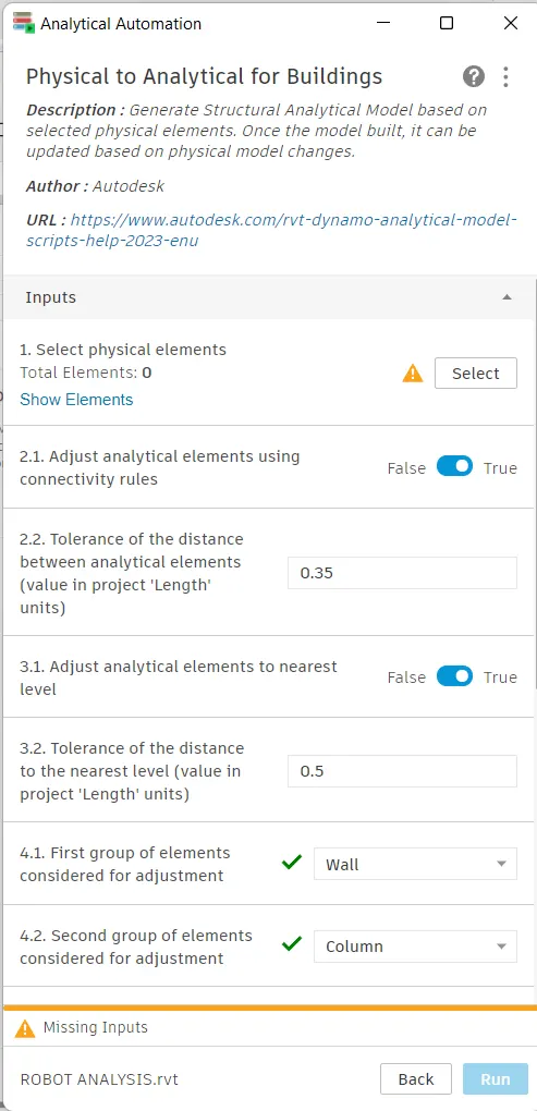
Analytical model is created for all levels
We created Analytical model
We applied Loads to each floor
We created load cases and Load combinations.
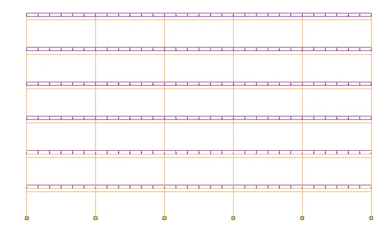
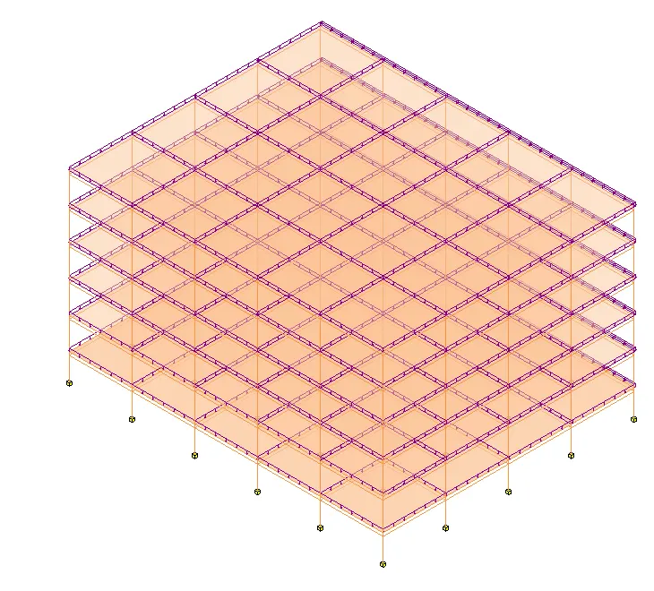
Send the model to Robot Structural Analysis.
Select ANALYSE TAB
Go to Structural Analysis panel
Click on Robot Structural Analysis
Select Robot Structural Analysis Link

Integration with Robot Structural Analysis dialogue box opens
Press OK
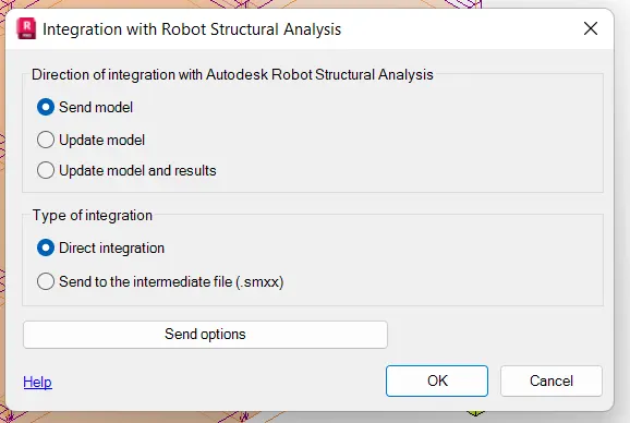
Now the model sent to Robot Structural Analysis software.
Robot Structural Analysis Professional software is opened.
Select Edit Tab
Choose Select all option from th dropdown list
Select Edit Tab
Choose Select all option from th dropdown list
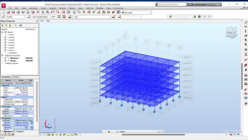
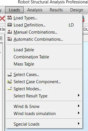
Select Loads Tab
Choose Load Definition option
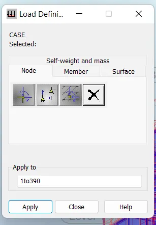
Load Definition dialogue box opens
Click on Menber
Press Apply and close
Select Loads Tab
Choose Load Combinition option from the dropdown list
Combinations dialogue box opens
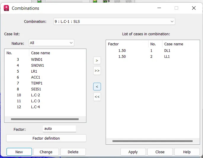
Choose the Load combination and Press APPLY.
Select ANALYSIS TAB
Choose Calculations option from the list
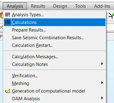
Calculations dialogue box opens
Static Analysis starts
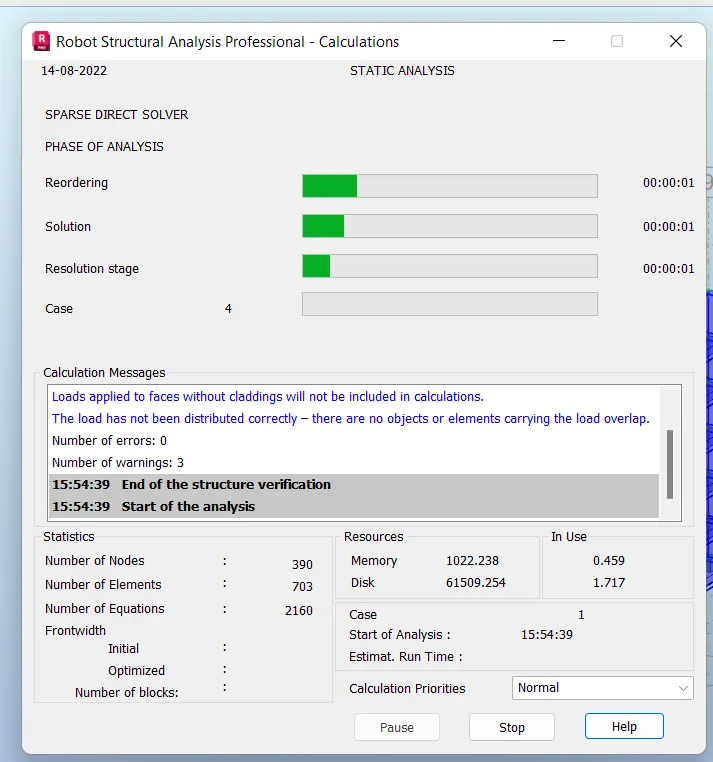
After completion of Analysis
Calculation message box appears on screen with details related to analysis.
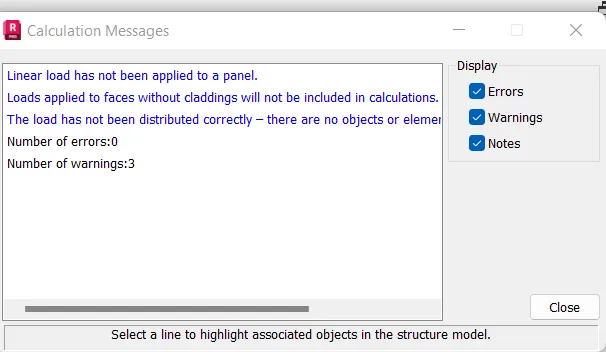
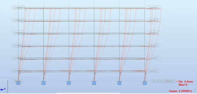
We have finished the Analysis using Robot Structural Aalysis Professional
RESULT: -
We created Analytical model
We assigned Loads
We assigned Boundary conditions
We created Load combinations
We analysed the structure using Robot Structural Analysis.
We calculated Maximum moment in each Floor
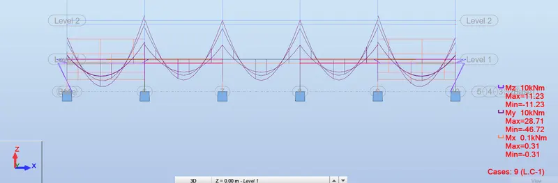
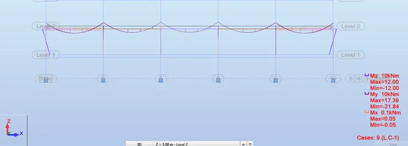
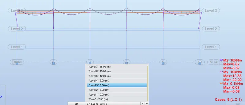
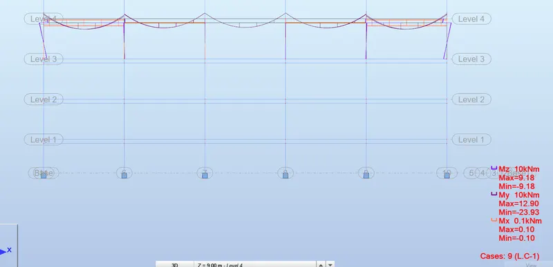
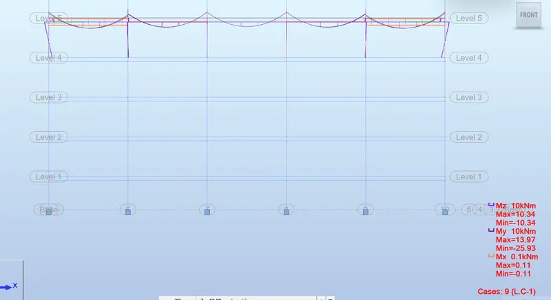
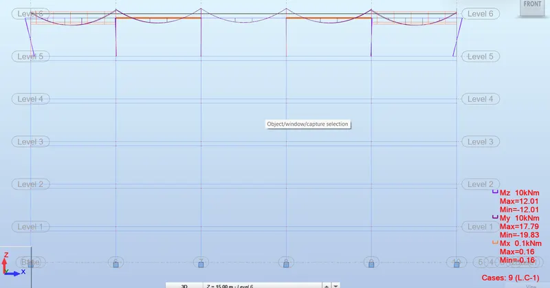
We calculated displacements in each Floor
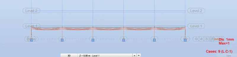
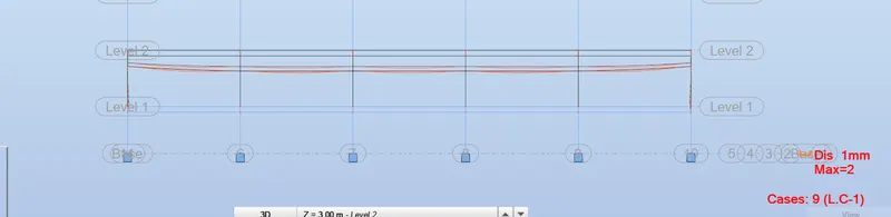
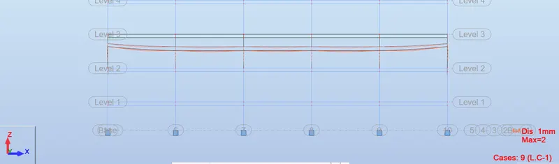
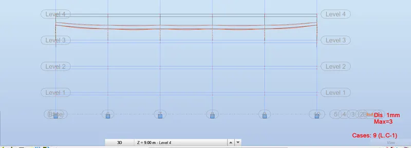
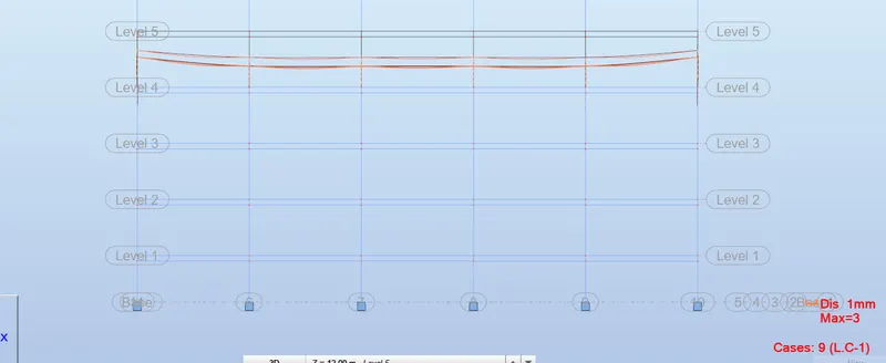
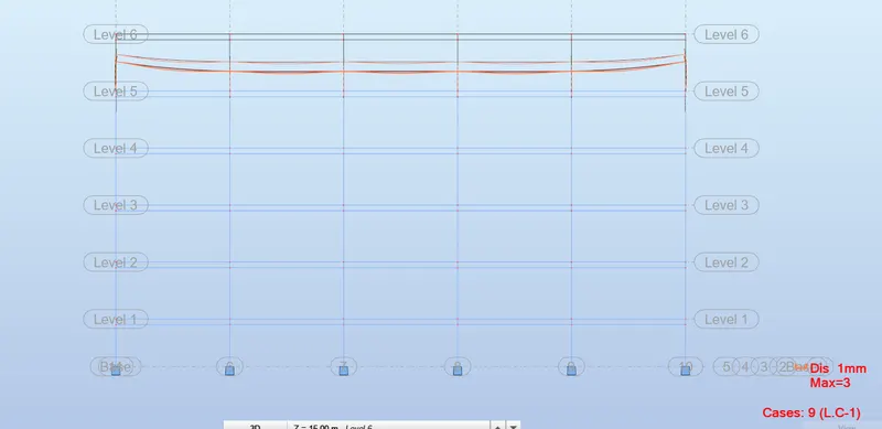
Lateral displacement in building for all Lateral Load Combinations.
E]
I think we need or have a better approach or idea in modelling structural members.
6Q]
Buildings demand energy in their life cycle right from its construction phase to demolition phase.
High energy consumptions may lead to serious environmental impacts like increase in the rate of global warming. Therefore, it is important to study the energy consumption of building at the conceptual stage
It includes the energy content of all the materials used in the building and technical installations, and energy incurred at the time of erection/construction and renovation of the building.
Operating energy is the energy required for maintaining comfort conditions and everyday maintenance of the buildings.
Energy usage analysis of buildings involves four principal steps.
First is the calculation of heat loss and gain to the building spaces and the heating and cooling loads imposed upon the building HVAC systems.
This calculation is carried out for a space temperature fixed in time and is commonly called the Loads calculation.
Second is the calculation of the energy addition and extraction actually to be supplied by the HVAC system in order to meet the possibly varying temperature set-points and humidity criteria subject to the schedules of fans, boilers and chillers, and to outside air requirements. This calculation results in the demand for energy that is made on the primary energy sources of the building.
Third is the determination of the fuel requirements of primary equipment such as boilers and chillers, and of the' energy production of solar collectors, etc., in the attempt to supply the energy demand of the HVAC systems.
Fourth step evaluates the costs of equipment, fuel, electricity, labour and retrofit components against the alternative of investing the money in other ways.
FACTOR OF SUSTAINABILITY IMPROVE THE QUALITY OF THE DESIGN: -
Sustainable design seeks to reduce negative impacts on the environment, and the health and comfort of building occupants, thereby improving building performance. The basic objectives of sustainability are to reduce consumption of non-renewable resources, minimize waste, and create healthy, productive environments.
Sustainable design principles include the ability to:
- optimize site potential;
- minimize non-renewable energy consumption;
- use environmentally preferable products;
- protect and conserve water;
- enhance indoor environmental quality; and
- optimize operational and maintenance practices.
Utilizing a sustainable design philosophy encourages decisions at each phase of the design process that will reduce negative impacts on the environment and the health of the occupants, without compromising the bottom line. It is an integrated, holistic approach that encourages compromise and trade-offs. Such an integrated approach positively impacts all phases of a building's life-cycle, including design, construction, operation and decommissioning.