Structural analysis of a buidling using Robot Structural Analysis
1) What are HVAC systems? Why are they essential in the modeling of buildings
HVAC stands for Heating, Ventilation, and Air Conditioning. HVAC refers to the different systems used for moving air between indoor and outdoor areas, along with heating and cooling both residential and commercial buildings. They are the systems that keep you warm and cozy in the winter and feeling cool and fresh in the summer. They also are the systems that filter and clean indoor air to keep you healthy and maintain humidity levels at optimal comfort levels.
The purpose of an HVAC system is more than just warming or cooling a space. Instead, it serves to improve indoor air quality and provide comfort for everyone inside a building. While there are several different types of HVAC systems, they all begin with the same essentials.
First, there is a source of fresh air intake from the outside or from within the home. This process is called ventilation, and it happens in two different ways. Natural ventilation is present in most homes and refers to the way air typically moves in and out through windows, doors, vents, and other openings. This exchange of air is necessary to replenish oxygen, and to remove odors, carbon dioxide, and excessive moisture.
Mechanical ventilation uses a mechanical system ‐ the V in HVAC ‐ to move air in and out. In the past, there was plenty of natural ventilation in most homes from gaps and cracks in the construction along with opening and closing of doors. However, modern construction is creating homes that are far more tightly sealed so ventilation is becoming an increasingly important component in home HVAC systems. Once the air is brought in, it is drawn into an air handling unit where the work begins. Here, air is drawn through filters to remove dirt, dust, allergens, and other particles.
Next up, is comfort. Air is either sent to be heated or sent to be cooled and have excess humidity removed. Once the air is clean, fresh, and at a comfortable temperature, it is directed into the home. For central systems, this means moving through a network of ducts and registers to different rooms. For other systems, this usually means being directed right into the space.
The HVAC system modeling implies to the modeling of building, indoor, outdoor, and air handling unit (AHU) equipments. It is normally difficult for one HVAC system model to be completely comprehensive. Therefore, it is possible to divide the comprehensive model into submodels which may be appropriate in some instances. The key to any successful indoor thermal analysis or representation lies in the accuracy of the model of the indoor conditioned space within building and AHU equipments.
The simple hand-calculation methods were available to find out the cooling/heating load until the advent of computer simulation programs for the HVAC systems in the mid 1960s. The first simulation method attempted was to imitate physical conditions by treating the variable time as the independent [1]. Most of the earliest simulation methods were based on the white-box or mathematical (physical) models, which are preferred over other models such as the black-box and the gray-box models because they are easy to analyze even though they are more complex than others
2) From week 7 assignment, based on the building designed use the same Revit file to design a HVAC system for each floor to cover the topics included in the class.
a. Typical HVAC unit includes Distribution center
b. Collector
c. Ducts
d. Blower
AIM:
Design a HVAC system for each floor to cover the topics included in the class.
a. Typical HVAC unit includes Distribution center
b. Collector
c. Ducts
d. Blower
INTRODUCTION:
HVAC stands for Heating, Ventilation, and Air Conditioning. HVAC refers to the different systems used for moving air between indoor and outdoor areas, along with heating and cooling both residential and commercial buildings. They are the systems that keep you warm and cozy in the winter and feeling cool and fresh in the summer. They also are the systems that filter and clean indoor air to keep you healthy and maintain humidity levels at optimal comfort levels.
Collectors are used to generate electricity and provide low grade heating and cooling energy for buildings by using winter daytime solar radiation and summer night-time sky radiative cooling, respectively. The PCM is integrated into the building ceiling as a part of the ceiling insulation and at the same time, as a centralized thermal energy storage to temporally store low grade energy collected from the collectors.
Ducts are conduits or passages used in heating, ventilation, and air conditioning (HVAC) to deliver and remove air. The needed airflows include, for example, supply air, return air, and exhaust air.Ducts commonly also deliver ventilation air as part of the supply air. As such, air ducts are one method of ensuring acceptable indoor air quality as well as thermal comfort.
HVAC fans and blowers are used to move air through heating, ventilating, and air conditioning (HVAC) systems. They are an integral part of the air handling systems that bring or draw fresh air into buildings. HVAC fans and blowers can be mounted to an exterior wall (ventilation unit) or above the ceiling (plenum fan), or used as part of a ducted system (duct fan). The fan spins or the blower turns by means of an electric motor, thus creating unidirectional air flow. Often, the air is pre-heated or cooled.
PROCEDURE:
For HVAC Design:
- Open the revit software
- Select the mechanical template to work on
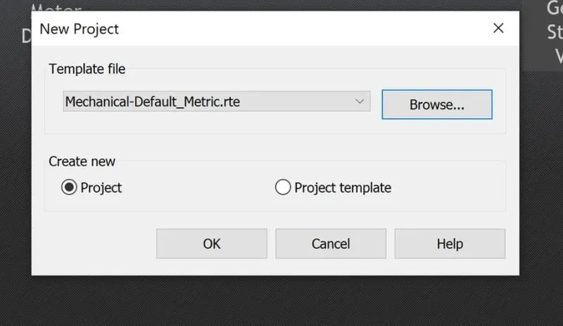
- Save the file
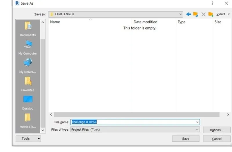
- Now go to the insert tool bar and select link revit option to link the file to the mechanical template
Click Insert tab>Link panel>Link Revit
In the Import/Link RVT dialog, select the model to link.
- Now select the file we want to link . Then press open and the desired file will be opened in the tab
- Now for the placement of the mechanical equipments go to the mechanical equipments , go to the systems toolbar and then select the aie terminals for the supplier and the returns
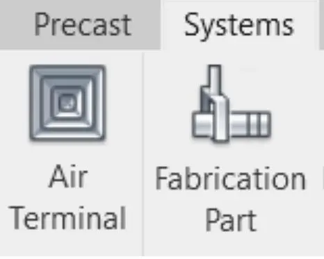
- Now adjust the supplier and returns to the ceiling as needed
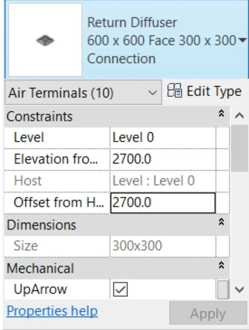
- Place the supplier difffusers as needed in place
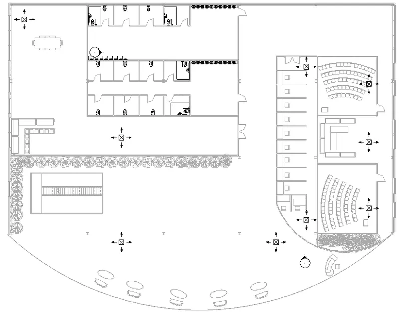
- Place return difffusers as needed in place
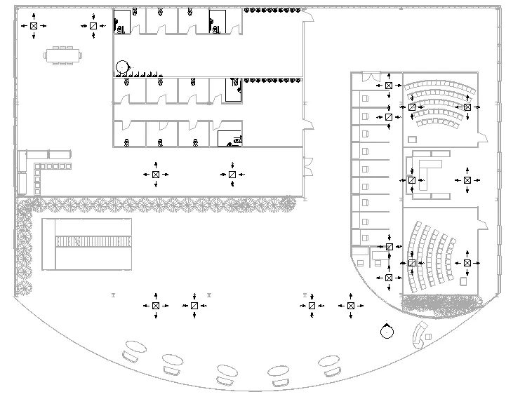
- Now add the air handling unit from the (SYSTEM> MECHANICAL EQUIPMENT > AIR HANDLING UNIT)
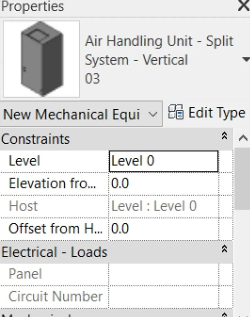
- Now adjust the air handling unit to the areas needed
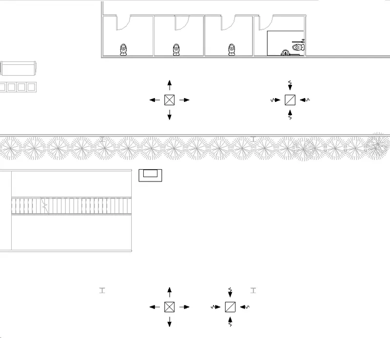
- Now for creating the connections select all the suppliers and air handling unit and then select duct option to create connection
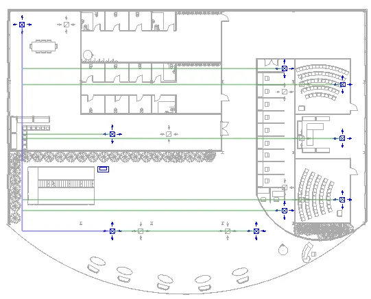
- Now do the same to the return valves and hence HVAC is created
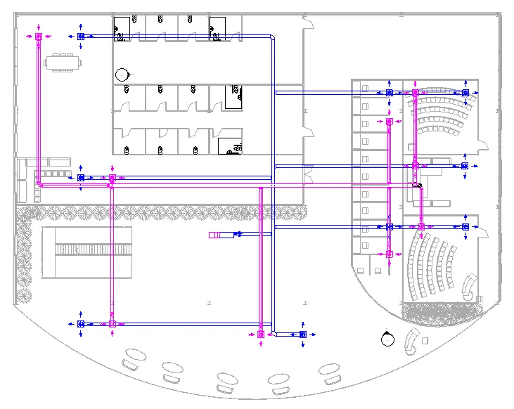
- Copy it to clipboard and paste it to all the assigned levels
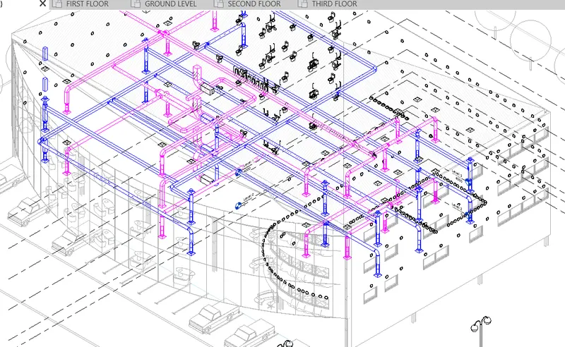
RESULT:
Typical HVAC unit includes Distribution center, Collector, Ducts and Blower are inserted as per question
3. Use the add-ins tab to load plug-ins for robot structural analysis to your Revit software
AIM:
To Use the add-ins tab to load plug-ins for robot structural analysis to your Revit software
INTRODUCTION:
Robot Structural Analysis Professional is structural load analysis software that verifies code compliance and uses BIM-integrated workflows to exchange data with Revit. It can help you to create more resilient, constructible designs that are accurate, coordinated, and connected to BIM.Robot Structural Analysis Professional is available only in the Architecture, Engineering & Construction Collection, an essential set of integrated Building Information Modeling (BIM) tools. Autodesk Robot Structural Analysis hosts a range of powerful FEM solvers enabling structural engineers to conduct complex calculations such as modal, harmonic, spectral, dynamic, non-linear, footfall analysis and many more.
Robot Structural Analysis Professional is a finite element analysis software suited for engineers who require a structural analysis solution that allows them to model, analyse and design a range of materials such as steel structures and concrete structures to Eurocodes, American codes and British standards amongst others.
This comprehensive structural engineering design software solution allows enhanced BIM operability both within the AEC collection and other software enabling engineers to iterate and optimise their designs with full communication between packages ultimately streamlining the design process and allowing traceability of design changes along the way.
Robot allows engineers to design their structural elements to many codes such as:
- Combinations: Eurocode 0, BS5950 and BS8110 (UK), other local standards (USA, France, Canada, Italy, etc.);
- Climatic loads: Eurocode 1 and other local standards (France, Romania, Italy, USA, Canada, etc.);
- Reinforced concrete design: Eurocode 2, BS8110 (UK), and other local standards (USA, Canada, France, Italy, etc.);
- Steel design: Eurocode 3, BS5950 (UK), and other local standards (USA, Canada, France, Italy, etc.);
- Timber design: Eurocode 5 and other local standards (France, Italy, etc.);
- Geotechnical design: Eurocode 7, BS8004 (UK), and other local standards (France);
- Seismic loads: Eurocode 8 and other local standards (France, Canada, USA, Italy, Romania, etc.).
PROCEDURE:
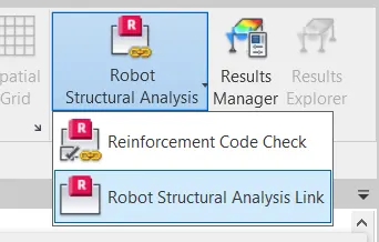
For the robot structural analysis software, go to the add ins tab
Now after searching the official autodesk website search for the robot structural analysis toolkit and also it should be the compatible version with the revit version
Now install it in PC
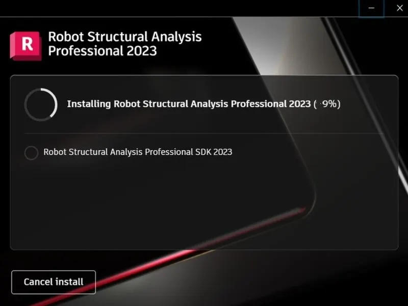
Hence the robot structural analysis will be automatically linked to the revit
Now see in the analysis tab to see if the robot structure analysis is linked or not
4.Why do we need to assess buildings/analyze while modeling elements? Does design affect modeling in anyways?
Structure is one of the important componenet of the building. During the preliminary structural design stage, a structure’s potential external load is estimated, and the size of the structure’s interconnected members are determined based on the estimated loads. Structural analysis establishes the relationship between a structural member’s expected external load and the structure’s corresponding developed internal stresses and displacements that occur within the member when in service. This is necessary to ensure that the structural members satisfy the safety and the serviceability requirements of the local building code and specifications of the area where the structure is located.
The structural framework is the skeleton of the building and any shortcoming n that will cause damage to the whole building.Consideration of the technical aspects of the construction stage is very important in highrise building analysis and design. If we consider the whole structure with a single model, it means that the whole structure is constructed at once.If we analyze the structure as one stage construction, actual stress distribution in the different stages of the construction is not count.For example, it considers the total settlement of the elements to generate stresses. Consider the beams connected with the shear wall and column having relative displacement due to the shortening. When one stage construction is considered the total shortening affects the elements and additional stresses are shown as per the stiffnesses.If we have done the construction stage analysis, it reduces the effect. The effect of the elastic shorting is only the shorting causes by column axial load form above levels. Similarly, other effects are also reduced considerably.
All the loads and load transfers are taken care by creating the structural framework
Analyzing the building is nothing but calulating forces and bending moments that occur when loads are applied
Revit enables us to calculate the forces , recreations , bending moments that occur when load is applied to the building using structural analyss option making work ay easier for the designers
Energy analysis is also an important aspect as it calculates the overall performance of buildings . Perform energy analysis on the building design through all stages, from the earliest conceptual phase through detailed design, to ensure that you are constantly working towards the most energy efficient building possible. Buildings demand energy in their life cycle right
from its construction phase to demolition phase. High energy consumptions may lead to serious environmental impacts like
increase in the rate of global warming. Therefore, it is important to study the energy consumption of building at the
conceptual stage. One of the recent method to evaluate energy consumption of buildings is Energy analysis using Building Information Modeling (BIM) tools –Autodesk Insight, BIM is an intelligent 3D model-based process that gives Engineers the
insight tools to more efficiently plan, design, construct, and manage buildings and infrastructure. BIM assist designers
assess different design alternatives at the conceptual stage of a building life so that effective energy strategies are attained
within the building constraints
5. From the structural model developed in week 6 and 7, export the complete analytical model to robot structural analysis.
a. List your assumptions on what boundary conditions will be realistic for the analysis approach
b. Use the design standards to decide what loads must be applied to floorings based on the type of structure decided
c. List the load combinations and include them in the analysis model
d. Analyze the building and report the following results
i. Maximum Moment in each floor for all Load Combinations
ii. Maximum Displacement in each floor for all Load combinations
iii. Lateral Displacement in building for all Lateral Load combinations
e. After analysis, do you think you have a better approach or idea in modeling structural members?
AIM:
Export the complete analytical model to robot structural analysis.
a. List your assumptions on what boundary conditions will be realistic for the analysis approach
b. Use the design standards to decide what loads must be applied to floorings based on the type of structure decided
c. List the load combinations and include them in the analysis model
d. Analyze the building and report the following results
i. Maximum Moment in each floor for all Load Combinations
ii. Maximum Displacement in each floor for all Load combinations
iii. Lateral Displacement in building for all Lateral Load combinations
e. After analysis, do you think you have a better approach or idea in modeling structural members?
INTRODUCTION:
An analytical model is quantitative in nature, and used to answer a specific question or make a specific design decision. Different analytical models are used to address different aspects of the system, such as its performance, reliability, or mass properties. Analytical models must be expressed with sufficient precision that they can be formally analyzed, which is typically by a computer. Model checkers are needed to ensure the analytical model is well formed, so it can reliably support the analysis.An analytical model is primarily quantitative or computational in nature and represents the system in terms of a set of mathematical equations that specify parametric relationships and their associated parameter values as a function of time, space, and/or other system parameters. This is typically done by modeling the underlying phenomena to predict or assess how well the system performs or other system characteristics. Various kinds of analytical models are used to represent different aspects of the system and its environment, such as its performance, reliability, or mass properties.An analytical model may represent parameter values that are a function of time, such as a model of vehicle dynamics, or parameter values that do not change with time, such as the mass properties or geometric characteristics of a static structure.
PROCEDURE:
Step 1
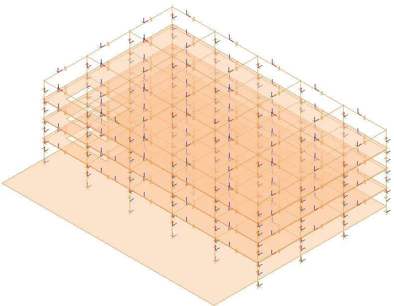
Open the revit software and double click on the structural model we created in week 7
Go to the project browser
Select the analytical model
STEP 2:
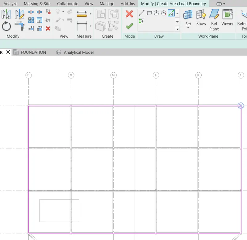
To add the loads , go to the analyze tab

Go to load option
Take the required load conditions
Aplly the load as per requiremet
Select the load
Then change the load parameters in properties panel
Select the load
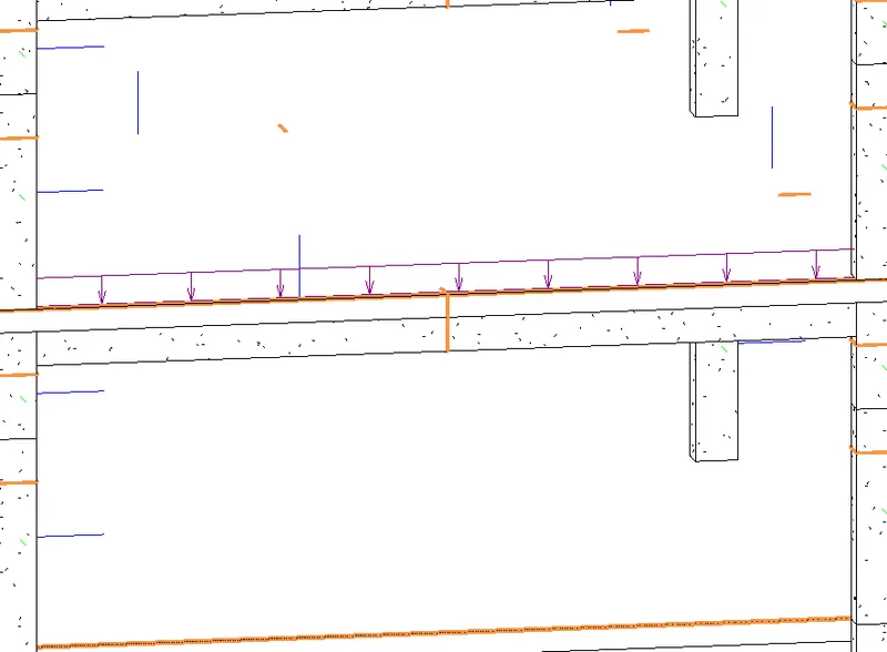
Click on the copy to clipboard
Paste on all assigned levels
Select the required levels
Click ok
STEP 3
To add the load cases go to analyze tab
Go to load cases option
Click add
select required load
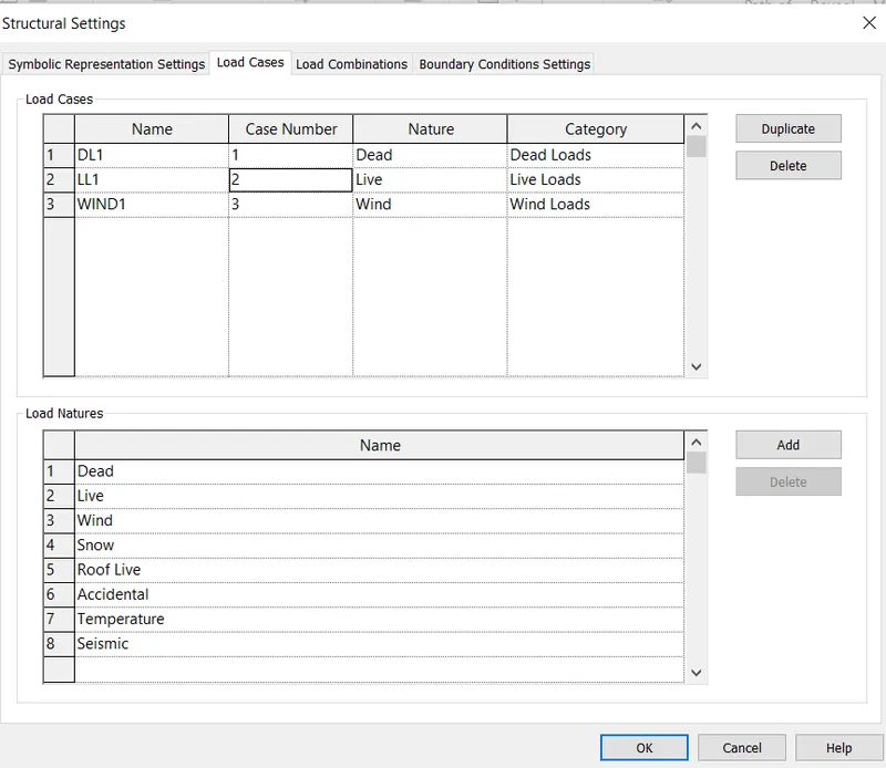
press ok
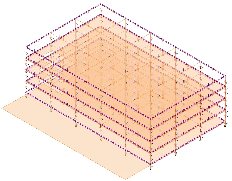
STEP 4
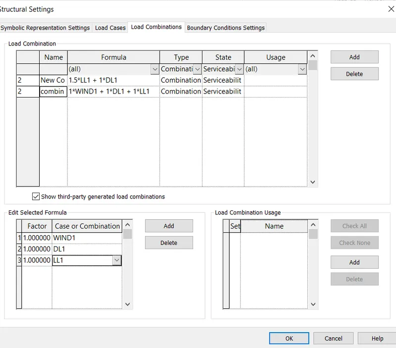
To add the load combinations
Go to the analyze tab
Go to the load combination option
Click add at the load combination
Give the load combinations name
Now click on add at edit selected formula
Click on add required loads
Go to the required factors value
Repeat the same procedure
Create the required load combinations
STEP 5:
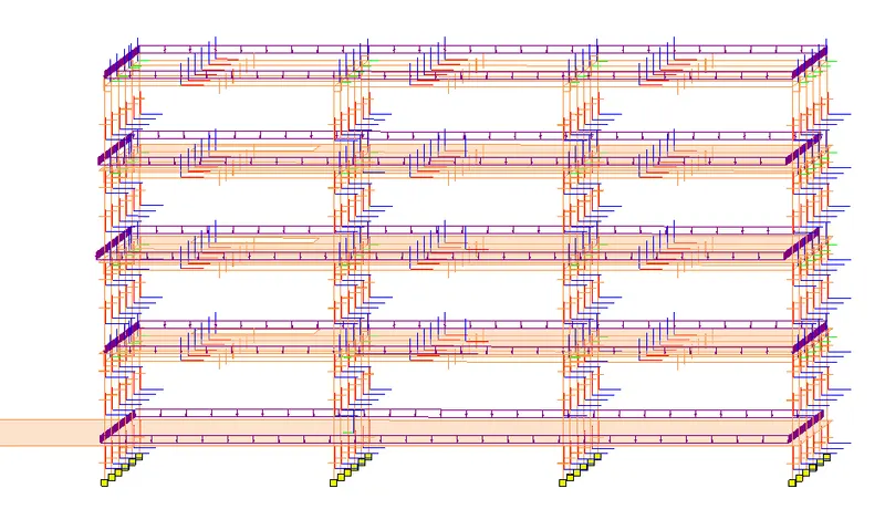
To add the boundary combinations :
Go to analyze tab
Go to boundary combiations option
Select the support type as fixed
Select the foundation analytical point to create the fixed support
STEP 6:
To export the robot structural analysis
Go to analyze tab
Click on dropdown arrow on the robot structural analysis tool kit
Click on robot structural link
Finally click ok
Then open the model in robot structural analysis software
STEP 7:
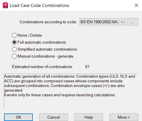
To add the load combinations in robot structural analysis
Go to load tab
Select the automatic combinations
Then select full automatic combinations
CLICK OK
Finally set the load combinations
STEP 8:
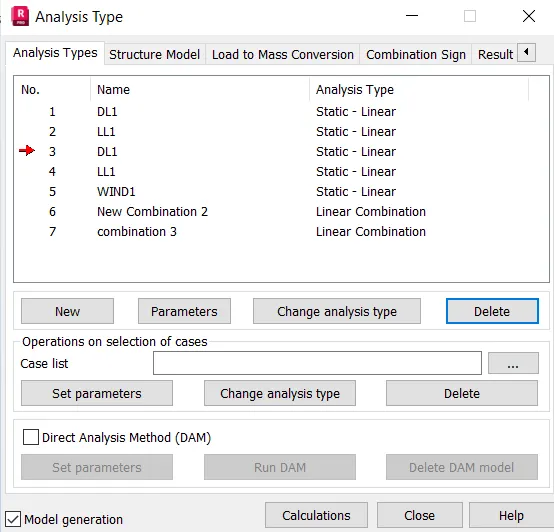
Do the analysis in robot structural analysis software
Go to analysis tab
Select the analysis type
Then click o calculate to compute the structural calculations
STEP 9:
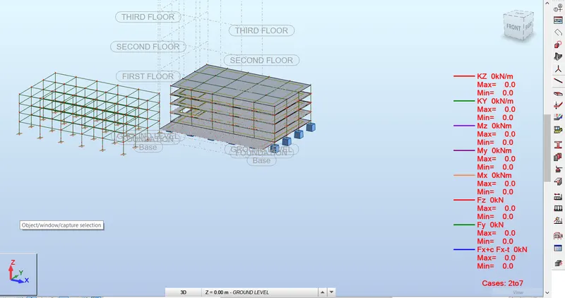
To check the results
Go to the result tab
Click on diagram and bars
To check all the stresses
Go to reactions
Then turn on required parameters
Chcek tick the description box
Moment reactions result for dead and live load
Support reactions result for dead and live load
RESULT:
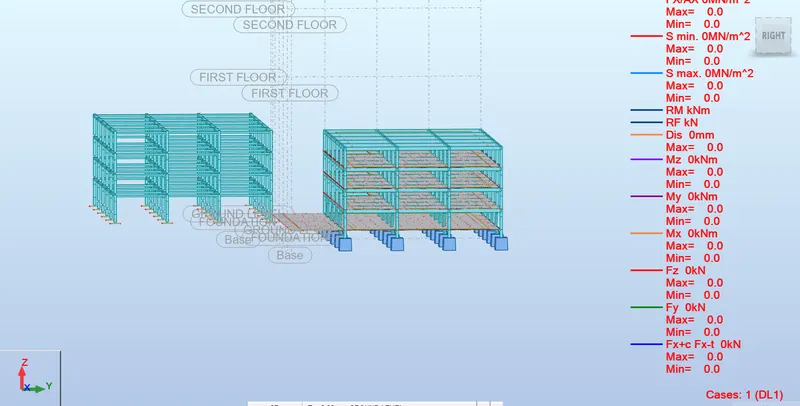
Results for different load cases are produced
Yes, after modelling we have a better approach to the building modelling as Structural analysis establishes the relationship between a structural member’s expected external load and the structure’s corresponding developed internal stresses and displacements that occur within the member when in service. This is necessary to ensure that the structural members satisfy the safety and the serviceability requirements of the local building code and specifications of the area where the structure is located.