Structural analysis of a buidling using Robot Structural Analysis
1) What are HVAC systems? Why are they essential in the modeling of buildings
Aim : To explain about HVAC system and its importance in building modelling.
Introduction
- HVAC is heating, ventilation and cooling system.
- It is provided to create comfort in the building with the minimum usage of the electricity.
- it is provided in building modelling with help of the system tab in the Revit software.
Procedure
- HVAC are systems to regulate the flow of air, heat, and ventilation in a building.
- Overall, the main objective of having an HVAC in a building is to make occupants in a building feel comfortable for them to become healthier, happier, and more productive.
Buildings need HVAC installed in them because:
- HVAC systems are used for controlling the overall climate in a building.
- This means that when it’s warm outside, it balances the temperature to make the inside cooler or warmer during the cold season.
- The air conditioner works during the warmer days while boilers or heaters are turned on during the colder days.
- HVAC fosters enhanced productivity in offices as they feel comfortable. And when they are comfortable, their minds and body tend to function better, leading them to deliver better job results.
- HVAC improves air quality in the building, helping make it appropriate for human breathing and comfort.
- It reduces humidity so occupants can enjoy a better atmosphere.
- This is most especially useful in buildings or underground spaces where ventilation is limited.
- HVAC systems help you achieve more savings when it comes to energy bills.
- Gone are the days where we used fans and old-school air conditioners to feel cooler inside a building or fireplaces to keep us warmer.
- We also don’t have to waste energy when we forget to turn them off at night because modern HVACs are now automatic.
- Schedules and conditions can now be set. For instance, the newer air-conditioner will stop working when it senses the temperature desired is already achieved and will start working again when it senses a drop in temperature.
- Some units can even tell when the occupants already left the premises and automatically shuts down.
- Since the air conditioner won’t work continuously, more energy can be saved.
- Looking at these reasons, besides comfort, energy-saving is another benefit to enjoy from using the proper HVAC system.
Result :
Therefore, importance of the HVAC system is explained above in terms of energy saving and adding the comfort to the occupant in the building.
2) From week 7 assignment, based on the building designed use the same Revit file to design a HVAC system for each floor to cover the topics included in the class.
a. Typical HVAC unit includes Distribution center
b. Collector
c. Ducts
d. Blower
Based on the layout choose appropriate ducts and elevation using property browser and assign the components to appropriate groups to complete modeling of the HVAC unit
Aim : To design a HVAC system in the week 7 assignment Revit file by including different HVAC components such as collector, ducts, blower etc., using the Revit software.
Introduction
- HVAC system is heating, ventilation and cooling system which is added in the system to provide comfort in the building with the use of minimum electricity.
- HVAC system is created in building modelling using the system tab.
- It is important part of building modelling and it is performed by MEP engineer.
Procedure
Step 1
- Open the Revit software, click on new option from home page of the Revit software.
Step 2
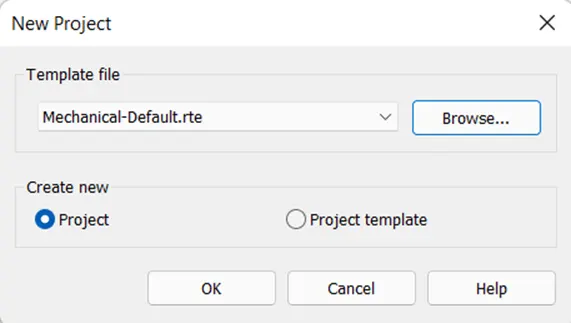
- Select the mechanical default template from new project dialog box and select ok.
Step 3
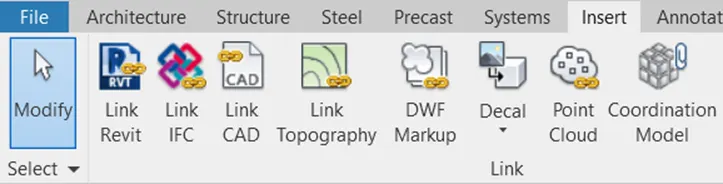
- Go to insert tab, select link Revit option and select the file and open the file to link into the current project.
Step 4
- Go to mech 1 floor plan using project browser.
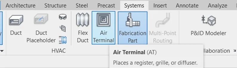
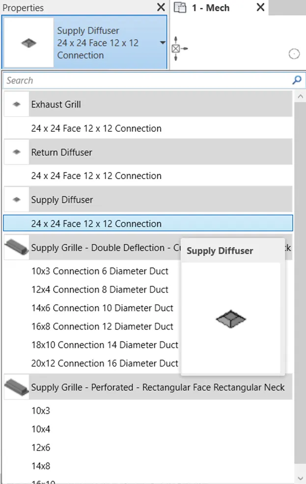
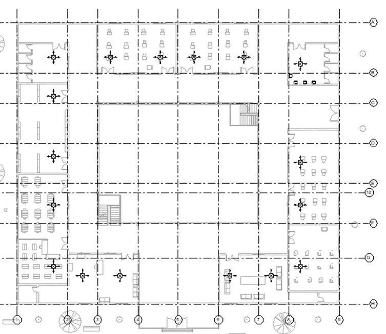
- Go to system tab, select the air terminal tool, select the supply diffuser from properties window and place it in the required position as shown below.
Step 5
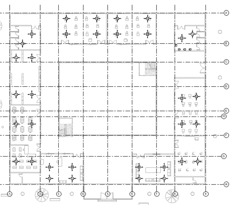
- Similarly again, go to air terminal tool from system tab, select the return diffuser and add it to the required position.
Step 6
- Select all the air terminal units using the filter tool and change the offset of the terminals to 11’9” from properties window.
Step 7
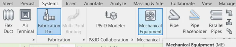
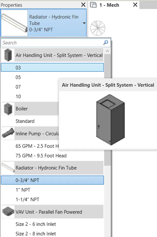
- Go to mechanical equipment from system tab and select the air handling unit from properties window and add it to the required position.
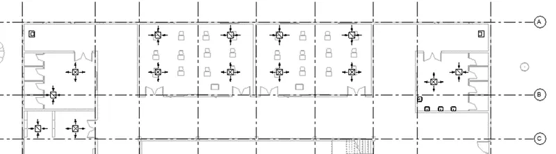
Step 8
- Now, select all the air return diffuser and one of the mechanical equipment using the cursor.
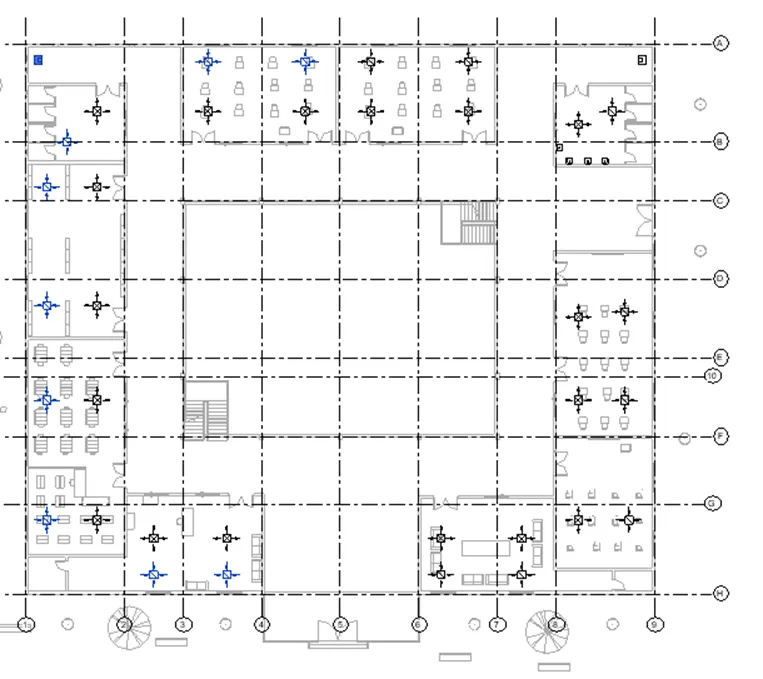
Step 9
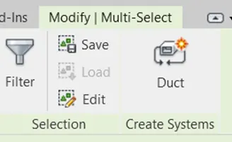
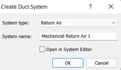
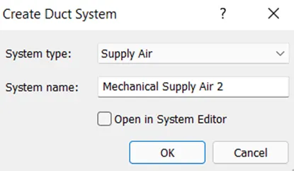
- Select the duct tool from multi select tab, create the duct system by selecting ok in create duct dialog box as air return system 1.
Step 10
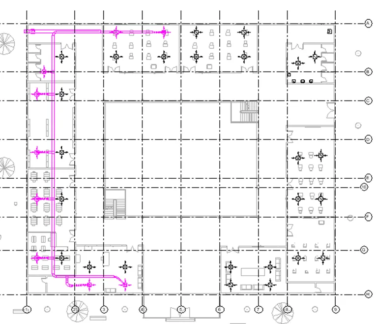
- Select the generate layout tool from duct system tab, select solution type as network, click on setting and set the type of main and branch duct type and its offset distance using
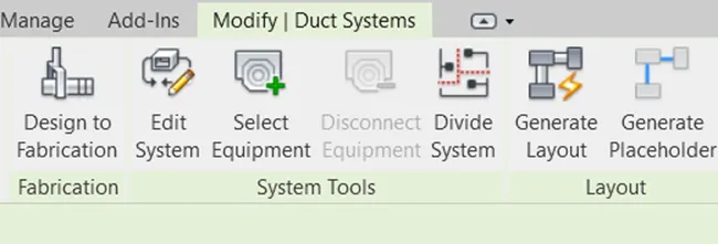

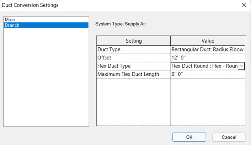
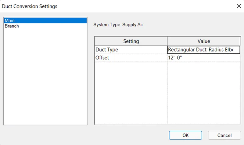
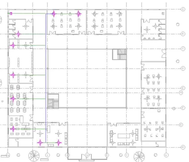
- System is generated as shown below.
Step 11
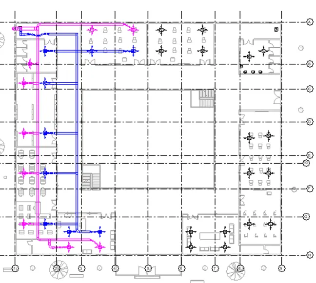
- Similarly select all the air supply units and mechanical equipment and create the air supply system using the similar procedure as shown below.
Step 12
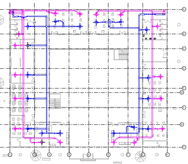
- Similarly create the air terminal system on other side of the building as shown below.
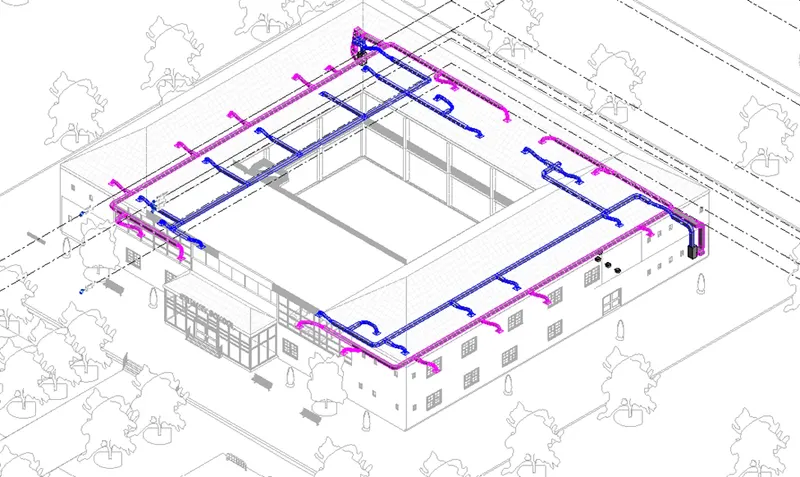
Step 13
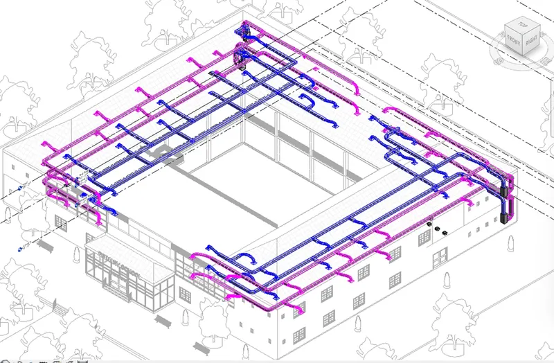
- Now , select all the air terminal and duct system of level 1 by dragging with help of the mouse and select copy from clipboard panel, select paste and select level 2 to copy the similar system in the level 2 as shown below.
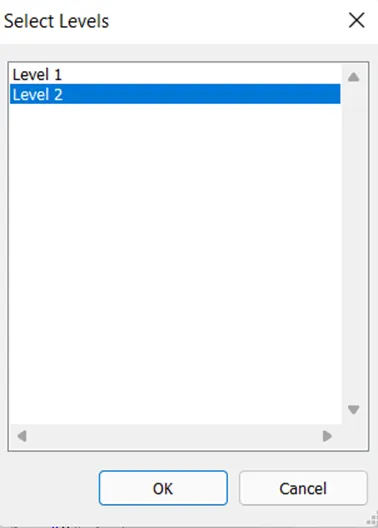
Result :
Therefore, HVAC system is designed in the Revit software by installing air terminals and mechanical equipment as shown below.
3D shaded view is shown below.
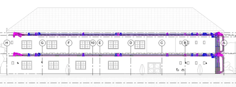
East view
3) Use the add-ins tab to load plug-ins for robot structural analysis to your Revit software
Aim : To load plug-ins for Robot structural analysis in the Revit software using add-ins tab.
Introduction
- While designing structural component of the building analysis of the building is very important which is the process of determining the maximum loads, moments and shear forces etc., coming on the structure.
- It helps to design the structure in terms of safety so that structure serves its functionality without compromising safety and serviceability of the building unit.
- Structural analysis of building is performed using robot structural analysis professional.
Procedure
Step 1
- Open the Revit software, go to shopping cart from the top toolbar of the Revit screen it will open the Autodesk website.

Step 2
- Search for Robot structural analysis professional 2022 from Autodesk website, select the appropriate version of the software, download it and install the software.
- Robot structural analysis gets inserted into Revit software under the analysis tab as shown below..
Result
Therefore, robot structural analysis is added in the Revit software successfully as shown below.

4) Why do we need to assess buildings/analyze while modeling elements? Does design affect modeling in anyways?
Aim : To discuss about the need of analysis of building while modelling the element.
Introduction
- Structural design is the orderly investigation of the stability, strength, and rigidity of structures.
- Structural analysis and design’s main objective is to produce a structure capable of resisting all applied loads without failure during its intended life.
- Structural analysis is the process of calculating and determining the effects of loads and internal forces on a structure, building or object.
Procedure
- Structural Analysis is particularly important for structural engineers to ensure they completely understand the load paths and the impacts the loads have on their engineering design.
- It allows engineers or designers to ensure a piece of equipment or structure is safe for use under the estimated loads it is expected to withstand.
- Structural Analysis can either be performed during design, testing or post-construction and will generally account for the materials used, geometry of the structure and applied loads.
- Structural Analysis usually looks at individual structural elements, and the forces they undergo.
- A structural engineer will look at the structural analysis results for beams, slabs, cables and walls.
- All of these elements have forces applied to them, such as wind loads, dead loads (like self weight) and live loads (like people or vehicles).
- If the structure is erroneously designed or if the actual applied loads exceed the design specifications, the device will probably fail to perform its intended function with serious consequences.
- The primary purpose of a structure is to transmit or support loads. A well-engineered structure greatly minimizes costly failures.
- So it is important for the engineer to review how each of these elements behave under these loads. This is the core focus of structural analysis.
Result
Therefore need of analysis while modelling the elements along with design effect on modelling is discussed above.
5) From the structural model developed in week 6 and 7, export the complete analytical model to robot structural analysis.
a. List your assumptions on what boundary conditions will be realistic for the analysis approach
b. Use the design standards to decide what loads must be applied to floorings based on the type of structure decided
c. List the load combinations and include them in the analysis model
d. Analyze the building and report the following results
i. Maximum Moment in each floor for all Load Combinations
ii. Maximum Displacement in each floor for all Load combinations
iii. Lateral Displacement in building for all Lateral Load combinations
e. After analysis, do you think you have a better approach or idea in modeling structural members?
Aim : To analyze the structural model in the Robot structural analysis by exporting it by using assumed boundary condition, and different load combinations.
Introduction
- Structural analysis of the building can be performed manually for smaller frames but for larger and complex structural frames computer aided software are used.
- Using the Robot structural analysis we can perform the structural analysis of the building by importing the Revit file in robot structural analysis.
Procedure
Assumptions for boundary conditions
- Boundary condition is place on structure where external force or displacement are known.
- At the boundary condition structure interact with environment either through application of external force or through some restrains that imposing displacement.
- That restrains are called as supports.
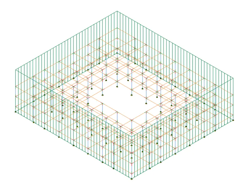
- Here it is assumed that the support are fixed allowing no movements or rotation in any direction.
Loads that must be applied to floorings based on the type of the structure is as follows
- Dead load
- Live load
- Wind load
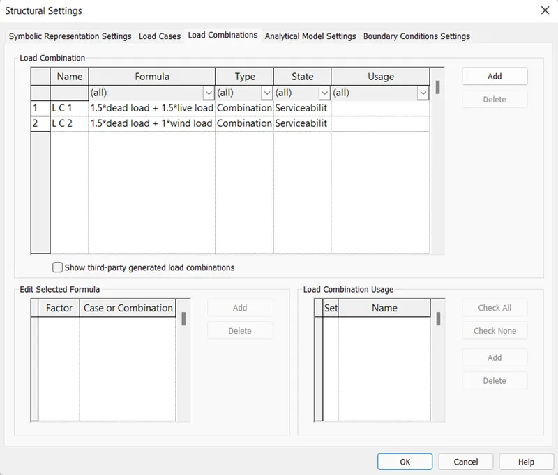
Load combination applied in the school building as per the limit state of collapse is as follows
- 1.5 DL + 1.5 LL
- 1.5 DL + 1 WL
Steps for analysis of building using robot structural analysis.
Step 1
- Open the Revit software and open the structural model created in challenge from 6 to 7.
Step 2
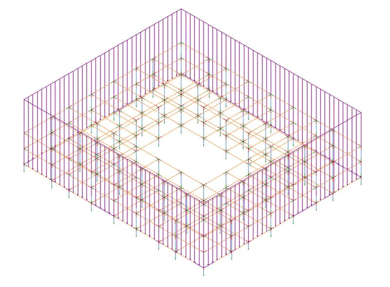
- Open the analytical model using the properties window, then go to analyze tab, click on the loads tool, choose area load, select rectangle from draw panel and place the loads on the model as shown below.
Step 3
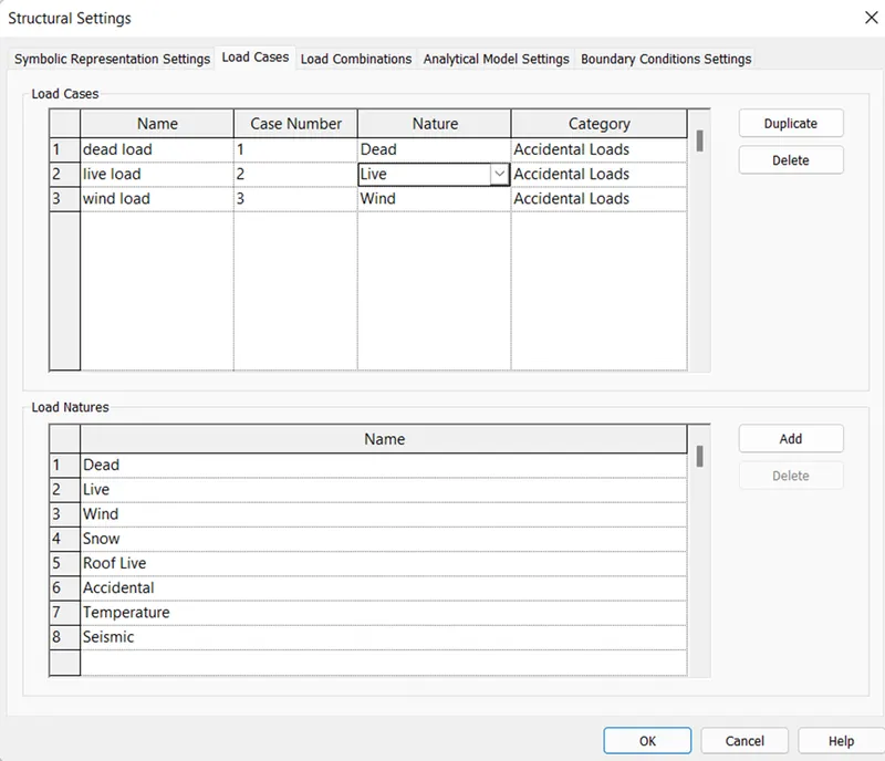
- Select the load cases option from analytical model of analyze tab and add the dead load and live load in load case from structural setting dialog box and select ok as shown below.
Step 4
- Select the load combination tool form analytical model panel and add the load combination as shown below.
Step 5
- Then go to load boundary tool from analytical model panel of analyze tab, select the point as boundary condition and apply the boundary condition to each support as shown below.
Step 6
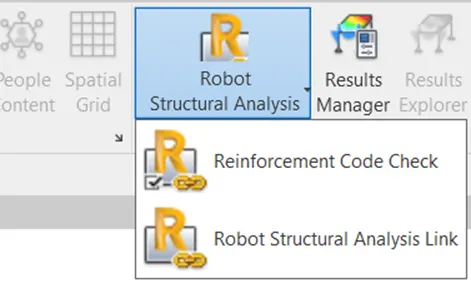
- Now go to Robot structural analysis tool from structural analysis panel and select robot structural analysis link.
Step 7
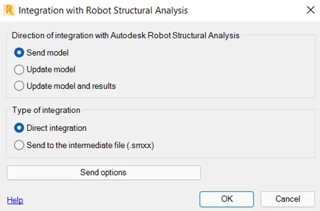
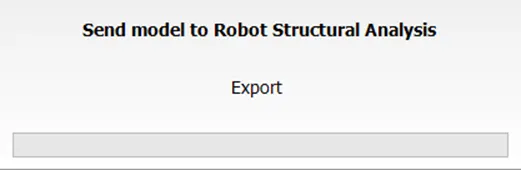
- Select send model and direct integration option and select ok.
Step 8
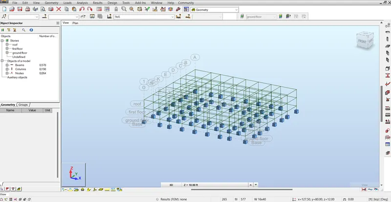
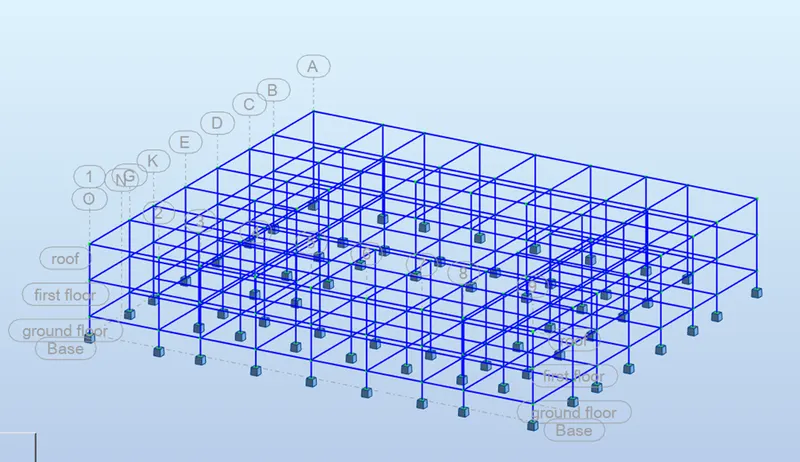
- The model in the robot structural analysis window is shown below.
Step 9
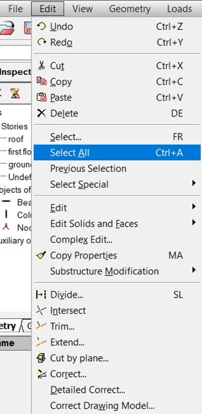
- The from robot structural analysis window, select the edit tab and select select all to select all the members.
Step 10
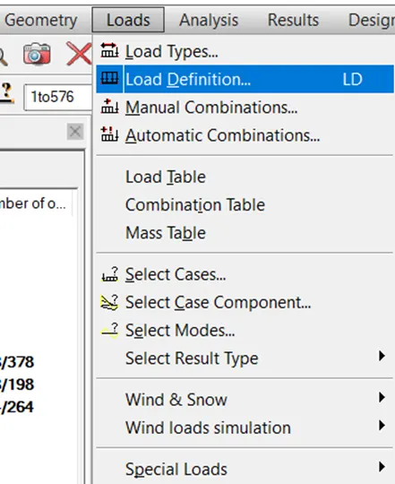
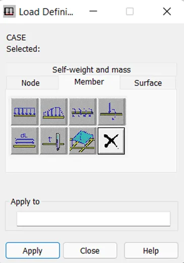
- Now go to load tab, select load definition and select linear load from member tab and select apply and close.
Step 11
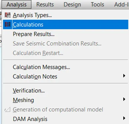
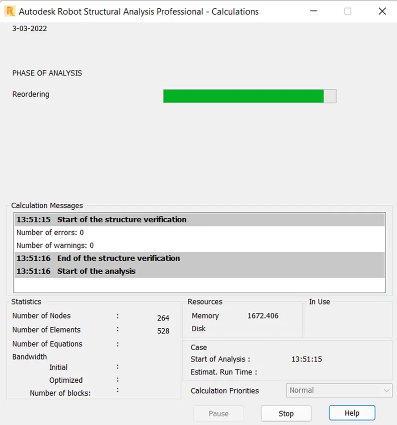
- Go to analysis tab, select the calculations then it will start calculation
Step 12
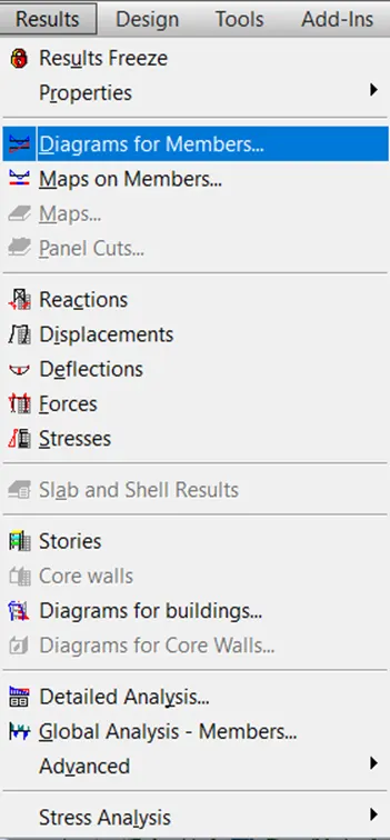
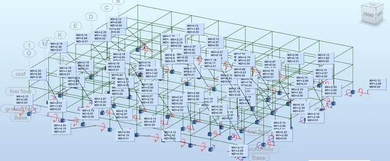
- Now go to diagrams for member tool from result tab and select diagrams for members.
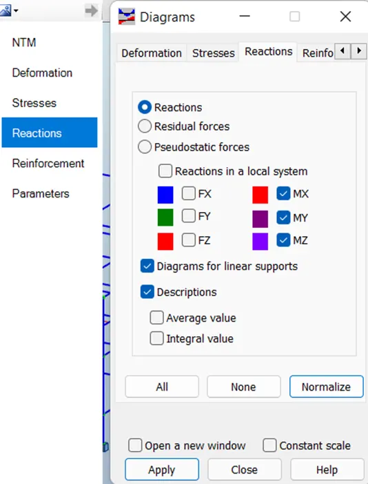
- Select the reactions option and check on the reactions which we want to display on the diagram as shown below.
Step 13
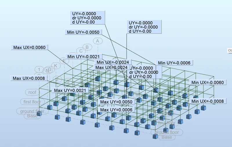
- Similarly analyze the structure for the displacement.
Result :
Analysis of building for maximum moment is shown below.
Analysis of building for maximum displacement in all direction is shown below.
From the above analysis now I got better idea in modelling the structural analysis.
6) What is energy analysis and why do we need to consider it while modeling in Revit?
How does the factor of sustainability improve the quality of your design?
Aim : To explain about the energy analysis and its need to consider while modelling in Revit along with importance of sustainability to improve the quality of the design.
Introduction
- Energy analysis of building is important to estimate energy utilization of the building which helps for modelling the building more efficiently in terms of cost and design of other energy related systems.
- Sustainable building design is important in terms of reducing the negative impact on the environment, and approach towards preservation of surrounding environment.
Procedure
Importance of energy analysis of building
- Performing energy analysis on the building design through all stages, from the earliest conceptual phase through detailed design, to ensure that you are constantly working towards the most energy efficient building possible.
- Energy simulation can help to analyze the movement of energy in, out, and through the rooms and volumes in a building model.
- It helps to estimate the loss and gain of heat through the building so that we can provide effective measures to prevent unnecessary loss of the energy.
- This information can help designers make better informed, cost-effective decisions that improve the performance and reduce the environmental impact of buildings.
- Whole building energy simulation measures expected energy use (fuel and electricity) based on the building's geometry, climate, building type, envelope properties, and active systems (HVAC & Lighting).
- It takes into account the interdependencies of the building as a whole system.
- Use Energy Analysis for Revit to perform energy simulation for conceptual forms and detailed architectural models created in Revit.
- Using the simulation results we can understand the building energy use. Then iterate the designs to improve their sustainability ratings.
- The energy model created from the Revitbuilding model can be displayed in Revit, so you can view and validate the energy model used for analysis.
Importance of sustainable building design to improve quality of design
- Sustainable building design can be defined as one that is constantly evolving and has minimal impact on the environment.
- A sustainable building is one where the structure and processes are environmentally responsible and resource-efficient throughout the lifecycle of the building.
- That includes everything from design and construction, maintenance and renovation, right through to demolition.
- A sustainable building is also designed to preserve the surrounding environment as much as possible, and subsequently using green energy methods, such as renewable energy to operate as a net producer, rather than a net consumer of resources.
- As sustainable architecture and green buildings have grown in popularity and naturally evolved over time.
Six fundamental principles, which govern how sustainable buildings are designed and built. They are:
- Optimize site potential
- Optimize energy use
- Protect and conserve water
- Optimize building space and material use
- Enhance indoor environment quality
- Optimize operational and maintenance practices
Result :
Therefore, importance of energy analysis while modelling the building in Revit and factors of sustainability which improves quality of design are discussed above.