Creating a Floor plan, Footing detail and Isometric view using AutoCad
Draw the cross section of load bearing wall over spread footing, cross section of isolated footing, the line diagram of two-bedroom building, Cross section of a load bearing wall showing foundation details, isometric view of steps and isometric view of gable wall.
Aim:
- To draw the cross section of load bearing wall over spread footing.
- To draw the cross section of isolated footing.
- To draw the line diagram of two-bedroom building.
- To draw cross section of a load bearing wall showing foundation details.
- To draw isometric view of steps.
- To draw isometric view of gable wall.
Introduction
- All above mentioned geometries are drawn using AutoCAD software.
- In AutoCAD software snap mode is invoked using drafting setting
- It will consist of rectangular snap and isometric snap.
- Rectangular snap is 2 D view of drawing in which only two dimensions of drawing are shown.
- Isometric snap is 3D view in which lines are inclined at 30 degrees to x- axis.
Various commands and tools used are
- Rectangle command
- Line command.
- Offset command.
- Copy tool.
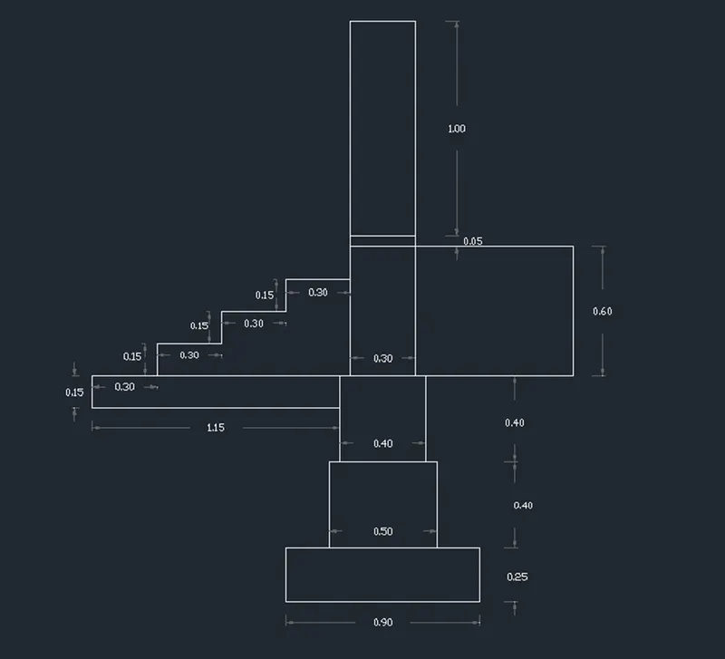
cross section of load bearing wall over spread footing
Procedure
- Open AutoCAD software, type QNEW in command box, press enter
- select default setting as imperial setting, in wizard setting in advanced setup select unit as decimal with 0.000 precision.
- Choose rectangle tool and specify first corner point as 1,1 and press enter
- Click on dimension option in command box
- Specify length of rectangle as 0.9 and press enter.
- Specify width of rectangle as 0.25 and press enter.
- Specify other corner point as 1.9,1.25 and press enter or move the cursor in first quadrant and left click the mouse.
- Type rectangle in command box and press enter.
- Specify fist corner point as 1.2,1.25 and press enter
- Click on area option in command box and type area of rectangle as 0.2 units and press enter.
- Choose length option in command box and type length as 0.5 and press enter.
- Again, type REC in command box and press enter.
- Specify fist corner point as 1.25,1.65 and press enter
- Click on area option in command box and type area of rectangle as 0.16 units and press enter.
- Choose length option in command box and type length as 0.4 and press enter.
- Again, type REC in command box and press enter.
- Specify fist corner point as 1.3,2.05 and press enter
- Click on area option in command box and type area of rectangle as 0.495 units and press enter.
- Choose length option in command box and type length as 0.3 and press enter.
- Choose the line tool, specify first point as 1.3,2.65 and press enter.
- Specify next point as @0.3<0 and press enter.
- Choose offset tool and specify offset distance of 0.05 and press enter
- Select the above drawn line and take offset above the line and press enter.
- Choose rectangle tool and specify first conner point as 1.25,2.05, press enter.
- choose dimension option in command box.
- Specify length as 1.15, press enter and width as 0.15, press enter, move the cursor in third quadrant and press enter.
- For drawing steps, choose line tool, specify first point as 1.3,2.5 and press enter.
- Type next point as @0.3<180, press enter.
- Type next point @0.15<270 and press enter.
- Type next point as @0.3<180, press enter.
- Type next point @0.15<270 and press enter.
- Type next point as @0.3<180, press enter.
- Type next point @0.15<270 and press enter.
- After completion of drawing give dimensions using dimension tool.
Output
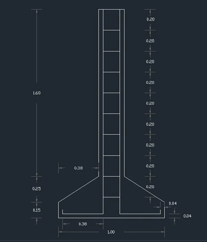
Cross section of isolated footing
Procedure
- Open AutoCAD software, type QNEW in command box, press enter
- Select default setting as imperial setting, in wizard setting in advanced setup select unit as decimal with 0.000 precision.
- Choose line tool, specify first point as 1,1
- Specify next point @0,0.15 and press enter.
- Specify next point @0.38,0.25 and press enter.
- Specify next point @0,1.6 and press enter.
- Specify next point @0.24,0 and press enter.
- Specify next point @0,-1.6 and press enter.
- Specify next point @0.38,-0.25 and press enter.
- Specify next point @0,-0.15 and press enter.
- Click on the close option in command box.
- Choose line tool specify first point 1.42,3 and press enter.
- Specify next point @0,-1.96 and press enter.
- Specify next point @-0.38,0 and press enter.
- Specify next point @0,0.04 and press enter.
- Choose line tool, specify first point 1.58,3 and press enter.
- Specify next point @0,-1.96 and press enter.
- Specify next point @0.38,0 and press enter.
- Specify next point @0,0.04 and press enter.
- Choose line tool, specify first point 1.42,1.2 and press enter.
- Specify next point @0.16,0 and press enter.
- Choose offset tool and type offset distance 0.2 in command box and press enter.
- Select the above drawn line and take eight offsets in upward side of the line.
- After completion of drawing give dimensions using dimension tool.
Output
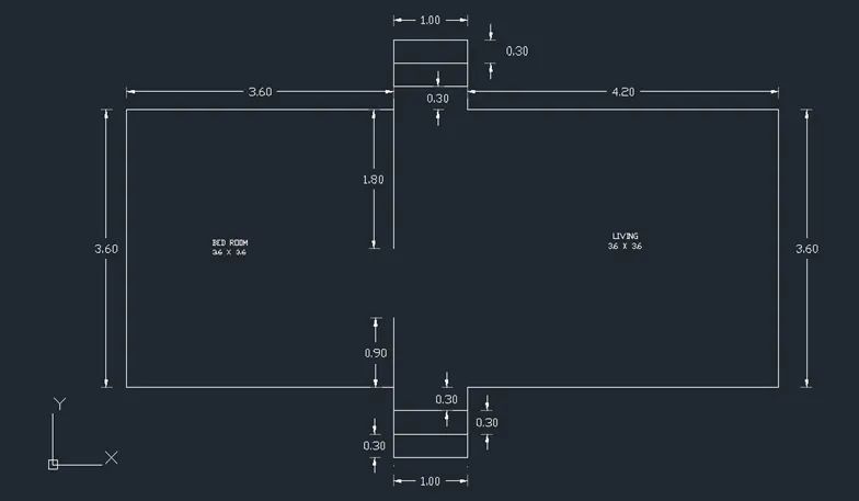
Line diagram of two-bedroom building
Procedure
- Open AutoCAD software, type QNEW in command box, press enter
- select default setting as imperial setting, in wizard setting in advanced setup select unit as decimal with 0.000 precision.
- Type L in command box and press enter.
- Specify start point 1,1 and press enter.
- Specify next point @3.6,0 and press enter.
- Specify next point @0,-0.9 and press enter.
- Specify next point @1,0 and press enter.
- Specify next point @0,0.9 and press enter.
- Specify next point @4.2,0 and press enter.
- Specify next point @0,3.6 and press enter.
- Specify next point @-4.2,0 and press enter.
- Specify next point @0,0.9 and press enter.
- Specify next point @-1,0 and press enter.
- Specify next point @0,-0.9 and press enter.
- Specify next point @-3.6,0 and press enter.
- Click on close option in the command box.
- Choose line tool, specify first point 4.6,1 and press enter.
- Specify next point @0,0.9 and press enter.
- Again, choose line tool and specify first point 4.6,4.6 and press enter.
- Specify next point @0,-1.8 and press enter.
- Choose the offset tool and specify offset distance 0.3 and press enter.
- Select the one-unit length line and take two offsets in downward direction for upward step.
- Similarly, take two offsets in upward direction for the downward steps.
- After completion of drawing give dimensions using dimension tool.
Output
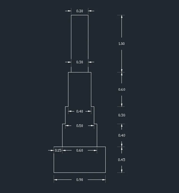
Cross section of a load bearing wall showing foundation details
Procedure
- Open AutoCAD software, type QNEW in command box, press enter
- select default setting as imperial setting, in wizard setting in advanced setup select unit as decimal with 0.000 precision.
- Type REC in command box and press enter.
- Specify first corner point 1,1 and press enter.
- Click on area option in command box and type area of rectangle as 0.405 units and press enter.
- Choose length option in command box and type length as 0.90 and press enter.
- Choose line tool and specify first point as 1.15,1.45 and press enter.
- Specify next point @0.4<90 and press enter.
- Specify next point @0.05<0 and press enter.
- Specify next point @0.3<90 and press enter.
- Specify next point @0.05<0 and press enter.
- Specify next point @0.6<90 and press enter.
- Specify next point @0.4<0 and press enter.
- Specify next point @0.6<270 and press enter.
- Specify next point @0.05<0 and press enter.
- Specify next point @0.3<270 and press enter.
- Specify next point @0.05<0 and press enter.
- Specify next point @0.4<270 and press enter and the escape.
- Type REC in command box and press enter.
- Specify first corner point as 1.3,2.75 and press enter.
- Click on area option in command box and type area of rectangle as 0.30 units and press enter.
- Choose length option in command box and type length as 0.3 and press enter.
- After completion of drawing give dimensions to geometry using dimension tool.
Output
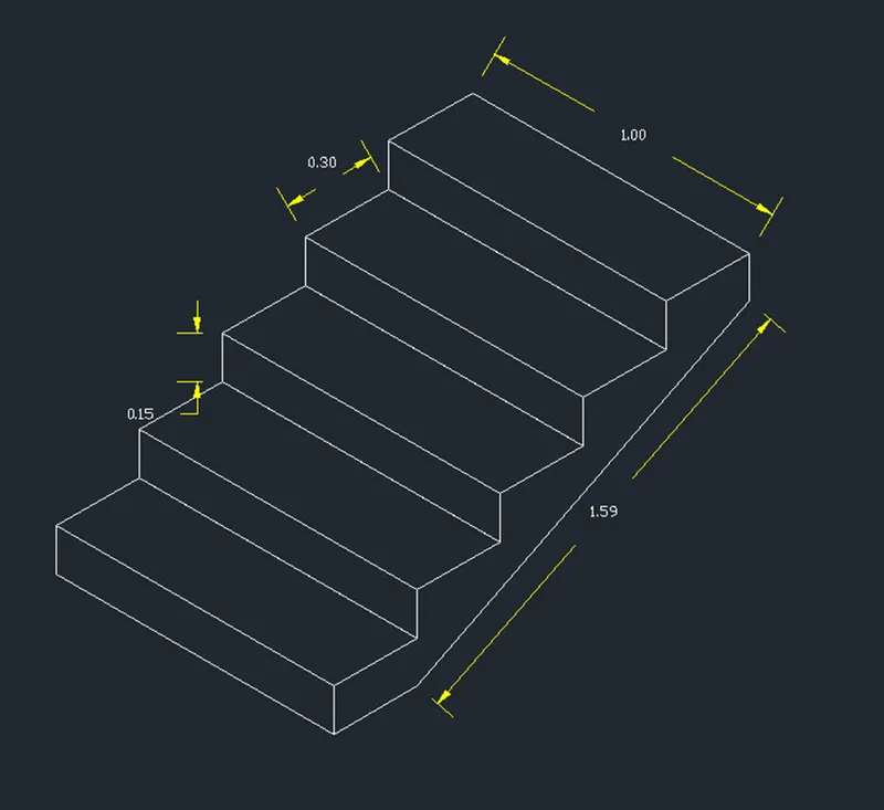
Isometric view of steps
Procedure
- Open AutoCAD software, type QNEW in command box, press enter
- select default setting as imperial setting, in wizard setting in advanced setup select unit as decimal with 0.000 precision.
- Type DS in command box and press enter.
- In snap and grid tab select snap type as isometric snap and click on ok, cursor changes to isoplane left.
- Or click on isometric drafting on status bar and make It on.
- Click on the ortho mode on status bar to restrict directions to 90 and 30 inclined to x axis.
- Choose line tool and specify the first point.
- Move cursor up and type distance 0.15 and press enter.
- Position the cursor in left up, type distance 1 in command box and press enter.
- Position cursor in downward direction, type distance 0.15 and press enter and choose close option in command box.
- Using F5 key change the isoplane left to isoplane top or change it by using isometric drafting setting of status bar.
- Again, choose line tool and specify the first point.
- Position the cursor in right up direction, type distance 0.3 and press enter
- Position cursor in left up direction, type distance 1 and press enter
- Position cursor in left down direction, type distance as 0.15 and press enter
- Choose the copy tool and select the all lines using crossing window and choose base point as corner of first step.
- Specify second point as similar corner point of next step. Repeat the same procedure for three more times and create five steps.
- Using F5 key change the isoplane top to isoplane right.
- Choose line tool and from corner point of topmost step draw line in downward direction having length of 0.15 unit.
- With the line tool draw line of length 0.3 units from first corner point of first step in isoplane right and join the above two drawn line using line tool.
- After completion of drawing give dimensions to geometry by using dimension tool.
Output
Isometric view of gable wall
Procedure
- Open AutoCAD software, type QNEW in command box, press enter
- select default setting as imperial setting, in wizard setting in advanced setup select unit as decimal with 0.000 precision.
- Type DS in command box and press enter.
- In snap and grid tab select snap type as isometric snap and click on ok, cursor changes to isoplane left.
- Or click on isometric drafting on status bar and make It on and select isoplane right.
- Click on the ortho mode on status bar to restrict directions to 90 and 30 inclined to x axis.
- Choose line tool and specify the first point.
- Move the cursor in right direction and type distance 1.5 and press enter.
- Position cursor in up direction and type distance as 1 and press enter.
- Close the geometry, it will create the triangle.
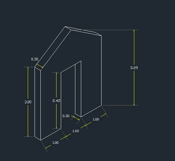
- Again, choose line tool and select closed vertex of triangle as first point and move cursor in downward direction and type distance 3 units and press enter.
- Position the cursor in right up, type distance 1 and press enter.
- Position the cursor in up direction, type distance 2.42 and press enter.
- Position the cursor in right direction, type distance 1 and press enter.
- Now, position the cursor in downward direction, type distance 2.42 and press enter.
- Position the cursor in right direction, type distance 1 and press enter.
- Move the cursor in upward direction, type distance 3 and press enter.
- Now, close the diagram by joining the end point of last line with the topmost vertex of triangle and press enter.
- Now erase the 1.5 and 1 unit lines using erase tool.
- Change isoplane right to isoplane top by pressing F5 key twice.
- Now copy the joined line at distance of 0.3 units from the same line and join the end points of these lines by 0.3 unit lines. Repeat the same procedure for consequent line.
- Change the isoplane to isoplane left by pressing F5 key.
- Choose line tool, select leftmost bottom vertex of diagram, position cursor in left up direction and type distance 0.3 and press enter.
- Position cursor in up direction, type distance 3 and press enter twice.
- Choose copy tool and select above drawn lines in the isoplane left and copy it in isoplane left view of opening.
- Now adjust the just copied 3 unit length line as per opening height by using end vertex of line.
- After completion of drawing give dimensions using dimension tool.
Output
Result
- Hence, the cross section of load bearing wall over spread footing, cross section of isolated footing, the line diagram of two-bedroom building, and cross section of a load bearing wall showing foundation details are drawn successfully in rectangular snap using rectangle command, line tool, offset tool and copy tool.
- Isometric view of steps and isometric view of gable wall is drawn successfully in isometric snap using line tool and copy tool.
- The outputs for all the geometries are obtained by following the above-mentioned procedure are as shown above.