Creation of geometries by Coordinate system methods using AutoCad
Create the geometries from P1 to P2 using all the coordinates system methods. You need to use the line tool to create the geometries. Where required you need to use circle tool. Please read the drawings and find out the missing dimensions before working on the sketches.
Note: Use the imperial template and the decimal units to draft the features. Dimensions are there for references.
civil related problem
draw the profile and the trusses using any coordinate system methods. The dimensions are there for references.
Aim:
- To create geometries P1 and P2 using all the coordinates system methods by using line tool.
- To create geometries from P4 to P10 by using any one coordinate system method using line tool.
- To draw the profile and the trusses using any coordinate system methods using line tool and circle tool wherever required.
Introduction
Coordinate system
There are basically three coordinate systems
- Absolute coordinate system: Plotting points with respect to origin,
- Relative coordinate system: Plotting next point with respect to previous point.
- Relative rectangular coordinate system
- Relative polar coordinate system
- Direct distance entry system: Plotting next point by positioning the cursor in desired direction and mentioning the distance directly.
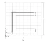
Creating P-1 drawing by using all coordinate systems
Creating P-1 drawing using absolute coordinate system method
Procedure
- Type L in command box or use line tool from tool bar or menu bar or any other convenient method.
- Specify the coordinates of first point 2,1 in the command box and press enter button.
- Then specify or type the next point 2,7 in command box and press enter button.
- Then specify the next point 8,7 in command box and press enter button.
- Then specify the next point 8,6 in command box and press enter button.
- Then specify the next point 3,6 in command box and press enter button.
- Then specify the next point 3,2 in command box and press enter button.
- Then specify the next point 8,2 in command box and press enter button.
- Then specify the next point 8,1 in command box and press enter button.
- The close the drawing using close option in command box or type CLOSE in command box or type the coordinates of first point 2,1 and press enter.
Output
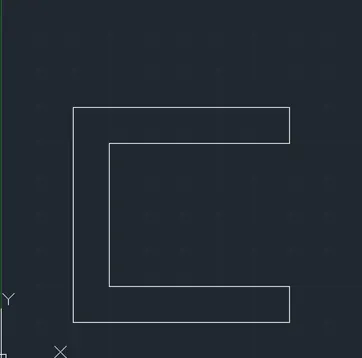
Creating P-1 drawing using relative rectangular coordinate system method.
Procedure
- Type L in command box or use line tool from tool bar or menu bar or any other convenient method.
- Type absolute coordinates 2,1 in command box and press enter.
- Then type or specify next point as @0,6 and press enter
- Then type next point as @6,0 in command box and press enter.
- Then type next point as @0,-1 in command box and press enter.
- Then type next point as @-5,0 in command box and press enter.
- Then type next point as @0,-4 in command box and press enter.
- Then type next point as @5,0 in command box and press enter.
- Then type next point as @0,-1 in command box and press enter.
- Then type next point as @6,0 in command box and press enter button or click on close option in command box.
Output
Creating P-1 drawing using relative polar coordinate system method.
Procedure
- Type L in command box or use line tool from tool bar or menu bar or any other convenient method.
- Type absolute coordinates 2,1 in command box and press enter.
- Then type or specify next point as @6<90 and press enter
- Then type next point as @6<0 in command box and press enter.
- Then type next point as @1<270 in command box and press enter.
- Then type next point as @5<180 in command box and press enter.
- Then type next point as @4<270 in command box and press enter.
- Then type next point as @5<0 in command box and press enter.
- Then type next point as @1<270 in command box and press enter.
- Then type next point as @6<180 in command box and press enter button or click on close option in command box.
Output
Creating P-1 drawing using direct distance entry method.
Procedure
- Type L in command box or use line tool from tool bar or menu bar or any other convenient method.
- Type or specify the first point by absolute coordinate method by typing 2,1 and the press enter button.
- Switch on the ortho mode in status bar.
- Position the cursor upward in positive Y direction and type distance 6 in the command box and press enter.
- Then position the cursor rightward in positive X direction and type distance as 6 in command box and press enter.
- Then position the cursor downward in negative Y direction and type distance as 1 in command box and press enter.
- Then position the cursor leftward in negative X direction and type distance as 5 in command box and press enter.
- Then position the cursor downward in negative Y direction and type distance as 4 in command box and press enter.
- Then position the cursor rightward in positive X direction and type distance as 5 in command box and press enter.
- Then position the cursor downward in negative Y direction and type distance as 1 in command box and press enter.
- Then choose close option in command box or position the cursor in left negative X direction and type distance 6 and press enter.
Output
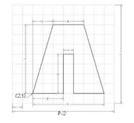
Creating P-2 drawing by using all coordinate systems
Creating P-2 drawing using absolute coordinate system method
Procedure
- Type L in command box or use line tool from tool bar or menu bar or any other convenient method.
- Specify the coordinates of first point 2,1 in the command box and press enter button.
- Then specify or type the next point 4,8 in command box and press enter button.
- Then specify the next point 7,8 in command box and press enter button.
- Then specify the next point 9,1 in command box and press enter button.
- Then specify the next point 6,1 in command box and press enter button.
- Then specify the next point 6,5 in command box and press enter button.
- Then specify the next point 5,5 in command box and press enter button.
- Then specify the next point 5,1 in command box and press enter button.
- The close the drawing using close option in command box or type CLOSE in command box or type the coordinates of first point 2,1 and press enter.
output
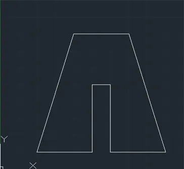
Creating P-2 drawing using relative rectangular coordinate system method
Procedure
- Type L in command box or use line tool from tool bar or menu bar or any other convenient method.
- Type absolute coordinates 2,1 in command box and press enter.
- Then type or specify next point as @2,7 and press enter
- Then type next point as @3,0 in command box and press enter.
- Then type next point as @2,-7 in command box and press enter.
- Then type next point as @-3,0 in command box and press enter.
- Then type next point as @0,4 in command box and press enter.
- Then type next point as @-1,0 in command box and press enter.
- Then type next point as @0,-4 in command box and press enter.
- Then type next point as @-3,0 in command box and press enter button or click on close option in command box.
output
Creating P-2 drawing using relative polar coordinate system method
Procedure
- Type L in command box or use line tool from tool bar or menu bar or any other convenient method.
- Type absolute coordinates 2,1 in command box and press enter.
- Then type or specify next point as @7.280<74.055 and press enter
- Then type next point as @3<0 in command box and press enter.
- Then type next point as @7.280<286 in command box and press enter.
- Then type next point as @3<180 in command box and press enter.
- Then type next point as @4<90 in command box and press enter.
- Then type next point as @1<180n command box and press enter.
- Then type next point as @4<270 in command box and press enter.
- Then type next point as @3<180 in command box and press enter button or click on close option in command box.
output
Creating P-2 drawing using direct distance entry method.
Procedure
- Type L in command box or use line tool from tool bar or menu bar or any other convenient method.
- Type or specify the first point by absolute coordinate method by typing 2,1 and the press enter button.
- Switch on the ortho mode of status bar.
- Then position the cursor rightward in positive X direction at angle 0 and type distance as 3 in command box and press enter.
- Position the cursor upward in positive Y direction and type distance 4 in the command box and press enter.
- Then position the cursor rightward in positive X direction and type distance as 1 in command box and press enter.
- Then position the cursor downward in negative Y direction and type distance as 4 in command box and press enter.
- Then position the cursor rightward in positive X direction and type distance as 3 in command box and press enter.
- Switch off the ortho mode and switch on the dynamic input on the status bar.
- Move the cursor at angle of 105.945 and type distance as 7.280 and press enter.
- Then position the cursor leftward in negative X direction and type distance as 3 and press enter.
- Then choose close option in command and close the drawing.
Output
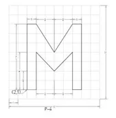
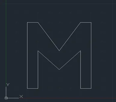
Creating P-4 drawing using absolute coordinate system method
Procedure
- Type L in command box or use line tool from tool bar or menu bar or any other convenient method.
- Specify the coordinates of first point 2,1 in the command box and press enter button.
- Then specify or type the next point 2,8 in command box and press enter button.
- Then specify the next point 3,8 in command box and press enter button.
- Then specify the next point 5,5 in command box and press enter button.
- Then specify the next point 7,8 in command box and press enter button.
- Then specify the next point 8,8 in command box and press enter button.
- Then specify the next point 8,1 in command box and press enter button.
- Then specify the next point 7,1 in command box and press enter button.
- Then specify the next point 7,5 in command box and press enter button.
- Then specify the next point 5,3 in command box and press enter button.
- Then specify the next point 3,5 in command box and press enter button.
- Then specify the next point 3,1 in command box and press enter button.
- The close the drawing using close option in command box or type CLOSE in command box or type the coordinates of first point 2,1 and press enter.
Output
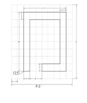
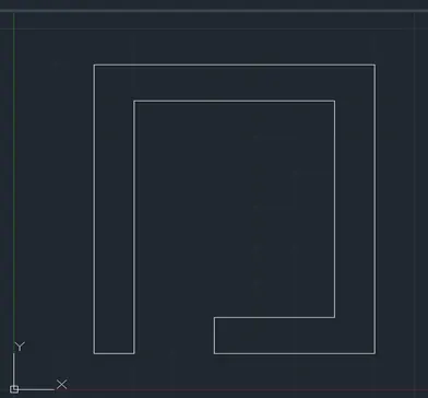
Creating P-5 drawing using direct distance entry method
Procedure
- Switch on the ortho mode of status bar
- Choose line tool or type L in command box and press enter.
- Position the cursor in upward direction and type distance 8 in command box and press enter.
- Then position the cursor in right direction and type distance as 7 in the command box and press enter.
- Then position the cursor in downward direction and type distance 8 in the command box and press enter.
- Position the cursor in left direction and type distance as 4 in command box and press enter.
- Position the cursor in upward direction and type distance 1 in command box and press enter.
- Position the cursor in right direction and type distance 3 in the command box and press enter.
- Then position the cursor in upward direction and type distance 6 in the command box and press enter.
- Then position the cursor in left direction and type distance as 5 in the command box and press enter.
- Then position the cursor in downward direction and type distance 7 in the command box and press enter.
- Then choose the close option in the command box or position the cursor in left direction and type distance 1 in command box and press enter.
output
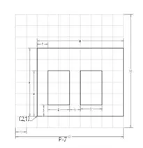
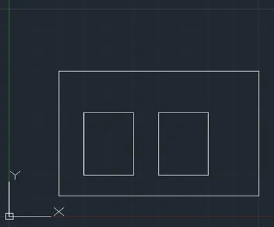
Creating P-7 drawing using absolute coordinate system method
Procedure
- Choose the line tool or type L in command box and press enter.
- Type start point 2,1 in the command box and press enter.
- Type the next point 2,7 in command box and press enter.
- Then type next point 10,7 in command box and press enter.
- Then type next point 10,1 in command box and press enter.
- Then choose the close option in the command box.
- Again, choose the line tool and specify or type the start point 3,2 in the command box and press enter.
- Type the next point 3,5 in command box and press enter.
- Type the next point 5,5 in command box and press enter.
- Then type next point 5,2 in command box and press enter.
- Then choose the close option in the command box.
- Again, choose the line tool and specify or type the start point 6,2 in the command box and press enter.
- Type the next point 6,5 in command box and press enter.
- Type the next point 8,5 in command box and press enter.
- Then type next point 8,2 in command box and press enter.
- Then choose the close option in the command box.
output
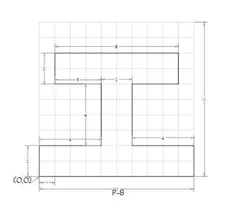
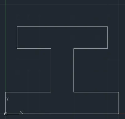
Creating P-8 drawing using relative rectangular coordinate system method
Procedure
- Type L in command box and press enter or choose the line tool.
- Type absolute coordinates of start point as 0,0 in command box and press enter.
- Then type or specify next point as @0,2 and press enter
- Then type next point as @4,0 in command box and press enter.
- Then type next point as @0,4 in command box and press enter.
- Then type next point as @-3,0 in command box and press enter.
- Then type next point as @0,2 in command box and press enter.
- Then type next point as @8,0 in command box and press enter.
- Then type next point as @0,-2 in command box and press enter.
- Then type next point as @-3,0 in command box and press enter.
- Then type next point as @0,-4 in command box and press enter.
- Then type next point as @4,0 in command box and press enter
- Then type next point as @0,-2 in command box and press enter.
- Then type next point as @10,0 in command box and press enter button or click on close option in command box.
output
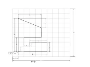
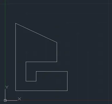
Creating P-9 drawing using absolute coordinate system method
Procedure
- Type L in command box or use line tool from tool bar or menu bar or any other convenient method.
- Specify the coordinates of first point 1,1 in the command box and press enter button.
- Then specify or type the next point 1,8 in command box and press enter button.
- Then specify the next point 5,6 in command box and press enter button.
- Then specify the next point 5,4 in command box and press enter button.
- Then specify the next point 2,4 in command box and press enter button.
- Then specify the next point 2,2 in command box and press enter button.
- Then specify the next point 3,2 in command box and press enter button.
- Then specify the next point 3,3 in command box and press enter button.
- Then specify the next point 6,3 in command box and press enter button.
- Then specify the next point 6,1 in command box and press enter button.
- The close the drawing using close option in command box or type CLOSE in command box or type the coordinates of first point 1,1 in command box and press enter.
output
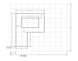
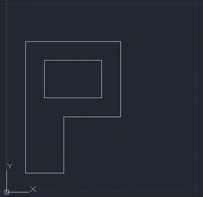
Creating P-10 drawing using relative rectangular coordinate system method
Procedure
- Type L in command box and press enter or choose the line tool.
- Type absolute coordinates of start point as 1,1 in command box and press enter.
- Then type or specify next point as @0,7 and press enter
- Then type next point as @5,0 in command box and press enter.
- Then type next point as @0,-4 in command box and press enter.
- Then type next point as @-3,0 in command box and press enter.
- Then type next point as @0,-3 in command box and press enter.
- Then choose the close option in the command box.
- Again, choose the line tool and specify or type the start point 2,5 in the command box and press enter.
- Then type next point as @0,2 in command box and press enter.
- Then type next point as @3,0 in command box and press enter.
- Then type next point as @0,-2 in command box and press enter.
- Then type next point as @-3,0 in command box and press enter button or click on close option in command box.
output
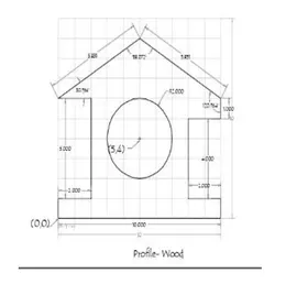
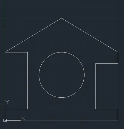
Drawing the profile of wood using relative rectangular coordinate system method
Procedure
- Choose the line tool.
- Type absolute coordinates of start point 0,0 in command box and press enter.
- Then type or specify next point as @0,1 in command box and press enter
- Then type next point as @2,0 in command box and press enter.
- Then type next point as @0,5 in command box and press enter.
- Then type next point as @-2,0 in command box and press enter.
- Then type next point as @5,3 in command box and press enter.
- Then type next point as @5,-3 in command box and press enter.
- Then type next point as @0,-1 in command box and press enter.
- Then type next point as @-2,0 in command box and press enter.
- Then type next point as @0,-4in command box and press enter.
- Then type next point as @2,0 in command box and press enter.
- Then type next point as @0,-1 in command box and press enter.
- Then type next point as @-10,0 in command box and press enter button or click on close option in command box
- Type C or CIRCLE in the command box and press enter.
- Then specify or type the center point coordinate of circle as 5,4 in command box and press enter.
- Then specify radius of circle as 2 in the command box and press enter.
output
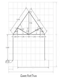
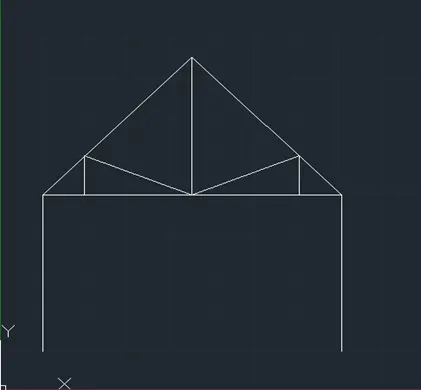
Drawing the Queen Post Truss using relative polar coordinate system method
Procedure
- Choose the line command.
- Specify the start point 1,1 in the command box and press enter.
- Type the next point as @4<90 in command box and press enter.
- Type the next point as @5<45 in command box and press enter.
- Type the next point as @5<315 in command box and press enter.
- Type the next point as @4<270 in command box and press enter.
- Type the next point as @4<90 in command box and press enter twice.
- Again, choose line tool and type @7.072<0 in command box and press enter twice.
- Choose the line tool and specify first point as 1,5 in command box and press enter.
- Specify the next point @1<90 in the command box and press enter.
- Then specify next point @2.726<338.480 in command box and press enter.
- Then specify next point @2.726<21.520 in command box and press enter.
- Specify next point @1<270 in command box and press enter twice.
- Again, choose line tool and specify the point 4.536,5 in command box and press enter.
- Specify next point as @2.536<90 in command box and press double enter.
output
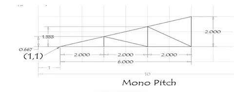
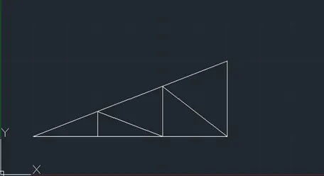
Drawing the Mono Pitch absolute coordinate system method
Procedure
- Type L in command box and press enter.
- Specify the start point 1,1 in command box and press enter.
- Specify next point 7,1 in command box and press enter.
- Then specify or type next point 7,3 in command box and press enter.
- Close the drawing by choosing close in the command box.
- Again, choose the line tool and specify start point as 3,1 in command box and press enter.
- Specify next point 3,1.667 in the command box and press enter.
- Specify next point 5,1 in command box and press enter.
- Then specify next point 5,2.333 in command box and press enter.
- Specify the next point 7,1 in command box and press enter twice.
Output
Result:
- geometries P-1 and P-2 are drawn successfully using all the coordinates system methods.
- geometries from P-4 to P-10 are drawn successfully by using one of the coordinate system method as mentioned above.
- Profile of wood, Queen Post Truss and mono pitch is drawn successfully by using method as mentioned above.
- By following the procedure as mentioned above the outputs are obtained as shown above.