Structural analysis of a buidling using Robot Structural Analysis
1) What are HVAC systems? Why are they essential in the modeling of buildings?
What are HVAC systems?
HVAC (Heat Ventilation and Air Conditioning) systems are mechanical setups arranged for buildings to maintain the suitable temperature within the structures so as to provide environmental ease to the building inhabitants in different seasons. At the same time, HVAC systems help keep in check the quality of air received by the building. The air that is supposed to enter the structure is first filtered by the mechanical HVAC system to ensure the safety and health of the occupants. There are primarily two regulators in a typical HVAC system that are supply and return diffusers. Supply diffusers are meant to bring in the fresh air inside the building while the return diffusers are supposed to act as an exhaust to transfer out unrequired heat and air to the outside of the building. Both these regulators are connected to the air handling unit via a duct which in combination makes a complete HVAC system.
Why is an HVAC system essential in the modeling of buildings?
Any building model is incomplete without a proper ventilation system to regulate fresh air throughout the structure. In addition, an efficient HVAC system also improves the overall functionality of a building model by keeping a suitable temperature inside the structure. Moreover, the HVAC system also filters out the hazardous air molecules making it safer for the building occupants to breathe in. An HVAC system allows for better heat management which is essential for the durability of materials. As we know, several structural components expand or contract due to the significant increase or decrease in the surrounding temperature. So, an effective HVAC system makes sure that the building temperature is always kept in check and thus makes way for decreased maintenance costs. Also, the HVAC system maintains adequate humidity levels inside the building which is essential to protect the electronic appliances present in the structure.
2) From the week 7 assignment, based on the building design use the same Revit file to design an HVAC system for each floor to cover the topics included in the class.
a. Typical HVAC unit includes Distribution center
b. Collector
c. Ducts
d. Blower
STEPWISE PROCEDURE TO INSTALL AN HVAC SYSTEM FOR YOUR REVIT MODEL:
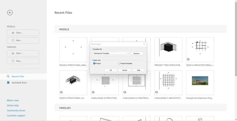
- Open up a new mechanical template
- Go to the new tab and click on the project.
- From the dropdown list of templates, choose a mechanical one.
- Click on OK to confirm and the mechanical file will open which has every system unit required to complete an HVAC system.
- Link your Revit model to the new mechanical template
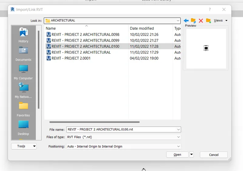
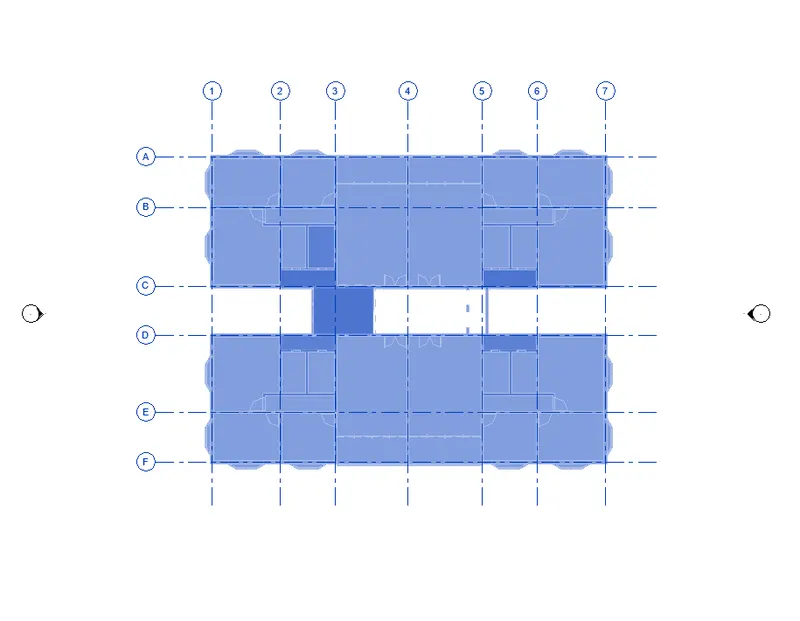
- Go to the insert tab and click on the link Revit option.
- A dialogue box will open where you can specify the file you want to link up.
- Choose the file path for your previous project and hit enter.
- Select the linkage method as per the project specifications like shared coordinates or origin to origin etc.
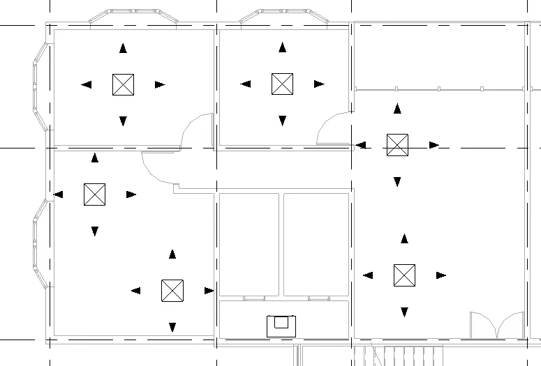
- Add the supply diffusers and the air handling unit at the suitable locations
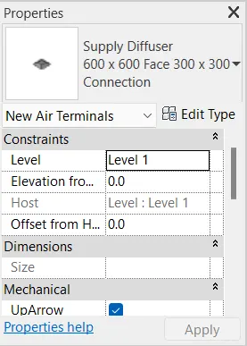
- Go to the systems tab and click on the add component.
- You can also load family to insert the supply diffuser into your project.
- Once you load the family type, you can start adding them into the building wherever required.
- Thus, a suitable number of supply diffusers are added to the flat as per the project requirements.
- Similarly, load an air handling unit and place it at a convenient location where it is easily connectable to every diffuser unit.
- Create the duct route for diffusers and AHU
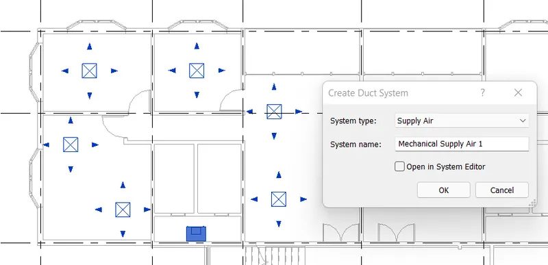
- To create the duct route, select all the elements which you want to join via the duct.
- In our case, select all of the diffusers and the AHU and then click on the create duct option.
- And once creating the duct, you have the option to select anyone from the listed possible routes for the duct.
- Generate layout and system settings
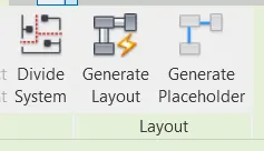
- After confirming the duct route, you can click on the generate layout to form the duct system.
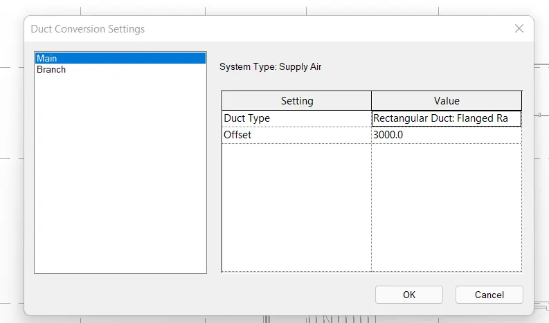
- And once you generate the layout, you can go ahead and change the system settings from the settings panel.
- From the settings dialogue box, you can change the type of duct and also its elevation from the ground level based on the floor height of your project.
- Supply system layout for flat 1
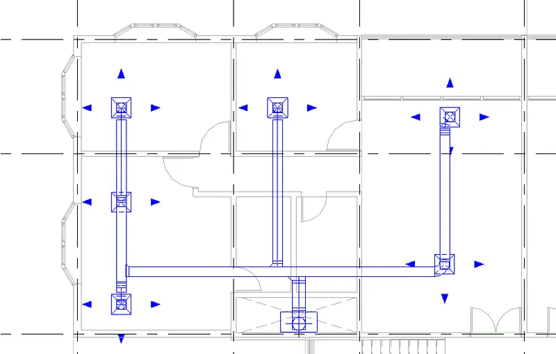
- Now, follow the exact procedure and link up the return diffusers to complete the HVAC system for the entire floor and then copy and align it with all levels to design the system for the entire building.
HVAC SYSTEM FOR FLAT ONE:
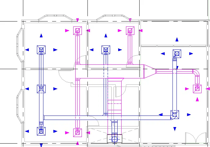
HVAC SYSTEM FOR FLOOR ONE:
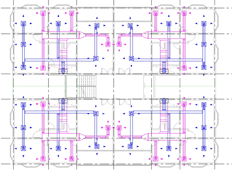
COPY AND ALIGN THE DESIGN FOR ALL FLOORS
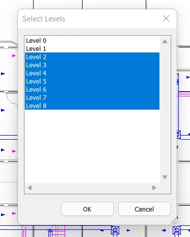
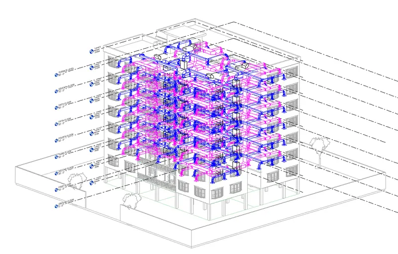
HVAC DESIGN FOR THE ENTIRE PROJECT:
3) Use the add-ins tab to load plug-ins for robot structural analysis to your Revit software.
STEPWISE PROCEDURE TO ADD THE ROBOT STRUCTURAL ANALYSIS TOOLKIT TO YOUR REVIT SOFTWARE:
- Open the AutoDesk app store
- On the top right side of your Revit screen, you can find a shopping cart logo that directs you to the official AutoDesk online app store.
- So, click on that particular shopping cart logo.
- Once you click on that logo, the following webpage will open up on your computer.
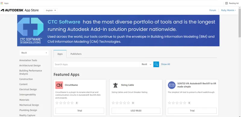
- Search for the structural analysis toolkit
- From the search bar available on the official website, you can search for the AutoDesk products you want for your system.
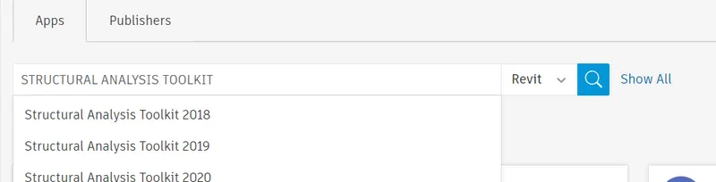
- Thus, type in the Structural Analysis Toolkit and it will direct you towards the Robot Structural Analysis Add-in.
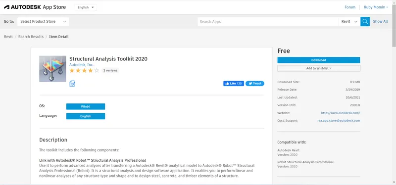
- Look for the latest version from the list based on your Revit model and hit the download button.
- Download the program and install it
- After finding the version based on your Revit model, you can easily download it at an appropriate location on your computer.
- The add-in is totally free so you won't be charged anything for it.
- Also, make sure you have the Robot Structural Analysis Software already installed on your computer before downloading its add-in.
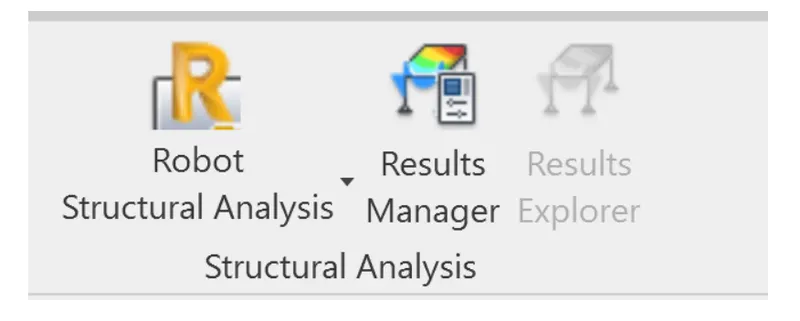
- The add-in will only show up on your Revit screen if you already have installed the full Robot Structural Analysis software on your system.
4) Why do we need to assess buildings/analyze while modeling elements? Does design affect modeling in anyways?
Analyzing the Structural stability of the buildings is very crucial as it determines the size of various structural elements like beams, columns, etc. Without proper calculations and results, no Building Information can be modeled with 100% precision. Often, the Architectural design of the building needs to be adjusted based on the calculations carried out while executing the building analysis. Hence, the collaboration between the Architect and the Structural engineer is essential for efficient planning and design of buildings.
5) From the structural model developed in weeks 6 and 7, export the complete analytical model to robot structural analysis.
a. List your assumptions on what boundary conditions will be realistic for the analysis approach
b. Use the design standards to decide what loads must be applied to floorings based on the type of structure decided
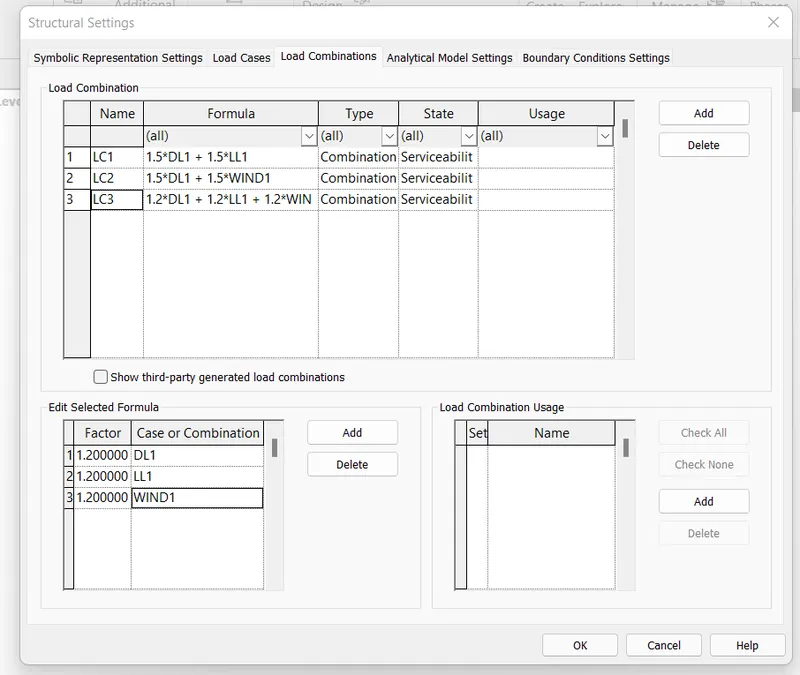
c. List the load combinations and include them in the analysis model
d. Analyze the building and report the following results
i. Maximum Moment in each floor for all Load Combinations
ii. Maximum Displacement in each floor for all Load combinations
iii. Lateral Displacement in building for all Lateral Load combinations
e. After analysis, do you think you have a better approach or idea in modeling structural members?
ANSWER:
a. List your assumptions on what boundary conditions will be realistic for the analysis approach
Boundary conditions are based on the type of support we provide to our buildings. And primarily, there are three kinds of boundary supports namely fixed, hinged/pinned, and roller support. So, the boundary condition is the condition under which the structure is allowed to move freely in a particular direction.
As for the roller support, the structure is only supported for vertical loads and the members are free to rotate and move along the x-axis. On the other hand, a pinned or hinged support restrains the structural members from both vertical and horizontal movement but the members are free to rotate. At last, fixed support is the kind of condition wherein no free movement of the members is allowed. The structural elements are restrained from moving both vertical-horizontal and the rotational axis. Hence, generally, three reactions are induced that are horizontal reaction, vertical reaction, and a moment.
And since we have modeled a G+7 R.C.C residential structure for our project, it is best to go along the safest boundary condition which is fixed. Therefore, we have adopted a fixed boundary condition at the bottom of each column for the purpose of executing structural analysis of the building.
b. Use the design standards to decide what loads must be applied to floorings based on the type of structure decided
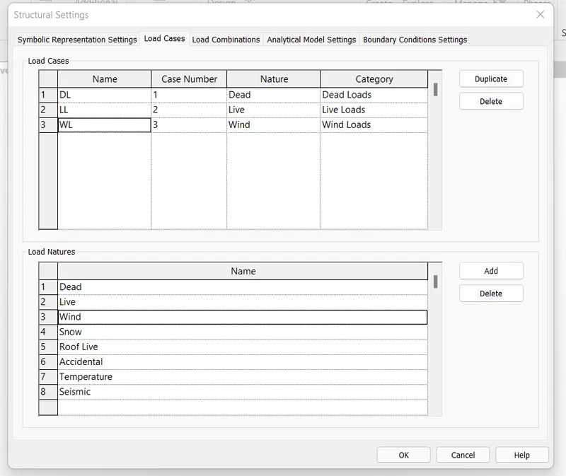
Our project is located in a residential zone containing multiple medium to high rise structures. Hence following loads are applicable to our structure based on common practice.
- Dead loads
- Live loads
- Wind loads
c. List the load combinations and include them in the analysis model
d. Analyze the building and report the following results
i. Maximum Moment in each floor for all Load Combinations
ii. Maximum Displacement in each floor for all Load combinations
iii. Lateral Displacement in building for all Lateral Load combinations
STEPWISE PROCEDURE:
- Setting up the load cases on our structural model
- Since we have already listed down the load cases and the combinations in our structural file, we have to apply the loads at particular locations.
- And to do so, just go to the analyze tab and click on the load's option.
- Then from the properties panel, assign relevant load cases be it live load, dead load, or wind load.
- After that, Scroll down within the properties panel and assign values to the loads in x, y, or z direction based on the structural preference.
- And then, select the loading method like line load, area load, hosted line or area load, etc.
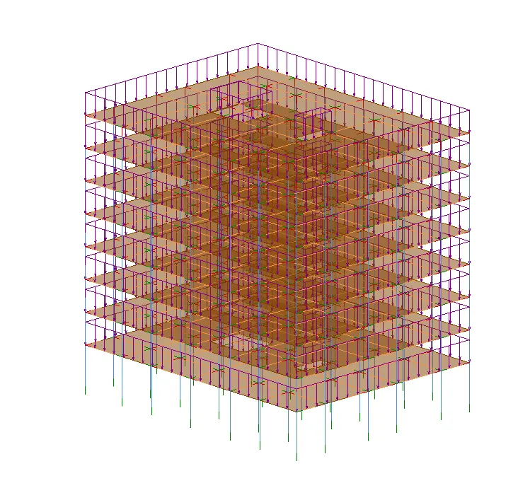
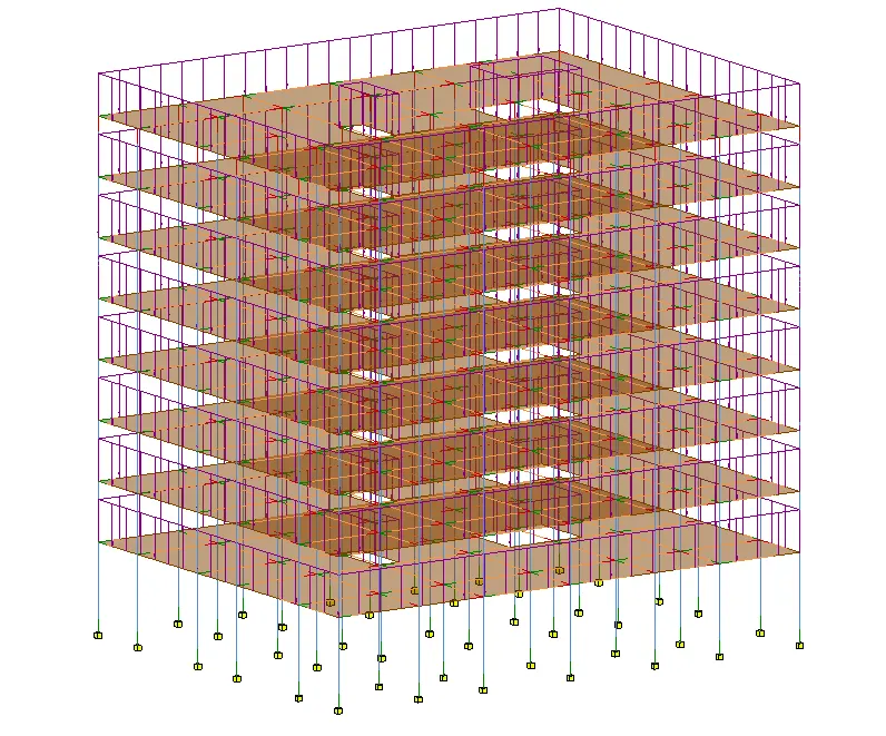
- At last, go ahead and apply all loads on each floor of the building and open up the 3d analytical model such as follows:
- Send the model to Robot Structural Analysis
- After checking up with all the load cases, combinations, and boundary conditions, our model is set to be sent for the Robot Structural Analysis.
- And for that, just go to the analyze tab and click on the add-in.
- And from the add-in, you have the link option to send your model for Robot Structural Analysis.
- Execute the calculations
- Once you have successfully linked your model as a Robot Structural Analysis file, you can run the calculations easily by clicking on the calculation button available on the RSA latest version.
- And after executing the calculations, go to the results and and generate all of the required moments, reactions, and displacements.
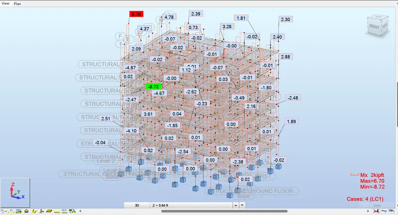
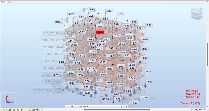
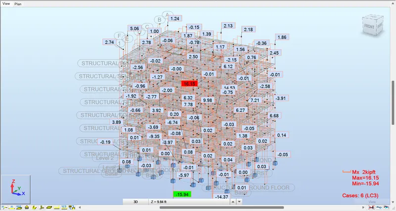
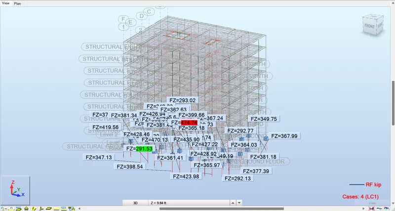
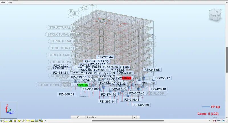
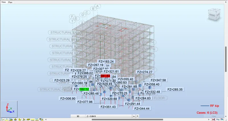
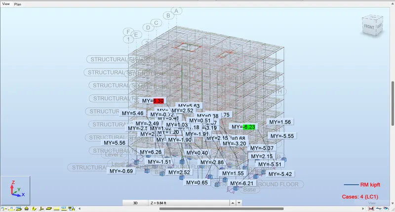
- Thus, the exact procedure was carried out and the following results were generated for our structural model from the RSA.
Maximum Moment in each floor
- LC1
- LC2
- LC3
FZ
- LC1
- LC2
- LC3
My
- LC1
- LC2
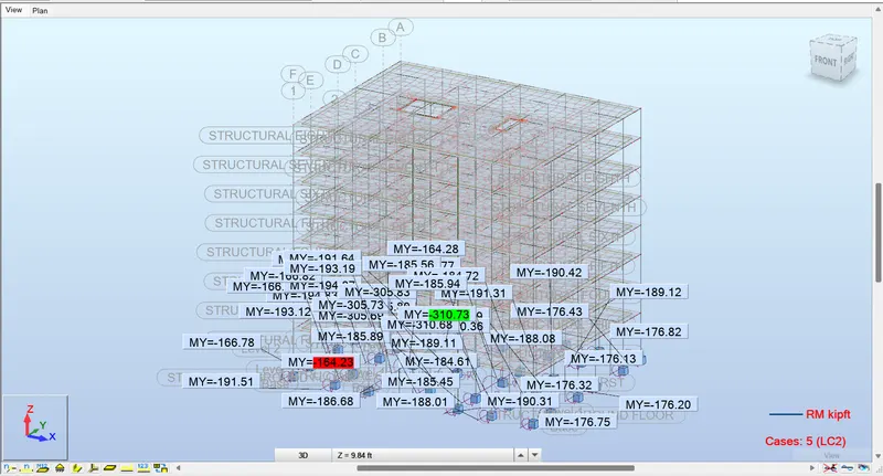
- LC3
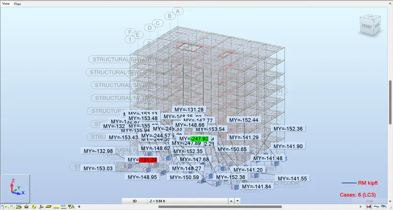
e. After analysis, do you think you have a better approach or idea in modeling structural members?
YES! proper structural analysis of the building surely projects different ideas a model can be changed for more stability and better space management.
6) What is energy analysis and why do we need to consider it while modeling in Revit?
How does the factor of sustainability improve the quality of your design?
ANSWER:
Energy analysis of the building refers to examining the expected energy consumption of the building based on its geometry and designs in order to come down to the best possible energy outcome that controls the overall energy performance of the building. Typical building structures consume huge amounts of energy in terms of electricity and fuel for their daily operations. This often leads to a negative impact on the surrounding environment. Hence, it is crucial to perform a precise energy analysis and look for the best approach possible.
Also, the rate at which the world population is growing is very concerning as we only have limited resources in terms of fossil fuels. Therefore, it is of utmost importance to look for alternatives through proper energy analysis to minimize the wastage and preserve it for the upcoming generations. And sustainable development is the only to go for it. In addition to minimizing the energy consumption of the building, sustainable development also makes the building more environment-friendly and at the same time, it also makes your designs more habitable which improves the quality of your designs in the long run.