Speed-Torque Characteristics for Frequency Control Method of Motor & determining the Stability of Motor from Motor and Load Torque Equations (Functions of Speed)
OBJECTIVES:
- To answer the question: How induction motor operation is similar to the clutch?
- To calculate the starting time of a drive with the following parameters: J=10 kg-m2 ; Tm = 15 + 0.5ωm ; Tl=5+0.6ωm
- A drive has following equations for motor and load torques:
Tm=(1+2ωm) ; Tl= 3 √ωm
Obtain the equilibrium points and determine the stability.
- To make a MATLAB script file which will plot speed-torque characteristics for frequency control method.
SOLUTIONS:
Solution to Objective 1:
The clutch is a device in an automobile which is used to connect/disconnect transmission of power from the engine flywheel to the gearbox drive shaft.
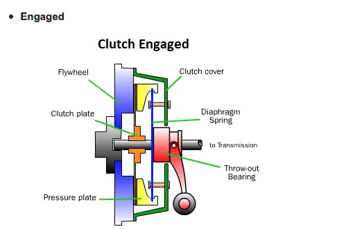
During transmission power/rotational speed from the driving shaft (connected to engine flywheel) to the driven shaft (connected to the gearbox), there are some power/energy losses in the form of heat due to which the speed from the engine flywheel is not fully transmitted to the driven shaft connected to gearbox.
This power/rotational speed losses during transmission of power/speed from the driving shaft to the driven shaft is represented by a term named ‘slip’.
ω2=ω1 (1-s)
where ω2=Speed of Driven Shaft (connected to Gearbox)
ω1=Speed of Driving Shaft (connected to Engine Flywheel)
s=slip
Similarly in an induction motor, a rotating magnetic flux is produced by the stator windings in the air gap between the stator and the rotor. This rotating magnetic field produced by the stator windings is called Synchronous Speed. An induction motor’s rotor rotates at a speed lesser than the somewhat slower than the rotating magnetic field produced by the stator. This induces an opposing current in the induction motor's rotor. The induced currents in the rotor windings in turn create magnetic fields in the rotor that react against the stator field. The direction of the magnetic field created will be such as to oppose the change in current through the rotor windings, in agreement with Lenz's Law. The cause of induced current in the rotor windings is the rotating stator magnetic field, so to oppose the change in rotor-winding currents the rotor will start to rotate in the direction of the rotating stator magnetic field. The rotor accelerates until the magnitude of induced rotor current and torque balances the applied mechanical load on the rotation of the rotor. Since rotation at synchronous speed would result in no induced rotor current, an induction motor always operates slightly slower than synchronous speed. The difference, or "slip," between actual and synchronous speed theoretically varies from 0 to 1.
Similar to the analogy depicting the speed relationship between the driven shaft and the driving shaft involving a clutch, the relationship between the synchronous speed of induction motor (rotating magnetic field speed originated from stator windings) and the rotor speed of an induction motor is as follows:
N=Ns (1-s)
where Ns=Synchronous Speed(Rotating magnetic field speed from stator windings)
N= Rotor Speed
s= slip
From the above formula and the formula depicting the relationship between engine speed and the transmitted speed to the drive wheels via a clutch, it can be concluded that:
N (Rotor speed of induction motor) corresponds to ω2 (Transmitted speed to drive wheels).
Ns (Synchronous speed of Induction Motor) corresponds to ω1 (Engine Speed).
s (Slip) in both formulas depict different things although their range still lies between 0 to 1.
Solution to Objective 2:
Given:
J=10 kg-m2 where J is the net moment of inertia comprising the motor and load.
Tm = 15 + 0.5ωm where Tm is the torque generated by the motor and ωm is the rotational speed of the motor.
Tl = 6 + 0.6ωm where Tl is the load torque and ωm is the rotational speed of the motor.
The steady state stability equation for an induction motor:
Tm – Tl = J X [dω/dt]
where dω/dt = angular acceleration of the motor.
At steady state, the operation of motor torque aligns with that of load torque:
Tl=Tm i.e.
15 + 0.5ω = 5 + 0.6ω
- ω = 100 rad/s (at steady state)
Therefore, the rotational speed of the induction motor at steady state is 100 rad/s.
Now substituting the values of steady state speed of induction motor, Tl and Tm in the steady state stability equation:
(15 + [0.5 X 100]) – (5 + [0.6 X 100]) = 10 X (dω/dt)
- (dω/dt) = (10 – 0.1ω)/10
- (dω/dt) = 1 – 0.01ω
- dt = dω/(1 - 0.01ω)
In general, Induction motor operates in the range of 1% to 5%. Let’s assume that the slip in induction motor is 2.5%. Therefore the speed of the rotor of the induction motor is 97.5 rad/s considering the slip.
Now, at initial state, t1=0, ω1 (rotational speed of rotor) = 0 rad/s.
We need to find out the time (t2) at which ω2 (rotational speed of rotor) = 97.5 rad/s.
Therefore,
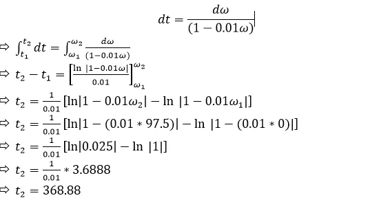
Therefore, the starting time of the drive is t2-t1=368.88-0=368.88 seconds.
Solution to Objective 3:
Given equations:
Tm = 1 + 2ωm -> Motor Torque Equation
Tl = 3√ωm -> Load Torque Equation
The stability of a motor is determined by the ability of the motor to have the required optimum power to drive the load. If the motor has the required optimum power to drive the load, then the motor is said to be stable.
Steady State Stability for an Induction Motor:
Tm – Tl = J X (dω/dt)
At steady state:
Tm = Tl
1 + 2ωm = 3√ωm
Squaring both sides:
1 + 4ωm2 + 4ωm = 9ωm
4ωm2 - 5ωm + 1 = 0
Solving for ωm :
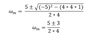
ωm = 1 or ωm = 0.25
Therefore the equilibrium points for the operating speed of the motor are 1 rad/s and 0.25 rad/s.
For the induction motor to be stable, the following condition should be satisfied:
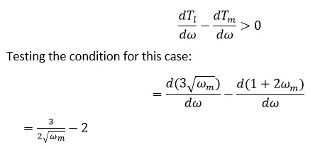
Checking the validity of the condition for the obtained equilibrium points of ωm:
ωm = 0.25
= [3/(2*√0.25)] - 2
= 1
> 0 -> Condition satisfied.
ωm = 1
= [3/(2*√1)] - 2
= 1.5 – 2
=-0.5
< 0 -> Condition not satisfied.
Therefore, the stability of induction motor for the given load is achieved at the motor speed of 0.25 rad/s.
Solution to Objective 4:
In order to plot the Speed-Torque Curve for an Induction Motor for different applied frequencies, I have defined values to different parameters required for calculating the induced torque and the motor (rotor) speed. I have defined an array of slip values (ranging from 0 to 1) and an array of applied frequencies (ranging from 0 Hz to 100 Hz). After initialising all the necessary parameters requires for calculating the motor speed and the torque induced, the formulas are defined for calculating the induced torque and the motor (rotor) speed.
And finally after obtaining a range of calculated values for induced torque and the motor speed for different applied frequencies, the commands for plotting the Torque-Speed curves for different applied frequencies are implemented.
My code for plotting the Torque-Speed Characteristics of an Induction Motor for various applied frequencies:
close all
clear
clc

%Initialising parameters required for calculating Motor Speed and Induced
%Torque
r1=0.641;
x1=1.106;
r2=0.332;
x2=0.464;
xm=26.3;
v_phase=460/sqrt(3);
P=4;

%Calculating the Thevenin Voltages and impedance from the equations:
v_th=v_phase*(xm/sqrt(r1^2 + (x1+xm)^2));
z_th=((1i*xm)*(r1+1i*x1))/(r1+1i*(x1+xm));
r_th=real(z_th);
x_th=imag(z_th);

%Declaring an array for slip values and applied frequency values:
s=linspace(0,1,50);
s(1)=0.001;
app_freq=linspace(0,100,11);

%Calculating the torque-speed characteristic for many applied frequencies to
%the stator:
for j=1:numel(app_freq)
 n_sync(j)=(120*(app_freq(j)))/P;
 w_sync(j)=(2*pi*n_sync(j))/60;
 for k=1:numel(s)
    nm(j,k)=(1-s(k))*n_sync(j);
    t_ind(j,k)=(3*(v_th)^2*r2/s(k))/(w_sync(j)*((r_th+(r2/s(k))^2+(x_th+x2)^2)));
 end
end

%Plotting the Torque-Speed characteristics:
for a=1:numel(app_freq)
    plot(nm(a,:),t_ind(a,:),'Linewidth',2)
    legendInfo{a} = ['Applied Frequency = ' num2str(app_freq(a)) ' Hz'];
    legend(legendInfo)
    hold on
end
xlabel('\bf\itn_{m} (Motor Speed in RPM)');
ylabel('\bf\tau_{ind} (Induced Torque in N.m)');
title('\bfInduction Motor Torque-Speed Characteristic');
hold off;
grid on;
Plots Obtained:
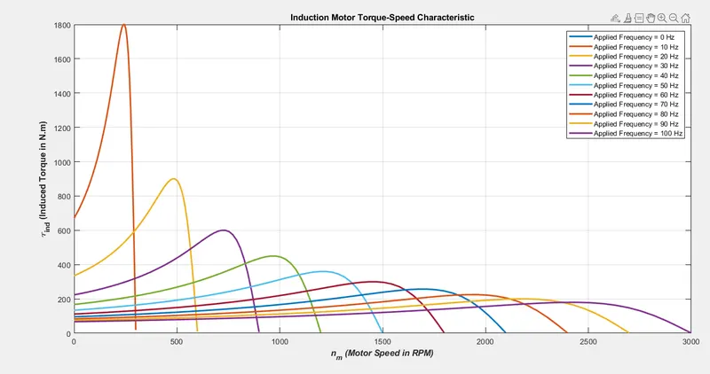
On the basis of the plots obtained, given that all the parameters remain constant, it can be concluded that:
- As applied frequency increases, the maximum Torque decreases.
- As applied frequency increases, the maximum motor speed increases which is evident as applied frequency is directly linked to the rotor speed.
- The rate at which torque increases, reaches it's maximum and decreases, is higher at lower frequencies compared to that at higher frequencies.
REFERENCES:
- Electric Machinery Fundamentals by Stephen J. Chapman
- https://skill-lync.com/knowledgebase/calculating-starting-time-for-induction-motor-3