Solar Photovoltaic Powered Electric Vehicle
CHAPTER- 1
INTRODUCTION AND LITERATURE REVIEW
1.1 GENERAL
In India fossil fuels are the main source of energy. As of now 79.58% of total energy consumption is produced by fossil fuels. Fossil fuels mainly used to produce electrical energy and as the fuel of vehicles. Burning of fossil fuels release millions of tons of pollutants into the atmosphere each year such as oxides of carbon (COx), oxides of Sulphur (SOx) and oxides of nitrogen (NOx). In all the Internal Combustion (IC) engines, burning of petroleum takes place and hence causes many environmental problems as well as biological problems.
The unsustainable nature of fossil fuel and its horrendous effect on our environment create concerns to find an environment friendly alternative energy source as dependency on fossil fuel is increasing exponentially. Quest of finding environment friendly energy source show us the alternatives of all fuel types and energy carriers types renewable energy sources like sun, wind, tides, hydropower and biomass which are safe, clean and different from fossil fuel.
All renewable energy sources are effective but solar energy is the most sustainable as our sun will provide this solar energy for another billion years. Photovoltaic cell efficiency increases every year as new ideas with new technology keeps improving every year and production of photovoltaic panels is now most than ever before, doubling its production in every two years. Now it is the fastest growing alternative energy source of all renewable energy sources. So, considering improvement in solar energy technology, growth, efficiency and effectiveness we should implement this technology as this is environment friendly and sustainable.
In last few years, lots of research have been conducted and increasing attention has been spent towards the applications of solar energy to car. Various solar car has been built and tested. Despite a significant technological effort and some spectacular outcomes, several limitations, such as low power density, energetic drawbacks, weight, fuel savings and cost, cause pure solar cars to be still far from practical feasibility.
Solar powered cars are one kind of electrical car that has solar panel on its outside and it would harness energy from the sun via solar panels. Solar panels will pass electricity to the battery and charge it then passes the electrical energy to motor which give the car driving force by converting electrical energy to mechanical energy. They are noiseless and pollution-free with no rotating parts and need minimum maintenance. So, we should look forward for a car that is safe, environment friendly, noiseless and make our everyday life whole lot easy. It is seen that the electric motor drive is more convenient for automobiles due to this type of engine that achieves a 90% efficiency (power produced / consumed energy). Instead, the combustion engine takes advantage of 40% less energy. This is because there is no loss of energy in the form of heat, vibration and partial combustion. All the energy stored in the battery can be converted into usable energy.
1.2 LITERATURE REVIEW
This section presents an overview on the literature of various studies related to solar photovoltaic powered electric vehicle. The literature presented 6 car with a direct current electric motor. The next study explains the calculations about braking force between the tire and the road and validates the forces applied to the vehicle steering system.
Phil Howlett and Peter Pudney [3]. described the performance of solar cars depends on many factors: power, aerodynamics, traction efficiency, weight, reliability, and driving strategy. The optimal driving strategy for an ideal car is essentially a speed-holding strategy. For a real car with inefficient energy storage, however, there are two distinct holding speeds. The lower speed is held when solar power is low and must be supplemented from stored energy. The upper speed is held when solar power is high, and excess energy is stored.
- Ahmed, A. H. Zenan and M. Rahman [4]. proposed economic analysis performed on the life cycle cost of solar cars, as opposed to traditional fuel-based cars shows that over the long-term, solar cars come out to be much less expensive. Over a period of 20 years, combined cost of solar component replacements and electricity charges amount to approximately 1/9th the total cost of operating a fuel-based car.
- Ashrafee, S. Morsalin and A. Rezwan [5] developed aerodynamic drag, weight, and rolling resistance all influence the car's design. Due to its simplicity and less bulkiness this design also reflects cost effectiveness and user friendliness.
Narges Taran, Vandana Rallabandi [6] axial flux permanent magnet motors are suitable options for solar powered vehicles due to their compact structure and high torque density.
A preliminary design a two-seated compact light-weight four-wheeler solar car of the electric drive system which involves estimation of the required panel size, battery capacity and motor power is carried out. The clean solar car will be beneficial to both the environment and the public who are otherwise exposed to many health problems due to toxic exhaust gases from fuel power cars. Considering the probable positive effects of different factors on the price associated with owning and using a solar car as a commuter, it can certainly be stated that in the upcoming years.
1.3 OBJECTIVES
Based on available literature review carried out and research gaps identified as discussed above, the following objectives were proposed for the present study.
- Optimal sizing of solar PV panels for the proposed work.
- Selection of battery storage system for the model.
- Selection of suitable sizing of BLDC motors for driving the system.
- Design a control strategy for a solar photovoltaic powered electric vehicle.
- Installation of motor controller for the regulation of speed.
CHAPTER 2
METHODOLOGY AND IMPLEMENTATION
2.1 INTRODUCTION
A solar vehicle or solar electric vehicle is an electric vehicle which is powered completely or significantly by direct solar energy. Usually, photovoltaic (PV) cells contained in solar panels convert the sun's energy directly into electric energy.
The basic principle of solar car is to use energy that is stored in a battery during and after charging it from a solar panel. The charged batteries are used to drive the motor which serves here as an engine and moves the vehicle in reverse or forward direction.
The main components used in the solar electrical car are,
- Solar array and power trackers
- Electric motors (Hub motors in this case)
- Speed controllers
- Battery (Lead-acid battery in this case)
- Wheels, steering system and fabrication
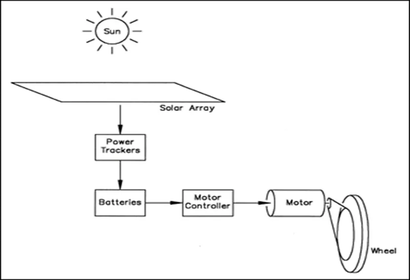
Fig. 2.1: Block Diagram Representation of a Solar Electric Car
The block diagram of working of a solar electric car is shown in figure1. Solar cars are powered by the sun's energy. The main component of a solar car is its solar array, which collect the energy from the sun and converts it into usable electrical energy. Power trackers converts the energy collected from the solar array to the proper system voltage, so that the batteries and the motor can use it. The solar cells collect a portion of the sun's energy and stores it into the batteries of the solar car. After the energy is stored in the batteries, it is available for use by the motor & motor controller to drive the car. The stored power is passed to the motor, causing the drive shaft to turn. The drive shaft causes the wheel to spin. The spinning wheel moves the car forward. The motor controller adjusts the amount of energy that flows to the motor to correspond to the throttle. The motor uses that energy to drive the wheels. At low light conditions or after dark, the consumed power rate is designed low than it can be replenished too quickly.
2.2 SOLAR PANEL
2.2.1 DESCRIPTION AND SPECIFICATIONS OF A SOLAR PANEL
Solar cells are made of silicon usually, which are specially treated to form an electric field. The backside is positively doped with boron and the negative side doped with phosphorus is exposed towards the sun. When photons of sunlight hit the solar cell, electrons are displaced from the atoms in the semiconductor material, creating electron-hole pairs. If electrical conductors are then attached to the positive and negative sides (Figure-2), an electrical circuit is formed, and the moving electrons create electric current Iph (photocurrent). Greater the intensity of sunlight, the greater is the flow of electricity.
In Solar Photovoltaic Cell (PVC) silicon crystals are laminated into n-type and p-type layers, stacked on top of each other. Light striking the crystals induces the “photovoltaic effect,” which generates electricity. The electricity produced is called Direct Current (DC) and can be used immediately or stored in a battery. On top of the vehicle is limited and suggested using superior PV cells with high efficiencies and high output currents. As a result, a significant amount of PV energy can be produced and provided to the on-board power supply of vehicles.
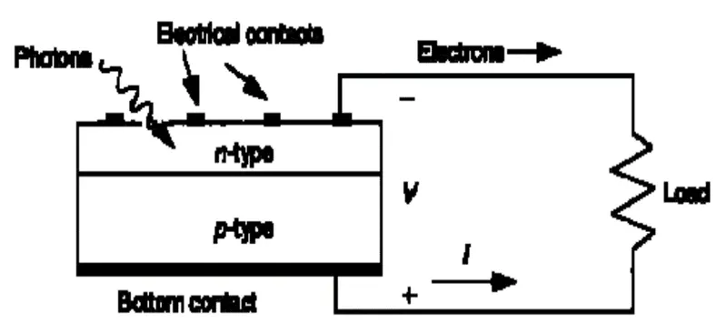
Fig. 2.2.1 (a): Photovoltaic cell exposed to sun light
There are three types of solar panels.
- Mono crystalline solar panels
- Polycrystalline solar panels
- Thin film solar panels
The panels used here are of type polycrystalline. This is because of moderate in cost and. Polycrystalline panels, sometimes referred to as multi crystalline panels, are popular among homeowners looking to install solar panels on a budget. The multiple silicon crystals in each solar cell makes it harder for electrons to flow. This crystal structure makes the efficiency rate of polycrystalline panels lower than mono crystalline panels. Polycrystalline panel efficiency ratings will typically range from 15% to 17%.
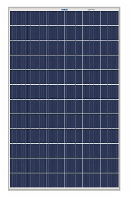
Fig. 2.2.1 (b): Polycrystalline Solar Panel
This 300W Powerhouse Polycrystalline solar panel is ideal for keeping 30 V batteries topped up. Excellent module efficiency. Advanced EVA encapsulation to give better protection to modules. Best in class conversion efficiency and antireflective coating for more light absorption. Optically, mechanically and electrically tested. Comes with high strength aluminium frame designed to offer high torsion resistance. With rated power range of 270-300 W, module voltage of 30 V and 72 number of solar cells, this solar panel provides high power output with easy installation. This solar panel is made of latest technology, which provides it tough duty extreme weather performance and makes it durable. It can be used in several applications. All the specifications of solar panel are given in the Table 2.2
Table 2.2: Specifications of solar panel
|
Rated Power Range |
270-300 W |
|
Watt |
300 W |
|
Module Voltage |
30V |
|
Module Dimension (L x W x T) |
1955 x 992 x 40 mm |
|
Weight |
23.4 kg |
|
Number of Cells |
72 |
|
Cell Dimensions |
156.75 x 156.75/6 x 12 mm |
|
Connection |
2 panels are connected in parallel |
|
Tolerance |
±3% |
|
Open Circuit Voltage, Voc |
44 V |
|
Short Circuit Current, Isc |
8.7 A |
|
Voltage at Maximum Power, Vmp |
37 V |
|
Current at Maximum Power, Imp |
8.2 A |
|
Frame Material |
Aluminum |
|
Module Efficiency |
17.80% |
|
Operating temperature range |
(-40°C to 80°C) |
2.2.2 SOLAR PANEL MODELLING
A solar cell is the building block of a photovoltaic panel. A photovoltaic panel is developed by connecting many solar cells in series and parallel. A single photovoltaic cell can be modelled by utilizing current source, diode and two resistors as shown in the figure 2.2.2 (a)
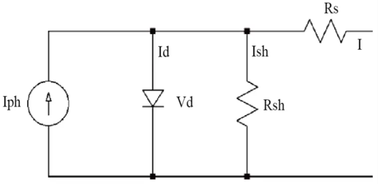
Fig.2.2.2 (a): Equivalent circuit of a single solar cell.
The equation for a photovoltaic cell is given by,
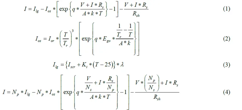
where I & V: Photovoltaic cell output current and voltage.
Ios: PV cell reverses saturation current.
T: Solar cell temperature in Celsius.
k: Boltzmann’s constant, 1.38 × 10⁻¹⁹ J/K.
q: Electron charge, 1.6 × 10⁻²³ C.
Ki: Short circuit current temperature coefficient at Iscr;
λ: Solar cell irradiation in W/m2.
Iscr: Short circuit current at 25 degrees Celsius.
Ilg: Light-generated current.
Ego: Band gap for silicon.
A: Ideality factor.
Tr: Reference temperature.
Ior: Cell saturation current at Tr.
Rsh: Shunt resistance.
Rs: Series resistance.
The photovoltaic cell operates as a constant current source at low values of operating voltages and a constant voltage source at low values of operating current.
The P-V output characteristics with varying irradiation are shown in figure 2.2.2 (b). The I-V output characteristics of PV module with varying irradiation are shown in figure2.2.2(c). When the irradiation increases, the current output increases, and the voltage output also increases. This results in net increase in output power with increase in irradiation.
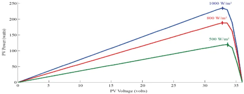
Fig 2.2.2(b): P-V characteristics of a typical PV module for varying solar irradiance.
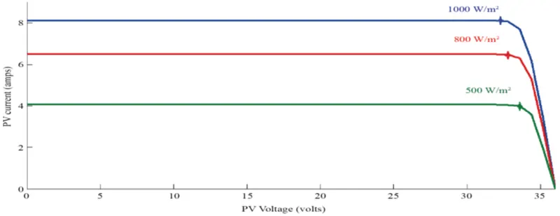
Fig. 2.2.2 (c): I-V characteristics of a typical PV module for varying solar irradiance.
2.3 BATTERY STORAGE SYSTEM
2.3.1 DESCRIPTION AND SPECIFICATIONS
A battery is a device that converts chemical energy into electrical energy and vice versa. Usually it has two terminals – Positive Cathode and Negative Anode. During potential changing (charging or discharging) the system depends upon the chemical reaction of electrolyte (liquid or paste solution). Basically, electrolyte allows the ions to flow between the two terminals (cathode and anode) or the battery active materials which allows current to flow out of the battery to perform required work.
The uses of batteries are knowing no bound. For any electronic devices that needs high energy storage capacity (electric vehicle, electric generator etc.) or for any device that needs low energy output. Battery is used for either to storage energy or to act as a power supply. Along with technological improvement the storage capacity, size, lifetime is improving also the new uses of batteries are also emerging day by day. Battery is the main power supply of a vehicle. Battery is a device that stores chemical energy and makes it available in electrical form. For our solar car we are using battery for a media to store energy to have continuous output. We have 2 types of batteries namely primary (non-rechargeable) and secondary (rechargeable). Here, secondary type battery is used. The battery used for this project is lead-acid type.
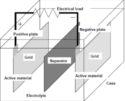
Fig.2.3.1 (a): Schematic diagram of lead acid battery
The discharging and charging of lead-acid battery is as follows
Discharging: In the discharged state both the positive and negative plates become lead(II) sulfate (PbSO4) and the electrolyte loses much of its dissolved sulfuric acid and becomes primarily water.
Negative plate reaction:
Pb(s) + HSO4 -(aq) → PbSO4(s) + H+(aq) + 2e-
Positive plate reaction:
PbO2(s) + HSO4 -(aq) + 3H+(aq) +2e-→ PbSO4(s) + 2H2O(l)
Total reaction:
Pb(s) + PbO2(s) + 2H2SO4(aq) → 2PbSO4(s) + 2H2O(l) | E0cell=2.05 V
Charging: In the fully charged state, the negative plate consists of lead, and the positive plate is lead dioxide. The electrolyte solution has a higher concentration of aqueous sulfuric acid, which stores most of the chemical energy.
State of Charge (SOC) (%)
SOC is an expression of the present battery capacity as a percentage of maximum capacity. SOC is generally calculated using current integration to determine the change in battery capacity over time. It can also be explained as
SOC= Available capacity / Nominal capacity
Depth of Discharge (DOD) (%)
The percentage of battery capacity that has been discharged expressed as a percentage of maximum capacity. DOD is actually the opposite of SOC.
If SOC, 100% then DOD 0%
0%<SOC<100% then DOD = 1 - SOC
0% & DOD 100%
Terminal Voltage (Vt)
The voltage between the battery terminals with load applied. Terminal voltage varies with SOC and discharge/charge current.
Open-circuit voltage (Voc)
The voltage between the battery terminals with no load applied. The open-circuit voltage depends on the battery state of charge, increasing with state of charge.
Table 2.3: Specifications of battery
|
Voltage |
48V |
|
Battery Capacity |
30Ah |
|
Power |
1440 W |
|
Weight |
8.5 kg |
|
Size |
195x130x155x168 mm |
|
Max Pulse Discharge Rate |
90 A |
|
Charging Current |
9 A |
|
Storage Temperature |
300 C |
|
Cycle life |
1000 |
|
Average Life |
10 Years |
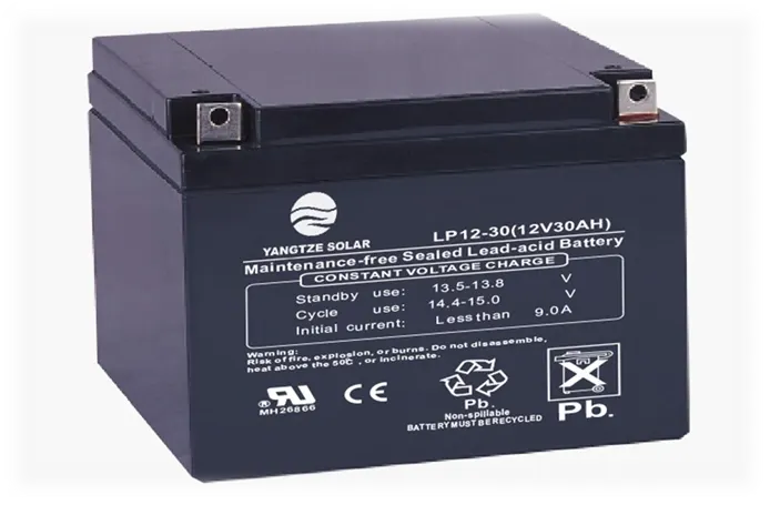
Fig. 2.3.1(b): Lead-acid battery used
2.3.2 BATTERY MODELLING
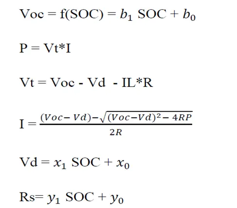
Our proposed battery model is basically Thevenin model considering the voltage across the parallel components a constant voltage Vd. Here we are following the perspective of simple battery model by considering all the parameters as constant, function of SOC (State of Charge).
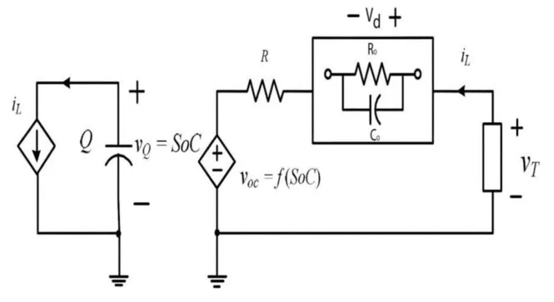
Fig. 2.3.2: Proposed battery model
Here,
2.4 BLDC GEARED MOTOR
2.4.1 DESCRIPTION AND SPECIFICATION
Motor is an electrical machine that converts electrical energy into mechanical energy. Motor works through the interaction between a motor's magnetic field and winding currents to produce rotary force that convert electricity into motion.
In electrical vehicle or solar vehicle, we normally use DC motor. Motor in an electrical vehicle requires
- Quick starts and stops rate
- Quick acceleration or deceleration
- High torque low speed hill climbing
- Low torque high speed cruising
- Wide speed range of operation
- Noiseless operation
- Good torque weight ratio
Brushless DC motor satisfies all the above constraints hence BLDC motors are used for this project.
A brushless DC electric motor, is a synchronous motor using a direct current (DC) electric power supply. It uses an electronic closed loop controller to switch DC currents to the motor windings producing magnetic fields which effectively rotate in space and which the permanent magnet rotor follows. The advantages of a brushless motor over brushed motors are high power-to-weight ratio, high speed, nearly instantaneous control of speed (rpm) and torque, high efficiency, and low maintenance. The speed can be easily controlled by varying the applied DC voltage.
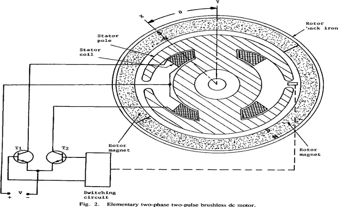
Fig 2.4.1(a): Elementary circuit of BLDC motors
Table 2.4: Specifications of BLDC motor
|
Type |
BLDC geared motor |
|
Rated Voltage |
48 Volt DC |
|
Rated Power |
1000 W |
|
No Load Current |
4.0 A |
|
No Load Speed |
516 rpm |
|
Rated Torque |
10 Nm |
|
Rated Speed |
450 rpm |
|
Rated Current |
13.4 A |
|
Efficiency |
80 % |
|
Gear Ratio |
1:6 |
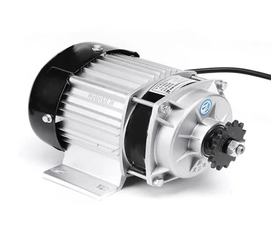
Fig. 2.4.1(b): BLDC geared motor used
2.4.2 MODELLING OF BLDC MOTOR
The equivalent circuit of BLDC Motor is as shown below.
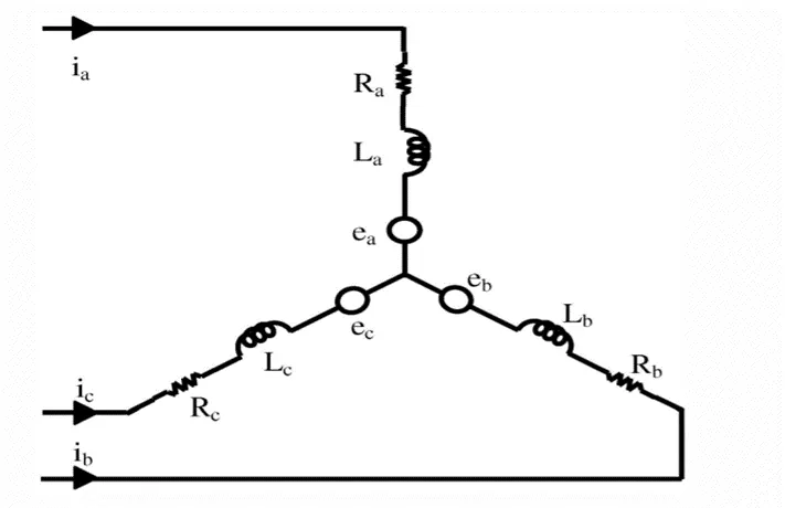
Fig 2.4.2: The equivalent circuit of BLDC Motor.
The model of the armature winding for the BLDC motor is expressed as follows:
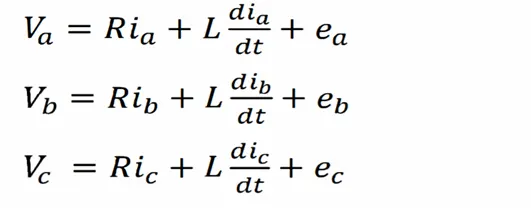
Where,
Ra = Rb = R: =R, Stator resistance per phase. [Ohm]
La = Lb= Lc=L, stator inductance per phase. [Henry]
Va, V band Vc are the stator phase voltages. [ volt]
ia, ib and ic are stator phase currents. [Ampere]
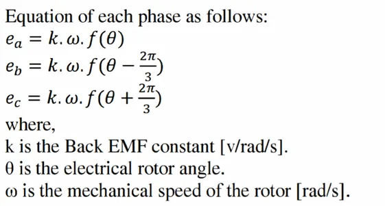
ea, eb and ec are motor Back EMFs
When BLDC motor rotates, each winding generates a voltage known as Back EMF, which opposes the main voltage supplied to the winding. The polarity of the Back EMF is opposite direction of the source voltage. It is related to the function of rotor position and each phase has 1200 phase difference. Back EMF depends mainly on three factors (i) angular velocity of the rotor, (ii) magnetic field generated by the rotor magnets, (iii) the number of turns in the stator windings.
2.5 MOTOR SPEED CONTROLLER
A motor controller is a device or group of devices that can coordinate in a predetermined manner the performance of an electric motor. It is used for regulating the speed by regulating the voltage, regulating the torque, and protecting against overloads etc. Motor controllers may use electromechanical switching and power electronics devices to regulate the speed and direction of a motor.
The accelerator pad is connected to this controller. As the throttle is pressed gradually, the voltage applied across the motor terminals of the motor also increases gradually. Hence the motor rpm and vehicle speed increases. When the throttle is released, the voltage across the motor terminals decreases. Hence motor rpm and vehicle speed decreases.
Table 2.5: Specifications of motor speed controller
|
parameters |
Minimum value |
Typical value |
Maximum value |
|
Voltage (V) |
0 |
36 |
60 |
|
Current (A) |
0 |
10 |
40 |
|
Speed control (rpm) |
0 |
3000 |
50000 |
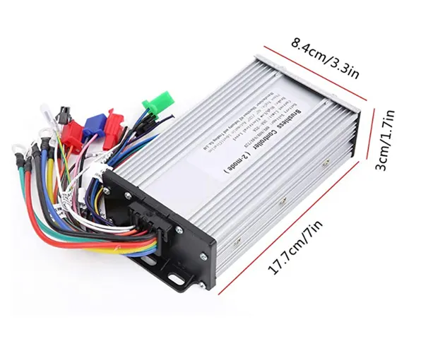
Fig 2.5: Motor speed controller used
2.6 CHAIN DRIVE SYSTEM
Chain drive is a way of transmitting mechanical power from one place to another. It is often used to convey power to the wheels of a vehicle. The geared shaft of motor drives the sprocket which is mounted with wheels. Driving and driven sprockets are connected by chain. When the driving gear is turned, it pulls the chain putting mechanical force into the system and it rotates driven gear. Chain drive has less slip than belt drives so, this is more economical and energy saving drive system.
Table 2.6: Specifications of chain drive used
|
Material of chain |
Iron |
|
Number of teeth on driving sprocket |
50 |
|
Number of teeth on driven sprocket |
40 |

Fig. 2.6: Chain drive used
2.7 POWER CALCULATION OF MOTOR
Power needed to drive a car can be determined by combining the force that acting on the car causes it to move at car speed at which this driving force must be sustained. Drive force that moves the vehicle generated by drive torque which acts wheel of the car to move it. At the design stage it's easier to frame the calculation around this drive force rather than the drive torque. Thus, the calculations in this section start by determining the size of this drive force and given a set of speed at which the vehicle should move, the drive power is found.
The total drive force that has to act on the vehicle to make it move (or keep it moving) can be estimated by adding together individual force components that arise from different physical effects. These are
- The rolling resistance force
- Aerodynamic drag force
- Force of acceleration
2.7.1 THE ROLLING RESISTANCE FORCE
Force that resists the motion when a vehicle rolls on a surface is called rolling resistance force. Wheel diameter, speed, load on the wheels etc. also contribute in the rolling resistance force
FROLLING = μR * W (17)
Here,
W= the weight of the car.
μR = the coefficient of rolling resistance.
μR is a constant that depends on the type of tires of the vehicle and the surface on which it will roll. Thicker tires with wider treads, although good for adhesion, however, produce more rolling resistance.
To conserve power solar cars, need to use thinner tires. Also, harder surfaces offer lower rolling resistance force than softer ones. Some standard values are shown as follows:
Table 2.7: Coefficient of Rolling Resistance μR of different wheels/surface
|
μR |
Description |
|
0.0003 to 0.0004 |
Pure rolling resistance Railroad steel wheel on steel rail |
|
0.0010 to 0.0024 |
Railroad steel wheel on steel rail. Passenger rail car about 0.0020 |
|
0.001 to 0.0015 |
Hardened steel ball bearings on steel |
|
0.0022 to 0.005 |
Production bicycle tires at 120 psi (8.3 bar) and 50 km/h (31 mph), measured on rollers |
|
0.0045 to 0.008 |
Large truck (Semi) tires |
|
0.010 to 0.015 |
Ordinary car tires on concrete |
|
0.0385 to 0.073 |
Stagecoach (19th century) on dirt road. Soft snow on road for worst case. |
|
0.3 |
Ordinary car tires on sand |
2.7.2 AERODYNAMIC DRAG FORCE
The force that prevents the vehicle from moving through air is called aerodynamic drag force. The aerodynamic drag force can be expressed as,
FDRAG = (1/2) * Cd * Across * ρ * (𝑉2) (18)
Here,
Cd = the coefficient of drag of the vehicle, across is its frontal area in square feet.
ρ = a constant that accounts for the air mass density
V = the vehicle’s speed.
To minimize drag for any given Cd, the coefficient of drag, and across, its frontal area must be minimized.
The drag force becomes increasingly noticeable at speeds of above 40 km/h due to it being proportional to the square of the speed. Because batteries provide only 1% as much power per weight as gasoline, optimizing for either high-speed or long-range performance goals, requires that one keeps this critical performance factor foremost in mind.
2.7.3 FORCE OF ACCELERATION
The force of acceleration should be only accounted for when the car is accelerating and is given by newton’s 2nd law of motion
FACCELERATION = m * a (19)
Where m is the mass of the car and a is the acceleration
2.7.4 TOTAL FORCE
Equations from 17, 18, 19
FT = FROLLING + FDRAG + FACCELERATION
= (μR ∗ W) + (1/2 ∗ Cd ∗ Across ∗ ρ ∗ 𝑉2) + (𝑚 ∗ 𝑎) (20)
When the car runs at constant speed, there is no acceleration, so the equation of the total force becomes
FT = FROLLING + FDRAG
= (μR ∗ W) + (1/2 ∗ Cd ∗ Across ∗ ρ ∗ 𝑉2) (21)
The power needed to be supplied by the motor in order to provide the current speed and acceleration will therefore be,
W = mg (22)
Here,
m = Mass of the car
g = gravitational constant
v = at
PT = FT ∗ v
= (μR ∗ m ∗ g ∗ a ∗ t) + (1/2 ∗ Cd ∗ Across ∗ ρ ∗ a3 ∗ t3) + (m ∗ a2 ∗ t) (23)
And at constant velocity,
PT = (μR ∗ m ∗ g ∗ a ∗ t) + (1/2 ∗ Cd ∗ Across ∗ ρ ∗ a3 ∗ t3) (24)
2.7.5 Steps involved in power calculation at different speed
Step 1:
Get the required parameters of the car
- Mass of the car, m
- Frontal area of the car, ACROSS
- Air density, 𝜌
- Rolling resistance coefficient, μR
- Drag coefficient of the vehicle. CD
Step 2:
- Maximum velocity of the car, Vmax
- Time to reach maximum velocity, tmax
- Velocities in which the car runs, v
- Time ranges of the velocities, t
Step 3:
- Acceleration, a = Vmax/tmax
- Distance covered at different speed, s = v*t
- Rise time at different speed, tr = v/a
- Fall time at different speed, tf = tr/2
- Constant velocity time, tc = t – tr -tf
Step 4:
- Get the current time, ti
- If ti is in the rise time range, Power = (μR ∗ m ∗ g ∗ a ∗ t) + (1/2 ∗ Cd ∗ Across ∗ ρ ∗ a3 ∗ t3) + (m ∗ a2 ∗t)
- If ti is in the constant velocity time, tc, Power = (μR ∗ m ∗ g ∗ a ∗ t) + (1/2 ∗ Cd ∗ Across ∗ ρ ∗ a3 ∗ t3)
- If ti is in the fall time range, Power = 0
CHAPTER 3
RESULT AND DISCUSSION
3.1 VEHICLE DESCRIPTION AND SPECIFICATIONS
All the components like solar panels, lead acid battery, BLDC geared motor are tested individually before installing to the vehicle. The design of solar electric vehicle is done and running of the vehicle is successfully completed. The performance analysis of the vehicle is carried out. This analysis is under different conditions like performance with and without load, at plane road and inclined road, under bright sunlight and under dull sunlight, with different throttle range etc. All the test results are in positive path. The model of solar vehicle is shown below.
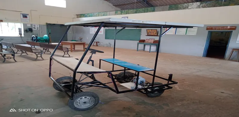
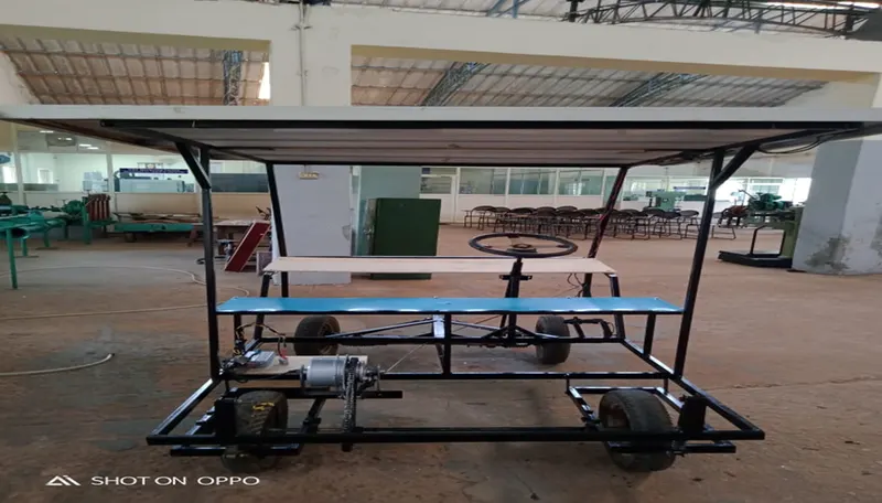
Fig.3.1: Implemented solar electric vehicle
Table 3.1: Specification of vehicle
|
Voltage |
48 V |
|
Charging current |
10 A |
|
Range |
30 kms/charge 1.5unit consumption |
|
Maximum no load speed |
468 rpm |
|
Maximum torque |
10 Nm |
|
Efficiency |
75 % |
|
Turning radius |
300 |
|
Wheel to wheel distance |
Front 1.3716m and Rear 1.524m |
|
Steering wheel |
12 inches |
|
Gears |
Single gear |
|
Tyres |
10 inches (4 in no.) |
|
Size (l*b*h) |
(1.8288*1.2192*1.8288) m |
|
Total weight |
140 kg |
3.2 Speed at different levels of throttle
It has been observed that as the throttle is increased gradually, the rpm also increases gradually. 4 levels of throttle are applied for the analysis of response. 25%, 50%, 75%, 100% are the 4 levels of throttle. This is done for both with load and without load. Here 2 persons are considered as load who are sitting in the vehicle. The plot is shown below. The obtained results in terms of speed in rpm vs % of throttle applied, Speed in kmph vs % of throttle applied and torque speed curve of electric vehicle are shown below.
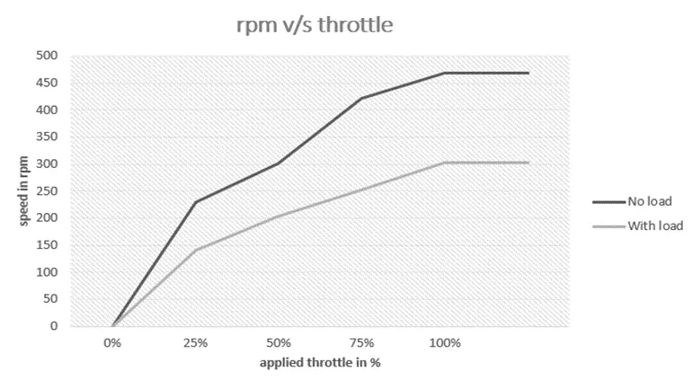
Fig. 3.2.1 Speed in rpm vs % of throttle applied
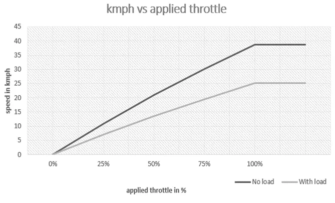
Fig 3.2.2 Speed in kmph vs % of throttle applied
3.3 Torque speed characteristics
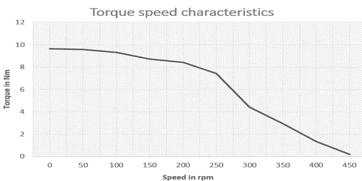
Fig.3.3: Torque speed curve of electric vehicle
Based on results the electrical vehicle has high torque at low rpm. This is called instantaneous torque. Because of this nature, the initial acceleration of the vehicle is high. As the rpm increases, the torque remains constant and after a point it starts decreasing. This decrease in torque at high rpm is because of back emf of the motor used. Hence the electrical vehicle has best performance in midrange speed.
3.4 CHARGING VOLTAGE ANALYSIS
The only source of energy for this vehicle is solar energy hence the solar irradiance plats a vital role in charging of vehicle. The availability of solar radiation in a day during every hour is observed and plotted. In this case solar radiation of a rainy day is considered. And the value changes for summer and winter seasons.
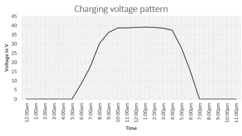
Fig. 3.4: Hourly solar radiation of a day
From the above figure we can observe that, the voltage is maximum during 10am to 4pm and is 0 during 7pm to 5 am. Hence charging the vehicle during peak sunshine hours can be useful.
3.5 PERFORMANCE CHARACTERISTICS OF A MODEL ON INCLINED ROAD
Vehicles need to be good to climb inclined roads easily. To climb the uphill, vehicle requires more torque. As this model is of less capacity it cannot climb certain uphill of more than 250. When the vehicle going downhill, inclination angle does not matter because of no stress involved. The characteristics of vehicle in inclined road is as shown in figure below.
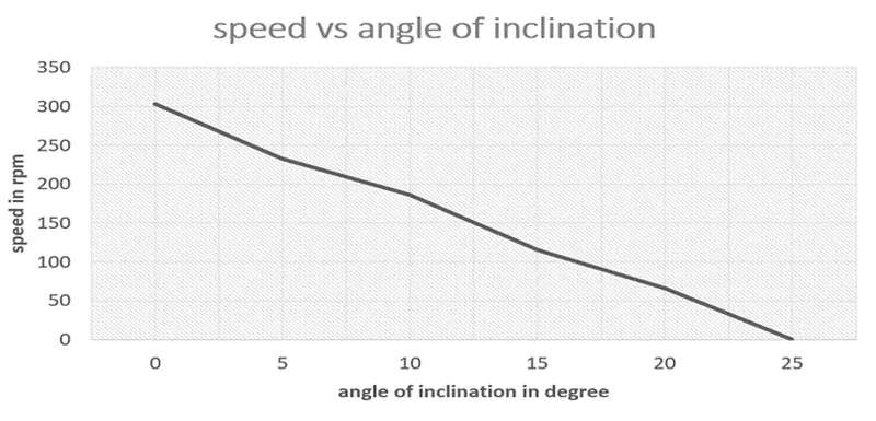
Fig. 3.5: Speed in rpm vs angle of inclination in degree
From this figure we can observe that as the inclination angle increases, speed decreases and if the angle is more than 250, vehicle comes to stop.
3.6 POWER AT DIFFERENT SPEED
The power of the vehicle increases gradually with speed of the vehicle. The power is maximum at maximum speed. It is plotted and shown as shown below.
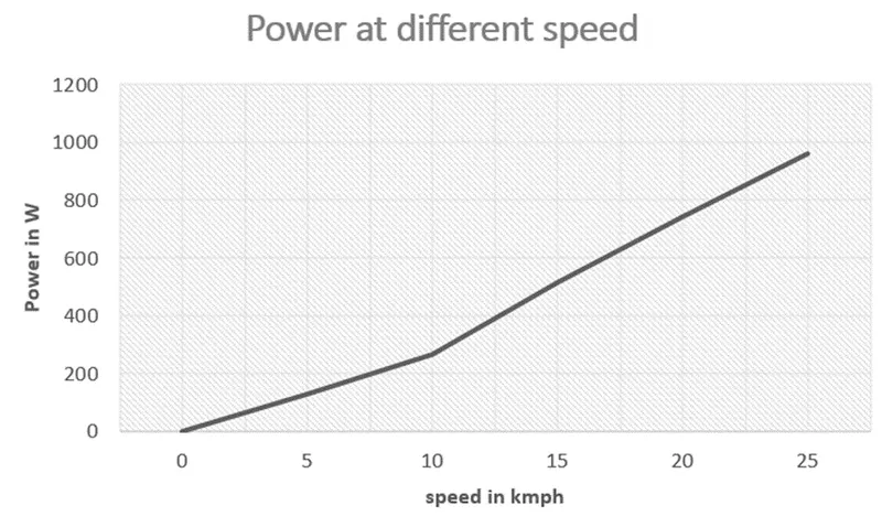
Fig. 3.6: Power at different speed
CHAPTER 4
CONCLUSIONS AND FUTURE SCOPE OF THE STUDY
The present study was to develop a green car technology that car manufactures will be able to save energy. The developed model applied control strategy for a solar photovoltaic powered electric vehicle, since developed model of a small solar car, it will help only to examine the technical aspects of the solar car technology. Based on the study carried out, the following conclusions are drawn;
The electrical vehicle has high initial acceleration because of high torque at low speed. As the vehicle attains speed, the torque decreases gradually because of back EMF of the motor. To overcome the back EMF, the power drawn increases with increase in the speed. The inclination of road makes the vehicle to struggle and draws more power to climb the inclination. New inventions in battery technology should be done which allows the batteries to charge quickly. BY this the problem of lack of power can be sorted out by using motors of higher rating and the solar panels of higher efficiency.
This model provides a clear understanding about the things to keep in mind, scope and obstacles while designing a solar electric vehicle.
It concludes that if there is a suitable decadence charging time and slot available for the solar powered electric vehicles, it can be charged by own as the vehicle which we designed does. This can be implemented in a large scale so that cost of production reduces and reaches to the people of every tier.
REFERENCES
[1]. Riisnaes, A., Allen, C., & Winkler, P. (1996). “Dakota Sun” - the next generation solar powered racing
vehicle. IEEE Aerospace and Electronic Systems Magazine, 11(11)
[2] Veracruz” by Verónica Flores “Solar Vehicles Design for Urban Use: Case Adapted to Cuitláhuac
Sánchez, 2013
[3]. P. Howlett, P. Pudney, T. Tarnopolskaya, and D. Gates, ``Optimal driving strategy for a solar car on a
level road,'' IMA J. Manage. Math., vol. 8
[4]. S. Ahmed, A. H. Zenan and M. Rahman, "A two-seater light-weight solar powered clean car: Preliminary
design and economic analysis," 2014 ICDRET, Dhaka, Bangladesh.
[5]. F. Ashrafee, S. Morsalin and A. Rezwan, "Design and fabrication of a solar powered toy car," 2014
International journal on Electrical Engineering Technology, Dhaka, Bangladesh.
[6]. N. Taran, V. Rallabandi, G. Heins and D. M. Ionel, "Coreless and Conventional Axial Flux Permanent
Magnet Motors for Solar Cars," in IEEE Transactions on Industry Applications, vol. 54, Nov.-Dec. 2018
[7]. A. Ali, D. Raisz, K. Mahmoud and M. Lehtonen, "Optimal Placement and Sizing of Uncertain PVs Considering Stochastic Nature of PEVs," in IEEE Transactions on Sustainable Energy, vol. 11, no. 3, pp. 1647-1656, July 2020.
[8]. T. Wang, D. O’Neill and H. Kamath, "Dynamic Control and Optimization of Distributed Energy Resources in a Microgrid," in IEEE Transactions on Smart Grid, vol. 6, no. 6, pp. 2884-2894, Nov. 2015.
[9]. Hiroshi Shimizu, Junji Harada, Colby Bland, Kiyomoto Kawakami, and Lam Chan Advanced Concepts in Electric Vehicle Design IEEE transactions on industrial electronics, VOL. 44, NO. 1, FEBRUARY 1997.