Sketch a G+1 residential plan according to Vaastu Shastra and Calculation of Loads as per IS code
Project on G+1 Floor residential plan
Sketch a G+1 floor residential plan, according to Vaastu shastra & list down the names of the structural drawings required to be provided to the site for construction. Also assume the sizes of the structural elements (Column, beam, slab etc) & accordingly calculate the individual corresponding loads from the members as per IS code.
Ans:
Aim: To sketch a G+1 floor residential plan according to Vaastu shastra and to calculate the individual corresponding loads from the structural members as per IS Codes.
Introduction:
Vaastu shastra: is an ancient Indian science of architecture & acts as a guide to design your home in the way that enhance positive energy. A good home needs to radiate the right kind of energy. Vaastu shastra profounds suck theories based on directions, architectures, astronomy & even astrology.
The significance of eight directions that are 4 cardinal directions namely North, South, East & West and 4 inter cardinal directions North-East, North-West, South-East, South-West. Each direction signifies an aspect of life & is governed by various gods.
- North for wealth
- South for Dharma
- West & East for overall prosperity
Loading on a structure:
The basic requirements for designing a building are,
- Selection of good structural system to resist gravity, wind & seismic forces
- Proper analysis & design
- Good detailing
- Quality construction maintaining
To consider the loads acting on a structure, Indian Standards have provided codes to refer the Dead load, live load, wind & seismic loads acting a structure according to topography, height & class of structure etc. Some of the IS codes are:
- IS 875:1987, part 1 – for dead load
- IS 875:1987, part 2 – for dead load
- IS 875:1987, part 3 – for wind load
- IS 1893:2016, part 1 – for seismic load
- IS 13920:1993 for seismic detailing
AutoCAD 2D: AutoCAD is a commercial Automatic Computer-Aided Design (CAD) and drafting software application for 2D CAD and 3D CAD drawing model, drafting and engineering drawing. It is developed and marketed by Autodesk.
Floor plan:
A Floor plan is a technical drawing to scale, showing a view from above, of the relationships between rooms, spaces, traffic patterns and other physical features at one level of a structure. Dimensions are usually drawn between the walls to specify room sizes and wall lengths. A typical Floor plan is not a top view or bird’s eye view. It is a measured drawing to scale of the layout of a floor in a building. A top view or bird’s eye view does not show an orthogonally projected plane cut at the typical four-foot height above the floor level whereas a Floor Plan could show. A floor plan is essentially a simple diagram showing room layout and offering a conceptual starting point. A floor plan is the place to begin creating and diagramming a logical space based on end user requirements.
Procedure:
Step 1: Drafting G+1 floor plan
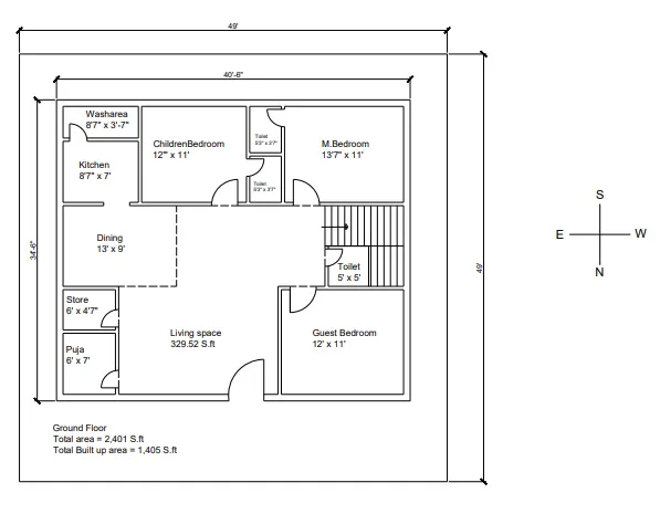
Considering total site area of 2,401 S. ft with dimensions 49’x49’ facing north direction. According to Vaastu shastra, a typical G+1 floor plan is drafted by considering basic rules.
Following are the rooms plotted in the floor plan.
- Entrance if provided at North direction facing north which implies way to victory & progress in life.
- Living space facing North consisting of 329.5 S. ft.
- Master bed room placed at South-West corner with 13’7” x 11’ which brings good health & prosperity.
- Children bed room placed at south, facing North besides the master bedroom where, attached toilets are in between the 2 bedrooms with size of 12’x11’.
- Kitchen is placed at South-East corner along wash area.
- Dining is of size 13’ x 9’.
- Guest bedroom is provided at North-West corner of the house with 12’x11’.
- Pooja room is provided in North-East corner with 6’x7’.
- Store is provided besides pooja room with 6’x4’7”.
- Staircase is provided at west direction & a common toilet is provided below the staircase.
Total ground floor built-up area = 1,405 S. ft.
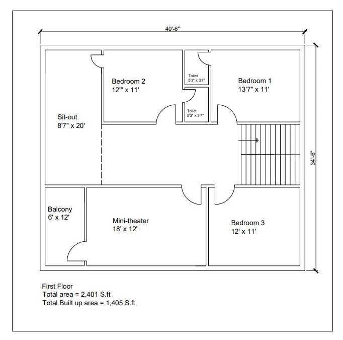
- In the first floor, 3 bedrooms, one mini-theatre is provided with a balcony and a sit-out area is provided.
- Bedroom sizes are of same as ground floor.
- Mini-theatre size is 18’x12’.
- Sit-out area is 8’7”x20’ & balcony with 6’x12’.
Typical ground floor plan
Typical First floor plan
Step 2: Structural elements measurements
Each Floor height = 3.5 meters.
Total height of the building = 8 meters (Including parapet wall of 1 meter)
Columns are provided at each corner of same dimension = 0.3x0.3x3.5m
Beams size = 0.3x0.45
Considering Red brick masonry for the construction.
Slab thickness = 0.15m.
Slab dimensions = 40’6” x 36’6”
Step 3: Calculation of Dead load
Unit weight for RCC structural element = 25 KN/m3
Dead load of each column = 0.3*0.3*7*25 = 15.75 KN.
Dead load of beam = 0.3*0.45*25 = 3.375 KN/m
Dead load of slab = 12.3*11.15*0.15*25 = 514.29 KN. (for one slab)
For two slabs = 514.29*2 = 1028.58 KN.
Considering Brick masonry with,
External wall thickness = 0.23m
Internal wall thickness = 0.11m
Dead load of External walls = 0.23*8*20 = 36.8 KN/m
Dead load of Internal walls = 0.11*7*20 = 15.4 KN/m
Step 4: Calculation of Live load
According to Table 1 of IS 875:1987 part 2, live loads for each type of building is given and for rooms as well. Considering the loads are applied uniformly and not concentrated load, live loads are as follows.
Live load for All rooms & Kitchen = 2.0 KN/m2
Live load for bathrooms = 2.0 KN/m2
For corridors, passages, staircases and store rooms = 3.0 KN/m2
For balconies = 3.0 KN/m2
Live load for 6 bedrooms = 2. KN/m2
For staircase = 3.0 KN/m2
For kitchen, puja, dining, living space = 2.0 KN/m2
For balcony, sit-out area & mini theatre = 3.0 KN/m2
For bathrooms = 2.0 KN/m2
For corridor in first floor = 3.0 KN/m2
Step 5: Calculation of Wind load
According to IS 875:2015, part 3, clause 6.3,
Wind speed may be taken as constant up to a height of 10m. However, pressures for buildings less than 10m high may be reduced by 20 percent for evaluating stability & design of the framing.
The house is considered to be in Vijayawada.
The design wind pressure Pz = 0.6*Vz2
Vz = Vb *k1*k2*k3*k4
Vb = basic wind speed from Figure 1 of IS 875:2015, part 3
Vb = 47 m/s
Risk coefficient K1 = 1.0 from table 1, IS 875, part 3
Terrain coefficient K2 = 1.0 from table2, IS 875, part 3
Topography factor K3 = 1.0 from Clause 6.3.3.1, IS 875, part 3
Importance factor K4 = 1.0, clause 6.3.4, IS 875, part 3
Therefore, Vz = 47*1.0*1.0*1.0*1.0
Design wind speed Vz = 47 m/s
The design wind pressure Pz = 0.6*(47)2
Pz = 1325.4 N/m2
Whereas the height of the building is less than 10m, the wind pressure for this building can be reduced by 20% for evaluating stability and design of the framing. (IS 875:2015, part 3, clause 6.3, NOTE)
Therefore, Pz = 1325.4-(20/100)*1325.4
So, the design wind pressure Pz = 1060 N/m2.
List of Drawings that are to be provided at construction site:
- Centre line drawing
- Footing & column layout with reinforcement details
- Column schedule with reinforcing details
- Plinth beam layout with steel details
- First floor beam layout with steel details
- First floor slab layout with steel details
- Lift pit & headroom reinforcement details.
Result:
The typical floor plan for G+1 building with stipulated dimensions is obtained by following Vaastu shastra and according to conditions. AutoCAD 2D is used to draft the floor plans. Considering the IS code books, dead loads, live loads & wind loads are calculated by assuming the dimensions of the structural elements.
The important drawings required to the construction site are listed in detail.
Conclusion:
For any design, Engineer’s knowledge is also required along with Vaastu to draft a floor plan for any type of building. For every floor plan, modifications as per Vaastu and as per one’s wish may be changed accordingly. It may not be possible every time at every place to completely follow Vaastu according to the particular site conditions.