Creating Kitchen layout, Hatching of Architectural elements and sectional view of an Industrial Building in AutoCad
Week 9 - Challenge 9
Creating Elevation, kitchen layout, sectional view of industrial building
Aim:
To create Kitchen layout, elevation view for residential building and sectional view for industrial building using AutoCAD 2D.
Introduction:
To create the elevation & sectional views, construction views are mostly used to get the reference lines perfectly. Here, in this challenge, the to draft the elevation view of residential building, floor plan is taken as external reference file to current drawing file. The reference images are also taken as external reference to draft with ease.
Hatching is one of the exciting features in AutoCAD to draft, to differentiate various materials, to express in an easier way to understand. Here in this challenge, hatching is used in all the 3 models for different purpose.
Procedure:
- To draft Kitchen Layout
- Initially units are set to decimal and millimetres using UN command.
- Limits are set using LIMMAX and LIMITS command.
- Layers are been created as dimension, text for drafting.
- Using line command, kitchen outline is first drafted, then using offset command the cabins are created.
- Fillet, offset and trim commands are most used to create the cabins in the kitchen layout.
- After the drafting is completed, in the dimensions layer, dimensions are created and modified using dimension style manager.
- Using HATCH command, the required portions are hatched.
- Text is created in text layer using singly and multi-line text command.
- The final kitchen layout is drafted using AutoCAD 2D.
- To draft the Elevation for residential building
- Initially units are set to decimal and millimetres using UN command.
- Limits are set using LIMMAX and LIMITS command.
- The floor plan was drafted earlier and now we use that as external reference to draft the elevation for that floor plan.
- Using XREF command, the floor plan is obtained in the current drawing.
- Now, using construction line, the required portions for windows, walls, doors are drafted.
- Windows are drafted using OFFSET, TRIM, COPY commands etc.
- One each is created and then copied to required positions using COPY command.
- Then the unnecessary lines are trimmed and deleted to obtain final elevation view for the residential building.
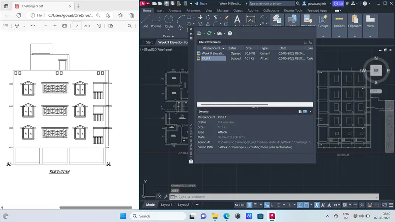
USING XREF
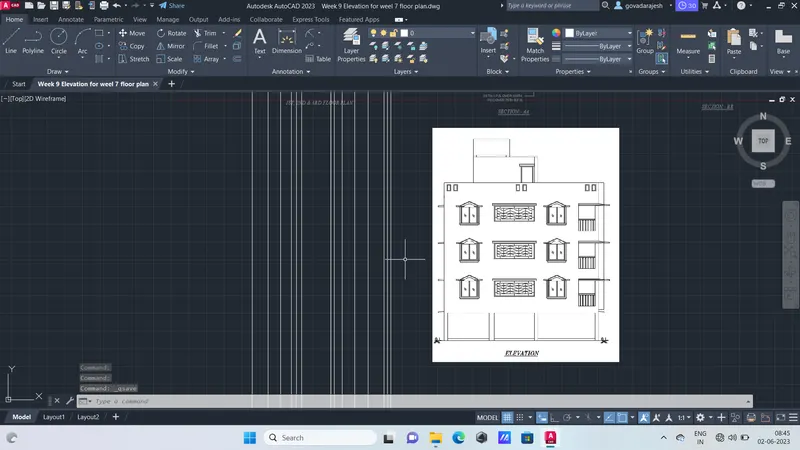
Using Construction line
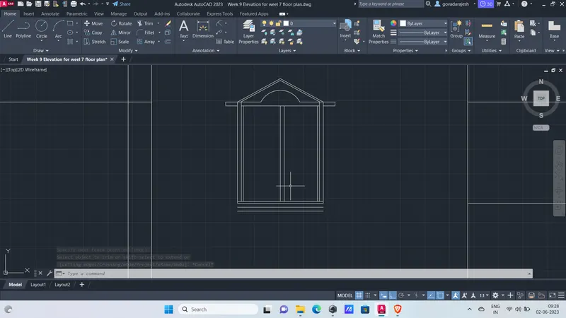
Using Offset,Trim,copy commands
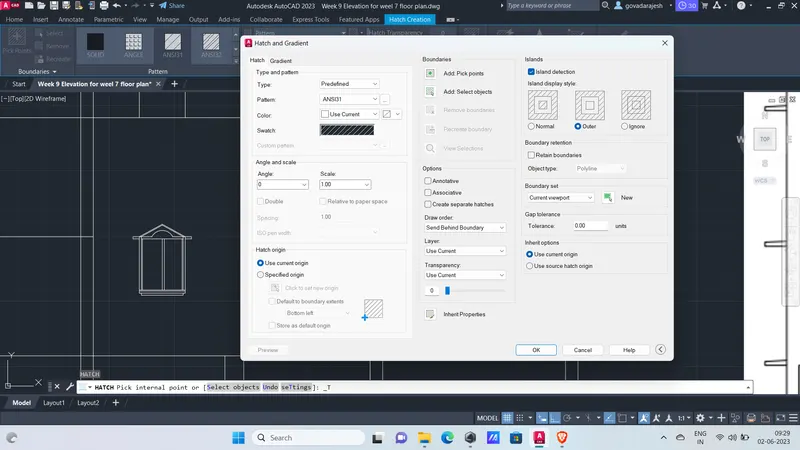
Using Hatch Edit
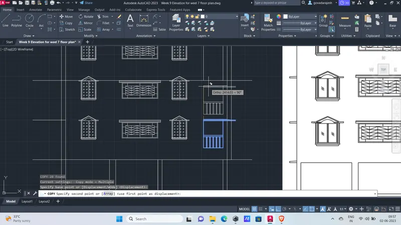
Using Copy
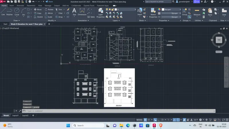
Final output
- Section view for industrial building
- Initially units are set to decimal and millimetres using UN command.
- Limits are set using LIMMAX and LIMITS command.
- For the required view, the picture is taken as external reference using XREF command to the current drawing.
- Using construction line, reference lines are drafted and then using offset command, the required portions are drafted.
- Using HATCH command, the required portions are hatched as concrete fill.
- Using DIMSTYLE command, dimensions are modified and drafted.
- Using MLEADER, the levels are denoted and are modified as per requirements.
- Using Single & multi-line text, annotations are drafted.
- Using LT for line types, dashed line is loaded and is used.
- The final sectional view for industrial building is drafted using AutoCAD 2D.
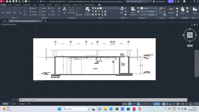
Using Xref for picture
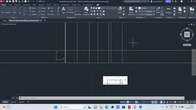
Using Construction line
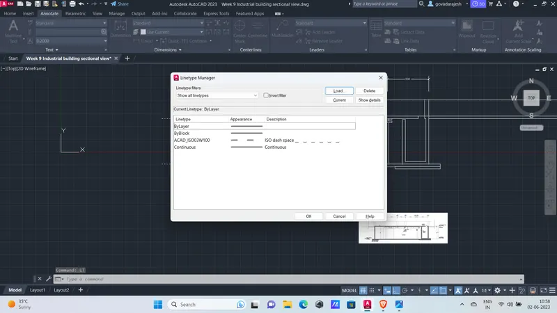
line type
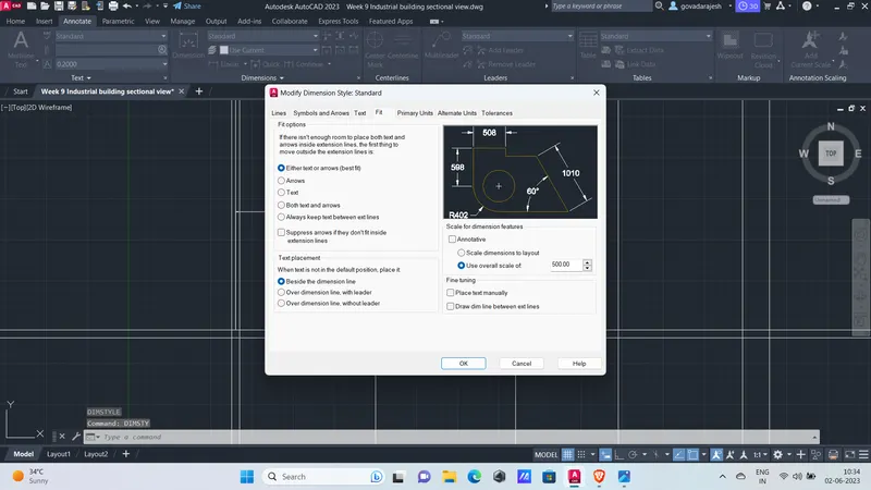
Dimension style manager
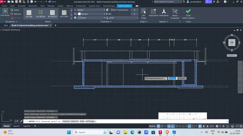
Hatching
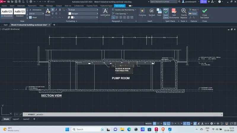
Multiline text
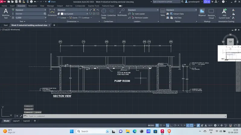
Final output
Result:
The required kitchen layout, elevation for residential building and sectional view for industrial building is drafted using AutoCAD 2D.