Sketch a G+1 residential plan according to Vaastu Shastra and Calculation of Loads as per IS code
CHALLENGE-10
PROJECT ON PLANNING AND LOAD CALCULATION FOR A G+1 RESIDENTIAL BUILDING
PREPARED BY- MEGHA GUPTA
Sketch a G+1 floor residential plan, according to Vaastu Shastra, and list down the names of the structural drawings required to be provided to the sire for construction.
Also, assume the size of the structural elements (column, beam, slab etc) and accordingly calculate the individual corresponding loads from the members as per IS code.
Aim: Aim of the project is to create a plan for a G+1 storey residential building following Vaastu Shastra and then calculating loads for structural elements as per IS code.
Introduction: Vaastu Shastra which is an ancient Indian science of architecture and acts as a guideline to design a home in the way that enhances positive energy. The nature is a powerhouse of various energy sources like sun, moon, wind, water, earth and fire. Effect of sunrays, flow of winds, pull of magnetic field of earth and other cosmic energies are considered in this science. Proper flow of energy needs to be maintained so that a house will radiate the kind of energy. Vaastu shastra includes some basic principles following which the planning of any building is done. In current project, plan of a residential building has been prepared following the following principles:
Basic principles of Vaastu Shastra:
- According to Vaastu shastra each direction signifies an aspect of life i.e. North direction is for wealth, south direction is for dharma whereas East and West directions are for overall prosperity.
- All the rooms must be in square or rectangular shapes.
- All the rooms must be airy, well lit, bright and clean.
- Centre of the house should be a space which is kept empty.
- Heavy furniture should be kept in the south-west direction.
- Plants and water features like aquarium etc should not be kept in the bathroom.
- Dining area must be kept close to the kitchen and not near to main door.
- Mirror facing the bed is strictly prohibited. Mirror must be placed in the bedroom in such a way that the bed cannot be seen.
Auspicious direction requirement as per Vaastu Shastra:
- Kitchen:
South-east direction is the best whereas North-east must be avoided.
- Staircase:
South-west direction is the best choice whereas north-east must be avoided.
- Toilet:
North-west is the best choice of direction for toilet whereas north-east must be avoided.
- Master Bedroom:
South-west direction is the best choice.
- Living Room:
North-west direction is the best choice.
The plan for the ground floor of the building is shown in the Plate no. 1. Architectural plan for the first floor is shown in the Plate no. 2.
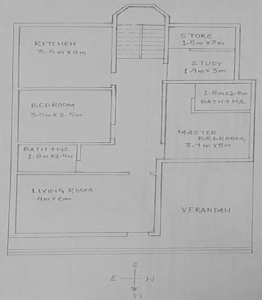
Plate No. 1: Architectural Plan for Ground Floor
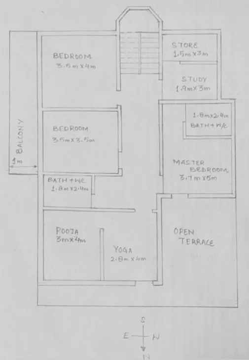
Plate No. 2: Architectural Plan for First Floor
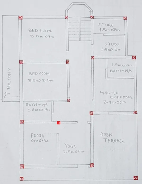
Plate No. 3: Architectural Plan for First Floor showing column position
Details of drawings which must be provided to the site:
- Architectural drawing:
- This drawing includes architectural plan of the structure.
- Plan will include the details of each and every floor.
- It shows the size of all the rooms, walls, doors, windows etc.
- Position of lift, staircase is also given the architectural plan.
- Structural Drawing:
- Centreline plan:
- Centreline plan is given to the site. It shows the centrelines these are used to mark the position of columns.
- Size of column is specified in the centreline plan drawing.
- At the position of columns, the soil is excavated for the construction of footing.
- In the notes section, grade of concrete to be used for different members must be specified.
- Number of days must be specified after which the shuttering can be removed.
- Curing time for different members is also specified.
- Clint details, architect’s details, revision number etc. must be given.
- Drawing title must be provided.
- Grid to grid dimensions is provided in the drawing.
- Layout of Footing:
- Same position of column which is given in the centreline drawing are followed in this layout drawing of footing.
- Position and size of footing is specified in this drawing.
- Based on the size given in the drawing, the marking is done on the ground and with reference to that the excavation is done.
- Thickness of shear wall around the lift or anywhere in the building is given in the same drawing with footing details for the same.
- Footing and column reinforcement details:
- Reinforcement of footing is provided in this drawing.
- Typical reinforcement drawings are provided for footing and columns.
- Thickness of P.C.C. and extension beyond and below footing must be specified with mix details.
- Cross sectional details are provided for the structural members such as footing and columns.
- For footing reinforcement, diameter of bar with number or spacing must be specified in the drawing.
- Details of reinforcement and cross section of footing etc are tabulated in the same drawing sheet with reference to footing number given in the footing layout drawing.
- For any column, details of main reinforcement are specified with number, diameter of bars and position of bars.
- Details of lateral ties with pitch needs to be specified in the column reinforcement drawing needs to be specified.
- All the details related to size of column, reinforcement details (main and tie reinforcement) are tabulated in the same drawing showing all the details with reference to column number given in centreline plan drawing and footing layout drawing.
- Lift Pit Drawing:
- Details of lift pit size below the ground where it is normally provided are specified in detail.
- Material i.e., grade of concrete (R.C.C. and P.C.C.) are specified with thickness of their layers.
- Thickness of sand filling to be provided are also specified in the drawing.
- Waterproofing is done for this pit area which must be specified in the drawing by highlighting the surface which must be provided with water proofing layer.
- In the wall, lintel beam must be provided above the door of the lift. For the lintel beams, vendor must be contacted and the position should be finalized.
- The beam and its details must be given for the position below the slab level.
- Reinforcement details are shown for different section with all the details of diameter of bar, spacing between the bars are shown in the drawings.
- Plinth beam Drawing:
- Columns are shown in the drawing which are connected with the plinth beams.
- Grid to grid dimensions is given as reference in this drawing for the better understanding.
- Cross-sectional size of the beam is specified in the plan.
- Plinth beam numbers are specified in the drawing.
- Cross sectional diagrams of the plinth beams are shown showing details of main reinforcement (top, bottom and side face reinforcement) and stirrups details with number of bars, diameter of bar, spacing between the stirrups are provided.
- With reference to the number of plinth-beam all the details of size, reinforcement is tabulated in the drawing.
- Details related to cranked bar are also specified in the drawing.
- For the plinth beams having same size and reinforcement, details can be given in one cross-section with all the beams number as its reference.
- Size of hooks must be specified for the reinforcement.
- Grades of material must also be specified in note section.
- Slab Drawing:
- Sunken slab must be marked in the drawing.
- Thickness of the sunken slab must be specified in the plan.
- Plan should match with the plan of beams, above which the slab has to be provided.
- Slab thickness must be specified in the drawing.
- Generally, slab beam detailing and slab reinforcement detailing are given in one drawing.
- If the slab is sunken then details of cross-section with its effect on beam must be shown in the drawing.
- In the slab detailing, diameter of bar and spacing between the bars is given with the help of cross section.
- Details of bent-up bars are clearly shown in the plan so that one can bent the bar from required position and proper length is provided in the compression zone.
- Grid to grid dimension may or may not be provided.
- These drawings are provided for all the floors.
- Details of reinforcement of all the structural members must be given for all the floor levels.
- Details of reinforcement for headroom must also be specified.
- Electrical drawing:
- It shows the details of all the electrical fitting.
- It shows the location from where electric wires will be drawn in the building.
Load calculations:
- Dead Load:
- Thickness of slab is 125mm
- D.L. of slab = 0.125 * 25 = 3.125kN/m2
- Size of beam = 230mm X 350mm
- D.L. of each beam (for /m span) = 0.23 * 0.35 * 25 = 2.0125 kN/m
- Size of column = 300 mm X 300 mm
- Height of column = 3.0m (beam depth not included)
- D.L. of each the columns = 0.3 * 0.3 * 3.0 *25 = 6.75 kN
- Thickness of exterior wall = 230mm
- Thickness of interior wall = 150mm
- Number of exterior walls = 12
- Number of interior walls = 13 (on first floor)
- Number of interior walls = 12 (on first floor)
- Height of wall = 3.0m
- Dead load of exterior brick wall = 0.23 * 20 = 6kN/m
- Dead load of interior brick wall = 0.15 * 20 = 3 kN/m
- LIVE LOAD:
Live load has been taken from IS 875 Part-2 for residential building:
- L.L. for Kitchen = 2 kN/m2
- L.L. for Bedroom = 2 kN/m2
- L.L. for Living Room = 2 kN/m2
- L.L. for Bathroom = 2 kN/m2
- L.L. for Store = 3 kN/m2
- L.L. for terrace, Verandah & Balcony = 3 kN/m2
Load combinations that can be considered for the structural design are:
- 1.5 * (D.L. + L.L.)
In case the building is located in a seismic zone then earthquake load must be considered. The combination in that case are given below:
- 1.5 * D.L.`±` 1.5 * E.L.X
- 0.9 * D.L.`±` 1.5 * E.L.X
- 1.2 * D.L. + 1.2 * L.L.`±` 1.2 * E.L.X
- 1.5 * D.L. `±`1.5 * E.L.Z
- 0.9 * D.L. `±`1.5 * E.L.Z
- 1.2 * D.L. + 1.2 * L.L. `±`1.2 * E.L.Z