Creation of geometries by Coordinate system methods using AutoCad
CHALLENGE-1
PREPARED BY- MEGHA GUPTA
Create the geometries from P1 to P2 using all the coordinates system methods. Use the line tool to create the geometries. Where required, use the circle tool.
Aim: Aim of the challenge is to understand the basics of AutoCAD. To learn the basic tools used for drafting purpose.
Introduction: In this project various geometries have been created using various coordinate systems. Following coordinates systems have been used for drawing various geometries:
- cartesian coordinates system
- Absolute coordinate system
- Relative rectangular coordinate system
- Polar coordinate system
As per requirement of the challenge, P1 and P2 geometries have been created using all the coordinate systems whereas the remaining geometries have been creating any one the coordinate systems. Procedure followed for creating the geometries have been given in detail for every drawing.
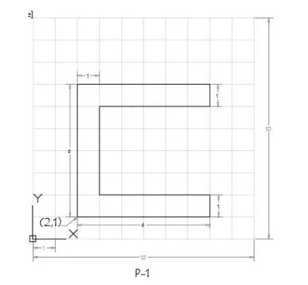
Fig. 1: P1
- Procedure followed for creating P1 geometry:
- Using Cartesian coordinate system:
- Select line command from the tool bar.
- Specify the first point cartesian coordinates as (2,1).
- Specify the next coordinate as (8,1).
- Specify the coordinates for next point as (8,2).
- Specify the coordinates for next point as (3,2).
- Specify the coordinates for next point as (3,6).
- Specify the coordinates for next point as (8,6).
- Specify the coordinates for next point as (8,7).
- Specify the coordinates for next point as (2,7).
- Specify the coordinates for next point as (2,1) or write “c” to close the drawing by joining last point with the first point.
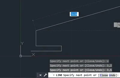
Fig. 2: Drafting of P1 using cartesian coordinate system

Fig. 3: Complete drawing of P1 using cartesian coordinate system
- Using Absolute coordinate system:
- Select line command from the tool bar.
- Specify the first point cartesian coordinates as (2,1).
- Specify the next coordinate as (8,1).
- Specify the coordinates for next point as (8,2).
- Specify the coordinates for next point as (3,2).
- Specify the coordinates for next point as (3,6).
- Specify the coordinates for next point as (8,6).
- Specify the coordinates for next point as (8,7).
- Specify the coordinates for next point as (2,7).
- Specify the coordinates for next point as (2,1) or write “c” to close the drawing by joining last point with the first point.

-
Fig. 4: Complete drawing of P1 using absolute coordinate system
- Using Relative rectangular coordinate system:
- Select line command from the tool bar.
- Specify the first point cartesian coordinates as (2,1).
- Specify the next coordinate as @8,0.
- Specify the coordinates for next point as @0,1.
- Specify the coordinates for next point as @-5,0.
- Specify the coordinates for next point as @0,4.
- Specify the coordinates for next point as @5,0.
- Specify the coordinates for next point as @0,1.
- Specify the coordinates for next point as @-6,0.
- Specify the coordinates for next point as @0,-6 or write “c” to close the drawing by joining last point with the first point.
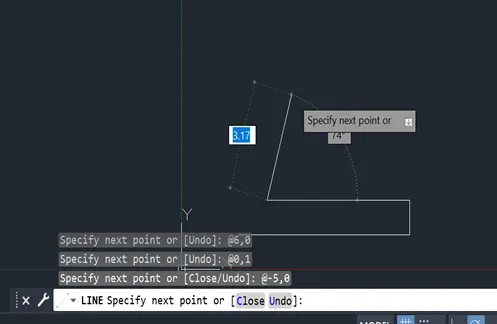
Fig. 5: Drafting of P1 using Relative rectangular coordinate system
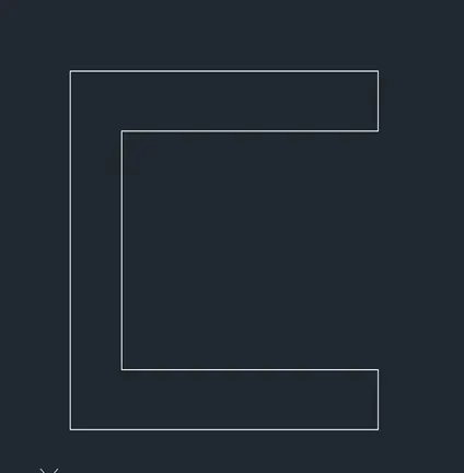
Fig. 6: Complete drawing of P1 using Relative rectangular coordinate system
- Using Polar coordinate system:
- Select line command from the tool bar.
- Specify the first point cartesian coordinates as (2,1).
- Specify the next coordinate as @6<0.
- Specify the coordinates for next point as @1<90.
- Specify the coordinates for next point as @5<180.
- Specify the coordinates for next point as @4<90.
- Specify the coordinates for next point as @5<0
- Specify the coordinates for next point as @1<90.
- Specify the coordinates for next point as @6<180.
- Specify the coordinates for next point as @6<270 or write “c” to close the drawing by joining last point with the first point.
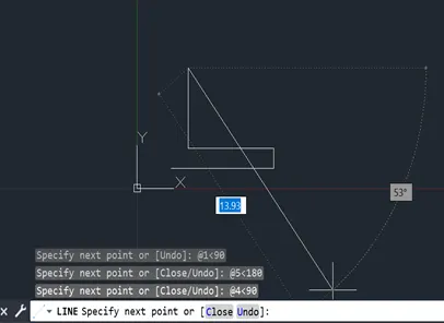
Fig. 7: Drafting of P1 using Polar coordinate system
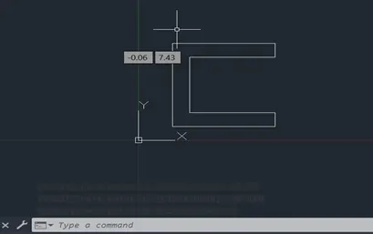
Fig. 8: Complete drawing of P1 using Polar coordinate system
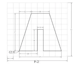
- Fig. 9: P2
-
- Procedure followed for creating P2 geometry:
- Using Cartesian coordinate system:
- Select line command from the tool bar.
- Specify the first point cartesian coordinates as (2,1).
- Specify the next coordinate as (5,1).
- Specify the coordinates for next point as (5,5).
- Specify the coordinates for next point as (6,5).
- Specify the coordinates for next point as (6,1).
- Specify the coordinates for next point as (9,1).
- Specify the coordinates for next point as (7,8).
- Specify the coordinates for next point as (4,8).
- Specify the coordinates for next point as (2,1) or write “c” to close the drawing by joining last point with the first point.
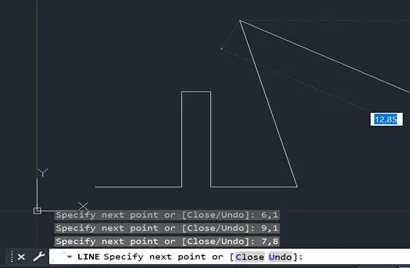
-
Fig. 10: Drafting of P2 using cartesian coordinate system
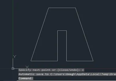
Fig. 11: Complete drawing of P2 using cartesian coordinate system
- Using Absolute coordinate system:
- Select line command from the tool bar.
- Specify the first point cartesian coordinates as (2,1).
- Specify the next coordinate as (5,1).
- Specify the coordinates for next point as (5,5).
- Specify the coordinates for next point as (6,5).
- Specify the coordinates for next point as (6,1).
- Specify the coordinates for next point as (9,1).
- Specify the coordinates for next point as (7,8).
- Specify the coordinates for next point as (4,8).
- Specify the coordinates for next point as (2,1) or write “c” to close the drawing by joining last point with the first point.
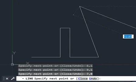
Fig. 12: Drafting of P2 using Absolute coordinate system
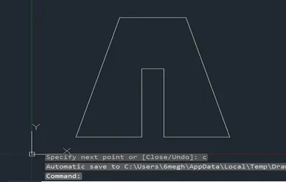
Fig. 13: Complete drawing of P2 using Absolute coordinate system
- Using Relative rectangular coordinate system:
- Select line command from the tool bar.
- Specify the first point cartesian coordinates as (2,1).
- Specify the next coordinate as @3,0.
- Specify the coordinates for next point as @0,4.
- Specify the coordinates for next point as @1,0.
- Specify the coordinates for next point as @0,-4.
- Specify the coordinates for next point as @3,0.
- Specify the coordinates for next point as @-2,7.
- Specify the coordinates for next point as @-3,0.
- Specify the coordinates for next point as @-2,-7 or write “c” to close the drawing by joining last point with the first point.
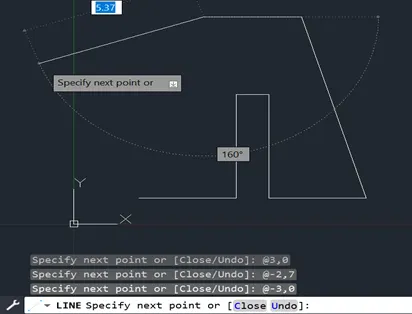
Fig. 14: Drafting of P2 using Relative rectangular coordinate system
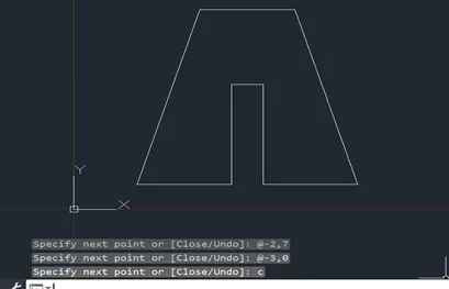
Fig. 15: Complete drawing of P2 using Relative rectangular coordinate system
- Using Polar coordinate system:
- Select line command from the tool bar.
- Specify the first point cartesian coordinates as (2,1).
- Specify the next coordinate as @3<0.
- Specify the coordinates for next point as @4<90.
- Specify the coordinates for next point as @1<0.
- Specify the coordinates for next point as @4<270.
- Specify the coordinates for next point as @3<0
- Specify the coordinates for next point as @7.28<105.946.
- Specify the coordinates for next point as @3<180.
- Specify the coordinates for next point as @7.28< 054 or write “c” to close the drawing by joining last point with the first point.
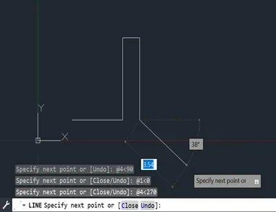
Fig. 16: Drafting of P2 using Polar coordinate system
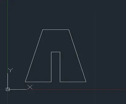
Fig. 17: Complete drawing of P2 using Polar coordinate system
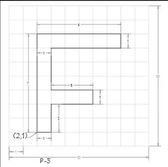
Fig. 18: P3
- Procedure followed for creating P3 geometry:
- Select line command from the tool bar.
- Specify the first point cartesian coordinates as (2,1).
- Specify the next coordinate as @1,0.
- Specify the coordinates for next point as @0,2.
- Specify the coordinates for next point as @3,0.
- Specify the coordinates for next point as @0,1.
- Specify the coordinates for next point as @-3,0.
- Specify the coordinates for next point as @0,3.
- Specify the coordinates for next point as @5,0.
- Specify the coordinates for next point as @0,1.
- Specify the coordinates for next point as @-6,0.
- Specify the coordinates for next point as @0,-7 or write “c” to close the drawing by joining last point with the first point.
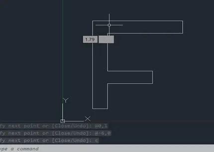
Fig. 19: Complete drawing of P3 using Relative rectangular coordinate system
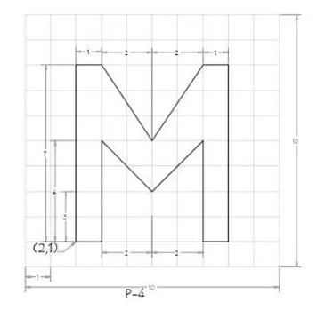
Fig. 20: P4
- Procedure followed for creating P4 geometry:
- Select line command from the tool bar.
- Specify the first point cartesian coordinates as (2,1).
- Specify the next coordinate as @1,0.
- Specify the coordinates for next point as @0,4.
- Specify the coordinates for next point as @2,-2.
- Specify the coordinates for next point as @2,2.
- Specify the coordinates for next point as @0,-4.
- Specify the coordinates for next point as @1,0.
- Specify the coordinates for next point as @0,7.
- Specify the coordinates for next point as @-1,0.
- Specify the coordinates for next point as @-2,-2.
- Specify the coordinates for next point as @-2,2.
- Specify the coordinates for next point as @-1,0.
- Specify the coordinates for next point as @0,-7 or write “c” to close the drawing by joining last point with the first point.
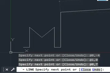
Fig. 21: Drafting of P4 using Relative rectangular coordinate system

Fig. 22: Complete drawing of P4 using Relative rectangular coordinate system
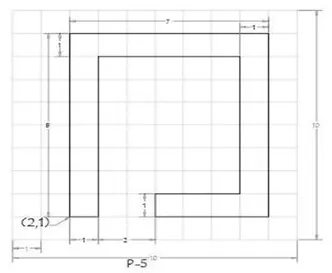
Fig. 23: P5
- Procedure followed for creating P5 geometry:
- Select line command from the tool bar.
- Specify the first point cartesian coordinates as (2,1).
- Specify the next coordinate as @1,0.
- Specify the coordinates for next point as @0,7.
- Specify the coordinates for next point as @5,0.
- Specify the coordinates for next point as @0,-6.
- Specify the coordinates for next point as @-3,0.
- Specify the coordinates for next point as @0,-1.
- Specify the coordinates for next point as @4,0.
- Specify the coordinates for next point as @0,8.
- Specify the coordinates for next point as @-7,0.
- Specify the coordinates for next point as @0,-8 or write “c” to close the drawing by joining last point with the first point.
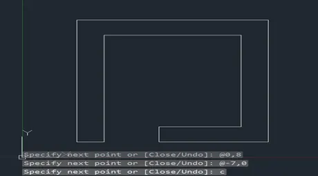
Fig. 24: Complete drawing of P5 on AutoCAD
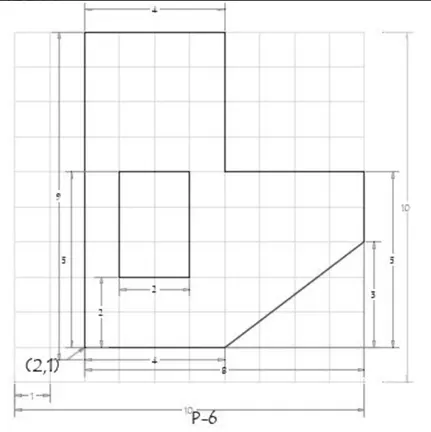
Fig. 25: P6
- Procedure followed for creating P6 geometry:
- Select line command from the tool bar.
- Specify the first point cartesian coordinates as (2,1).
- Specify the next coordinate as @4,0.
- Specify the coordinates for next point as @4,3.
- Specify the coordinates for next point as @0,2.
- Specify the coordinates for next point as @-4,0.
- Specify the coordinates for next point as @0,4.
- Specify the coordinates for next point as @-4,0.
- Specify the coordinates for next point as @0,-9 or write “c” to close the drawing by joining last point with the first point.
- Select rectangle command from toolbar.
- Specify the first corner point as (3,3).
- Write “d” in the command box, so as to specify dimensions for the rectangle.
- Now AutoCAD will ask for length and width. Specify 2 against length and press enter.
- Specify 3 against width and then press enter.
- Now use cursor to specify the side on which the rectangle is required against first corner point. With mouse being located above the corner first point, click left on the mouse.
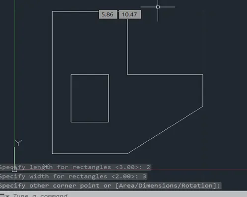
Fig. 26: Complete drawing of P6 on AutoCAD
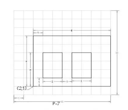
Fig. 27: P7
- Procedure followed for creating P7 geometry:
- Select rectangle command from toolbar.
- Specify the first corner point as (2,1).
- Write “d” in the command box, so as to specify dimensions for the rectangle.
- Now AutoCAD will ask for length and width. Specify 8 against length and press enter.
- Specify 6 against width and then press enter.
- Now use cursor to specify the side on which the rectangle is required against first corner point. With mouse being located above the corner first point, click left on the mouse.
- Again, select rectangle command from toolbar.
- Specify the first corner point as (3,2).
- Write “d” in the command box, so as to specify dimensions for the rectangle.
- Now AutoCAD will ask for length and width. Specify 2 against length and press enter.
- Specify 3 against width and then press enter.
- Now use cursor to specify the side on which the rectangle is required against first corner point. With mouse being located above the corner first point, click left on the mouse.
- Select rectangle command from toolbar again.
- Specify the first corner point as (6,2).
- Write “d” in the command box, so as to specify dimensions for the rectangle.
- Now AutoCAD will ask for length and width. Specify 2 against length and press enter.
- Specify 3 against width and then press enter.
- Now use cursor to specify the side on which the rectangle is required against first corner point. With mouse being located above the corner first point, click left on the mouse.
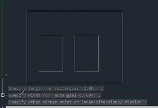
Fig. 28: Complete drawing of P7 on AutoCAD
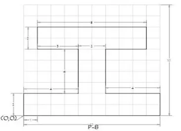
Fig. 29: P8
- Procedure followed for creating P8 geometry:
- Select line command from the tool bar.
- Specify the first point cartesian coordinates as (0,0).
- Specify the next coordinate as @10,0.
- Specify the coordinates for next point as @2,0.
- Specify the coordinates for next point as @-4,0.
- Specify the coordinates for next point as @0,4.
- Specify the coordinates for next point as @3,0.
- Specify the coordinates for next point as @0,2.
- Specify the coordinates for next point as @-8,0.
- Specify the coordinates for next point as @0,-2.
- Specify the coordinates for next point as @3,0.
- Specify the coordinates for next point as @0,-4.
- Specify the coordinates for next point as @-4,0.
- Specify the coordinates for next point as @0,-2 or write “c” to close the drawing by joining last point with the first point.
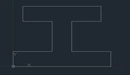
Fig. 30: Complete drawing of P8 on AutoCAD
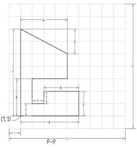
Fig. 31: P9
- Procedure followed for creating P9 geometry:
- Select line command from the tool bar.
- Specify the first point cartesian coordinates as (1,1).
- Specify the next coordinate as @5,0.
- Specify the coordinates for next point as @0,2.
- Specify the coordinates for next point as @-3,0.
- Specify the coordinates for next point as @0,-1.
- Specify the coordinates for next point as @1,0.
- Specify the coordinates for next point as @0,2.
- Specify the coordinates for next point as @3,0.
- Specify the coordinates for next point as @0,2.
- Specify the coordinates for next point as @-4,2.
- Specify the coordinates for next point as @0,-7 or write “c” to close the drawing by joining last point with the first point.
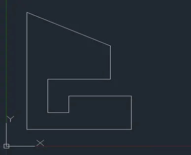
Fig. 32: Complete drawing of P9 on AutoCAD
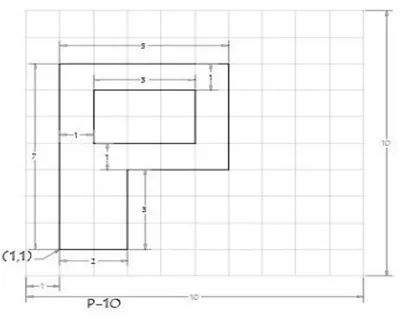
Fig. 33: P10
- Procedure followed for creating P10 geometry:
- Select line command from the tool bar.
- Specify the first point cartesian coordinates as (1,1).
- Specify the next coordinate as @2,0.
- Specify the coordinates for next point as @0,3.
- Specify the coordinates for next point as @3,0.
- Specify the coordinates for next point as @0,4.
- Specify the coordinates for next point as @-5,0.
- Specify the coordinates for next point as @0,-7 or write “c” to close the drawing by joining last point with the first point.
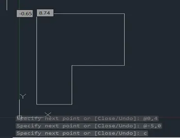
Fig. 34: Complete drawing of exterior part of P10 on AutoCAD
- Select rectangle command from toolbar again.
- Specify the first corner point as (2,5).
- Write “d” in the command box, so as to specify dimensions for the rectangle.
- Now AutoCAD will ask for length and width. Specify 3 against length and press enter.
- Specify 2 against width and then press enter.
- Now use cursor to specify the side on which the rectangle is required against first corner point. With mouse being located above the corner first point, click left on the mouse.
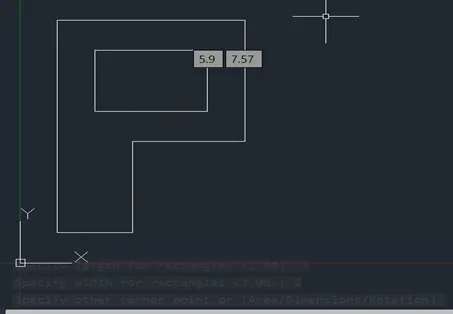
Fig. 35: Complete drawing of P10 on AutoCAD
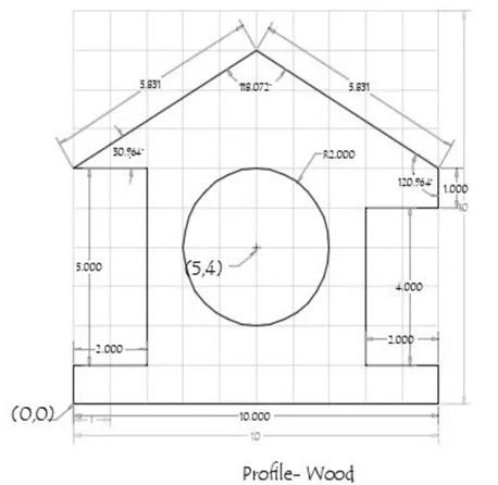
Fig. 36: Profile – wood
- Procedure followed for creating Profile-wood geometry:
- Select line command from the tool bar.
- Specify the first point cartesian coordinates as (0,0).
- Specify the next coordinate as (10,0).
- Specify the coordinates for next point as (10,1).
- Specify the coordinates for next point as (8,1).
- Specify the coordinates for next point as (8,5).
- Specify the coordinates for next point as (10,5).
- Specify the coordinates for next point as (10,6).
- Specify the coordinates for next point as (5,9).
- Specify the coordinates for next point as (0,6).
- Specify the coordinates for next point as (2,6).
- Specify the coordinates for next point as (2,1).
- Specify the coordinates for next point as (0,1).
- Specify the coordinates for next point as (0,0) or write “c” to close the drawing by joining last point with the first point.
- Select circle from toolbar.
- Specify the centre of circle as (5,4).
- Then AutoCAD will ask about the radius. Write 2 and press enter.
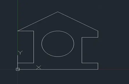
Fig. 37: Complete drawing of Profile-wood on AutoCAD
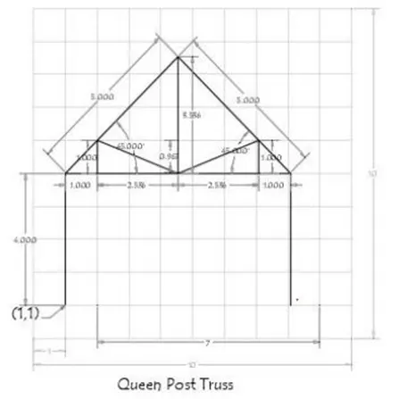
Fig. 38: Queen Post Truss
- Procedure followed for creating Queen post truss geometry:
- Select line command from the tool bar.
- Specify the first point cartesian coordinates as (1,1).
- Specify the next coordinate as @0,4.
- Specify the coordinates for next point as @5<45.
- Specify the coordinates for next point as @5<315.
- Specify the coordinates for next point as @4<90.
- Press ESC on keyboard.
- Select line command from toolbar.
- Click on the point having cartesian coordinates (7, 5).
- Now specify the position of next point as @1<180.
- Specify the position of next point as @1<90.
- Specify the coordinates for next point as @-2.536,-1.
- Specify the coordinates for next point as @2.536,0.
- Press ESC on keyboard.
- Select line command from toolbar.
- Click on the point having cartesian coordinates (4.536, 5).
- Now specify the position of next point as @3.536<90.
- Press ESC on keyboard.
- Select line command from toolbar.
- Click on the point having cartesian coordinates (4.536, 5).
- Specify the coordinates for next point as @-2.536,1.
- Specify the coordinates for next point as @1<270.
- Specify the coordinates for next point as @-2.536,-1.
- Specify the coordinates for next point as @2.536<0.
- Press ESC on keyboard.
- Select line command from toolbar.
- Click on the point having cartesian coordinates (2, 5).
- Specify the coordinates for next point as @1<180.
- Press ESC on keyboard.
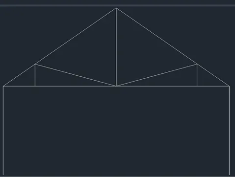
Fig. 39: Complete drawing of Queen post truss on AutoCAD
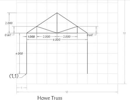
Fig. 40: Howe Truss
- Procedure followed for creating Howe post truss geometry:
- Select line command from the tool bar.
- Specify the first point cartesian coordinates as (1,1).
- Specify the next coordinate as @4<90.
- Specify the coordinates for next point as @1<0.
- Specify the coordinates for next point as @2<0.
- Specify the coordinates for next point as @2<0.
- Specify the position of next point as @1<0.
- Press ESC on keyboard.
- Select line command from toolbar.
- Click on the point having cartesian coordinates (1, 5).
- Now specify the position of next point as @3,2.
- Specify the position of next point as @3,-2.
- Press ESC on keyboard.
- Select line command from toolbar.
- Click on the point having cartesian coordinates (4, 7).
- Specify the position of next point as @2<270.
- Specify the position of next point as @2,0.667.
- Specify the position of next point as @0.667<270.
- Press ESC on keyboard.
- Select line command from toolbar.
- Click on the point having cartesian coordinates (4, 5).
- Specify the position of next point as @-2,0.667.
- Specify the position of next point as @0.667<270.
- Press ESC on keyboard.
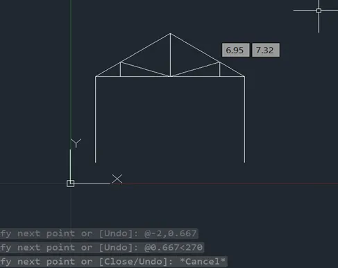
Fig. 41: Complete drawing of Howe post truss on AutoCAD
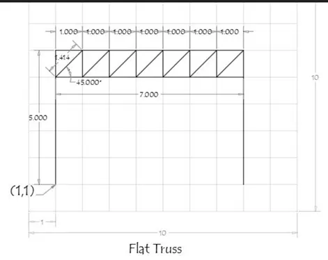
Fig. 42: Flat Truss
- Procedure followed for creating Flat truss geometry:
- Select line command from the tool bar.
- Specify the first point cartesian coordinates as (1,1).
- Specify the next coordinate as @5<90.
- Specify the coordinates for next point as @7<0.
- Specify the coordinates for next point as @5<270.
- Press ESC on keyboard.
- Select line command from toolbar.
- Click on the point having cartesian coordinates (1, 5).
- Now specify the position of next point as @7<0.
- Press ESC on keyboard.
- Select line command from toolbar.
- Click on the point having cartesian coordinates (1, 5).
- Now specify the position of next point as @1.414<45.
- Specify the position of next point as @1<270.
- Now specify the position of next point as @1.414<45.
- Specify the position of next point as @1<270.
- Now specify the position of next point as @1.414<45.
- Specify the position of next point as @1<270.
- Now specify the position of next point as @1.414<45.
- Specify the position of next point as @1<270.
- Now specify the position of next point as @1.414<45.
- Specify the position of next point as @1<270.
- Now specify the position of next point as @1.414<45.
- Specify the position of next point as @1<270.
- Now specify the position of next point as @1.414<45.
- Press ESC on keyboard.
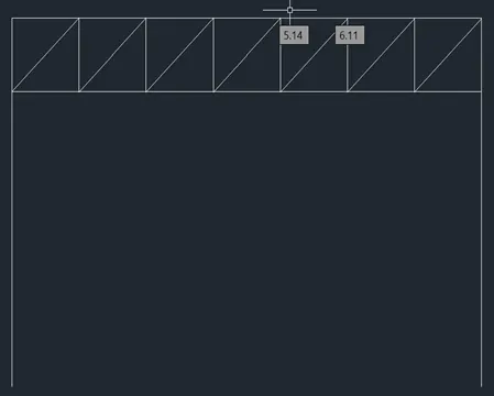
Fig. 43: Complete drawing of Flat truss on AutoCAD
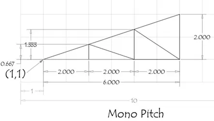
Fig. 44: Mono Pitch Truss
- Procedure followed for creating Mono Pitch Truss geometry:
- Select line command from the tool bar.
- Specify the first point cartesian coordinates as (1,1).
- Specify the next coordinate as @2<0.
- Specify the coordinates for next point as @2<0.
- Specify the coordinates for next point as @2<0.
- Specify the position of next point as @2<90.
- Specify the position of next point as (1,1).
- Press ESC on keyboard.
- Select line command from toolbar.
- Click on the point having cartesian coordinates (3,1).
- Now specify the position of next point as @0.667<90.
- specify the position of next point as @2,-0.667.
- Now specify the position of next point as @1.333<90.
- specify the position of next point as @2,-1.333.
- Press ESC on keyboard.
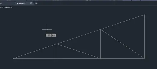
Fig. 45: Complete drawing of Mono pitch truss on AutoCAD