Creating a Floor plan, Footing detail and Isometric view using AutoCad
CHALLENGE-2
PREPARED BY- MEGHA GUPTA
Create a floor plan, footing detail and isometric view using AutoCAD.
Aim: Aim of the challenge is to understand the basics tools used for the purpose of drafting in AutoCAD.
Introduction: In this project various geometries have been created using various tools like rectangle, polyline, move, offset etc. available in AutoCAD.
As per requirement of the challenge, various drawings showing footing details, floor plan and isometric view of staircase and wall have been created. Metric system has been used for the drafting in this project. Procedure followed for creating the drawing has been discussed below with each of the drawing.
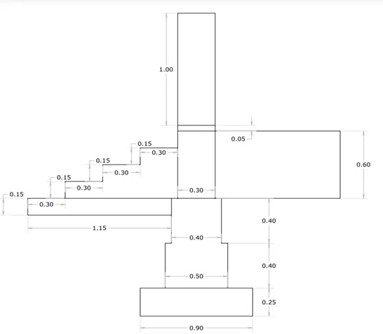
Fig. 1: C1
Procedure followed for drawing C1:
- Select rectangle command from the toolbar.
- Select a base point to draw the rectangle.
- Write “d” in the command box and press “enter”. Now specify 0.9 against length and press enter.
- Specify 0.25 against width and press enter.
- According to required position of rectangle, locate the cursor and press left button on mouse.
- Select Line command from the toolbar.
- Select a first point at 0.2m from left end of the top of the base to draw the line.
- Now keeping vertically upward direction of the line (making sure that ortho is on) write 0.4 and press enter.
- Now change the direction of line to horizontal (towards right) and write 0.05 and press enter.
- Now extend the line in vertically upward direction and enter the length as 0.4 and press enter.
- Now change the direction of line to horizontal (towards right) and write 0.05 and press entre.
- Now extend the line in vertically upward direction and enter the length as 1.65 and press enter.
- Now change the direction of line to horizontal (towards right) and write 0.3 and press entre.
- Now keeping vertically downward direction of the line (making sure that ortho is on) write 1.65 and press enter.
- Now change the direction of line to horizontal (towards right) and write 0.05 and press entre.
- Now extend the line in vertically downward direction and enter the length as 0.4 and press enter.
- Now change the direction of line to horizontal (towards right) and write 0.05 and press entre.
- Now extend the line in vertically downward direction and enter the length as 0.4 and press enter. Then press “ESC”.
- Select Offset command from Modify toolbar. Specify offset as 1 and press enter. Now select the line with 0.3m length at the top of the wall. Move cursor below it and press left button on mouse. Press “ESC”.
- Now, again select Offset command from Modify toolbar. Specify offset as 0.05 and press enter. Now select the line (last drawn) with 0.3m. Move cursor below it and press left button on mouse. Press “ESC”.
- Select Line command from the toolbar.
- Select a first point at the right end of the top step of the footing to draw the line.
- Now keeping horizontally right direction of the line (making sure that ortho is on) write 1(assumed, as not given in the question) and press enter.
- Now change the direction of line to vertically upward direction and write 0.6 and press enter.
- Now change the direction of line to horizontal (towards left) and write 1 and press entre. Press “ESC”.
- Select line command from the toolbar.
- This time select the left top end of the footing as first point for drawing the line.
- Now keeping horizontally left direction of the line (making sure that ortho is on) write 1.15 and press enter.
- Now change the direction of line to vertically downward direction and write 0.15 and press enter.
- Now keeping horizontally right direction of the line write 1.15 and press enter. Press “enter”.
- Select line command. Draw a line in vertically upward direction from the extreme left point of the recently drawn section. Enter the length of line as 0.15 and press “enter”. Press “ESC”.
- Select Move command from the toolbar and move the last drawn line by 0.3m in horizontal direction. Then press “enter”.
- Now, again select line command from the toolbar
- Keeping direction of the line as horizontal (towards right) specify length of of the line as 0.3. Press Enter.
- Now change the direction of line to vertically upward direction and write 0.15 and press enter.
- Now keeping horizontally right direction of the line write 0.3 and press enter. Press “enter”.
- Now change the direction of line to vertically upward direction and write 0.15 and press enter.
- Now keeping horizontally right direction of the line write 0.3 and press enter. Press “enter”. Press “ESC”.
- To specify dimensions on the drawing, select linear command from annotation toolbar. Click on the start point and end point of the line for which dimension is required to be specified.
- Repeat the same process for every line so as to show the dimensions.
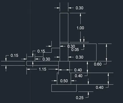
Fig. 2: C.S. of load bearing wall over spread footing
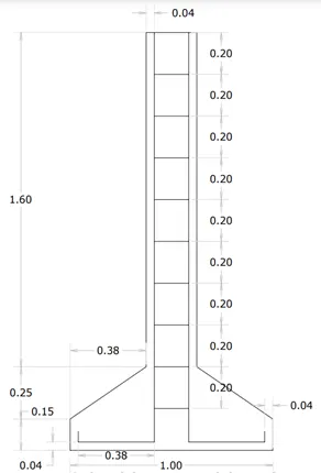
Fig. 3: C2
Procedure followed for drawing C2:
- Select Line command from the toolbar.
- Select a first point to draw the line.
- Now change the direction of line to horizontal (towards right) and write 1 and press entre.
- Now keeping vertically upward direction of the line (making sure that ortho is on) write 0.15 and press enter.
- Now change the direction of line to horizontal (towards left) and write 1 and press entre.
- Now extend the line in vertically downward direction and enter the length as 0.15 and press enter.
- Select line command and keeping vertically upward direction for the line enter the dimension as 0.25 and press enter.
- Now change the direction of line to horizontal (towards right) and write 0.24 and press enter.
- Now extend the line in vertically downward direction and enter the length as 0.25 and press enter.
- Now select this recent drawn box and select move command from the toolbar.
- Selecting the bottom left point as base point then specify the displacement in horizontal direction as 0.38 and press “enter”.
- Now select the line command from the toolbar and click on the top left end bottom box and connect it with top left end of the top box. Now press “ESC”.
- Again, select line command from toolbar. Now click on the top right end of the bottom box and connect it with the top right of the top box. Then press “ESC”.
- Now select the vertical and top horizontal part of upper box and upper horizontal side of bottom box and press “delete”.
- Select line command from the toolbar. Select top left point of the drawing as first point of line.
- Now extend the line in vertically upward direction and enter the length as 1.6 and press enter.
- Now change the direction of line to horizontal (towards right) and write 0.24 and press enter.
- Now extend the line in vertically downward direction and enter the length as 1.6 and press enter.
- Now change the direction of line to horizontal (towards right) and write 0.05 and press entre. Press “ESC”.
- Select offset command from the Modify toolbar. Specify offset as 0.04 and press enter.
- Select the left vertical face (column) as reference for offset. Now click on right side of the face so as to get the same line at 0.04m spacing.
- Now select the right vertical face of the column and place cursor on the left side of that face and press left button on the mouse.
- Now select the bottom of the footing and drag mouse above it and then press left button of mouse.
- Now select the vertical left face of the footing and drag cursor to the right side and press left button on the mouse.
- Now select the vertical right face of the footing and drag cursor to the left side and press left button on the mouse.
- Select Extend command from modify toolbar.
- Now click on the vertical reinforcements one by one so as to extend it till the bottom reinforcement.
- Select trim command from the toolbar. Now, click on the central part of the bottom reinforcement line to delete the unwanted portion.
- Similarly remove the extra part of hook and using trim command delete the unwanted portion of the reinforcement.
- Select line command from the toolbar.
- Select the top point of vertical reinforcement as first point and click on the top position of vertical reinforcement as the second point for the line.
- Now, select this recently drawn line. Then select move command from the toolbar.
- Now, select the left end of the line as base point for moving the object in vertically downward direction and specify the displacement as 0.2. Then press “enter”.
- Now select Offset command from the toolbar. Click on the last line that was moved by 0.2m. Now drag the cursor below that line and press left key on the mouse.
- Now select this new line and drag the cursor below it and press left key on the mouse.
- Repeat the same process, until all the required ties have not been obtained.
- To specify dimensions on the drawing, select linear command from annotation toolbar. Click on the start point and end point of the line for which dimension is required to be specified.
- Repeat the same process for every line so as to show the dimensions.
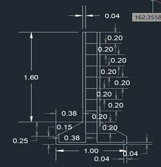
Fig. 4: C.S. Isolated Footing
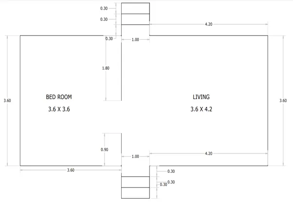
Fig. 5: C3
Procedure followed for drawing C3:
- Select Line command from the toolbar.
- Select a first point to draw the line.
- Now change the direction of line to horizontal (towards left) and write 3.6 and press entre.
- Now keeping vertically upward direction of the line (making sure that ortho is on) write 3.6 and press enter.
- Now change the direction of line to horizontal (towards right) and write 3.6 and press enter.
- Now extend the line in vertically downward direction and enter the length as 3.6 and press enter.
- Select line command and keeping vertically downward direction for the line enter the dimension as 0.9 and press enter.
- Now change the direction of line to horizontal (towards right) and write 1 and press enter.
- Now extend the line in vertically upward direction and enter the length as 0.9 and press enter.
- Now change the direction of line to horizontal (towards right) and write 4.2 and press enter.
- Now keeping vertically upward direction of the line (making sure that ortho is on) write 3.6 and press enter.
- Now change the direction of line to horizontal (towards left) and write 4.2 and press enter.
- Now extend the line in vertically upward direction and enter the length as 0.9 and press enter.
- Now change the direction of line to horizontal (towards left) and write 1 and press enter.
- Now extend the line in vertically downward direction and enter the length as 0.9 and press enter. Then press “ESC”.
- Select Offset command from Modify toolbar. Specify offset as 0.3 and press enter. Now select the line with 1m length at the top showing step. Move cursor below it and press left button on mouse.
- Now, select the new line drawn using offset and drag cursor below it and press left key on the mouse.
- Repeat same process for the other site to draw the stair case.
- Draw a line cutting the intermediate line at 0.9 m from bottom using line command. Copy this line and paste the same line at a distance of 0.9m from its original position. Keep the original line.
- Select trim command from the toolbar and click on the portion where opening is required between those new drawn lines. Press “ESC”.
- Now select those additionally drawn line which are no more required. Then press delete.
- To specify dimensions on the drawing, select linear command from annotation toolbar. Click on the start point and end point of the line for which dimension is required to be specified.
- Repeat the same process for every line so as to show the dimensions.
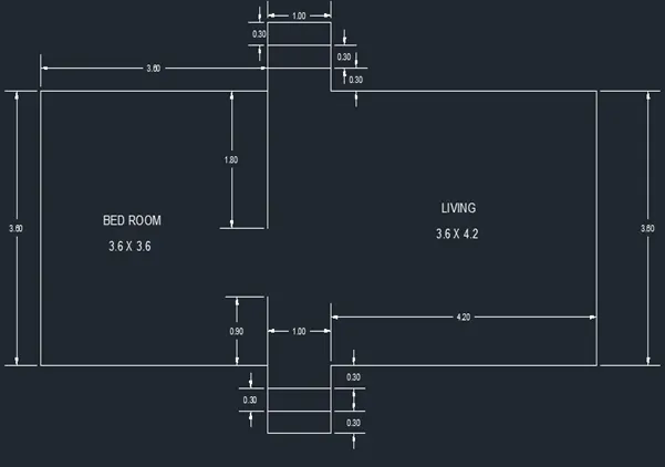
Fig. 6: Line diagram of a two-bedroom building
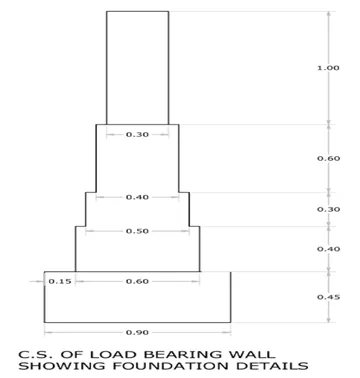
Fig. 7: C4
Procedure followed for drawing C4:
- Select rectangle command from the toolbar.
- Select a base point to draw the rectangle.
- Write “d” in the command box and press “enter”. Now specify 0.9 against length and press enter.
- Specify 0.45 against width and press enter.
- According to required position of rectangle, locate the cursor and press left button on mouse.
- Select line command from toolbar.
- Click at the top left end of the rectangle for selecting the starting point of the line.
- Now keeping vertical direction of the line (making sure that ortho is on) write 0.4 and press enter.
- Now change the direction of line to horizontal (towards right) and write 0.05 and press enter.
- Now extend the line in vertical direction and enter the length as 0.3 and press enter.
- Now change the direction of line to horizontal (towards right) and write 0.05 and press enter.
- Now extend the line in vertical direction and enter the length as 0.6 and press enter.
- Now change the direction of line to horizontal (towards right) and write 0.4 and press enter.
- Now extend the line in vertically downward direction and enter the length as 0.6 and press enter.
- Now change the direction of line to horizontal (towards right) and write 0.05 and press enter.
- Now extend the line in vertically downward direction and enter the length as 0.3 and press enter.
- Now change the direction of line to horizontal (towards right) and write 0.05 and press enter.
- Now extend the line in vertically downward direction and enter the length as 0.4 and press enter. Then press “enter” again.
- Select line command and select top left point of the drawing as first point.
- Extend the line vertically upward and specify the distance as 1 and press enter.
- Now change the direction of line to horizontal (towards right) and write 0.3 and press enter.
- Now extend the line in vertically downward direction and enter the length as 1 and press enter. Then press “enter” again.
- Now select this top part of the wall footing i.e. of 1m height and 0.3m wide.
- Select move command from toolbar.
- Select bottom left point as the base for moving the selection. Now specify the displacement (in horizontal direction) as 0.05 and press “enter”.
- Now select the entire drawing except the base i.e. 0.9m X 0.45m rectangular portion.
- Select move command from the toolbar.
- Select bottom extreme left point of the selected portion and specify the displacement (in horizontal direction) as 0.15 and press “enter”.
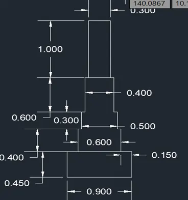
Fig. 8: C.S. Load bearing wall showing foundation details
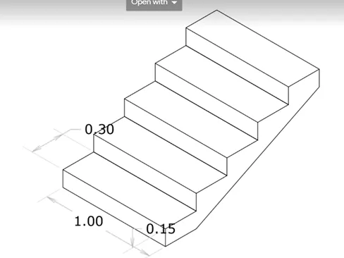
Fig. 9: C5
Procedure followed for drawing C5:
- Go to snap setting and select isometric snap from there. Now isometric diagram can be drawn.
- Keep ortho on and select isoplane right command.
- Select the first point position for the line.
- Now keeping the direction of line to horizontal (towards left i.e. -ve X-direction) and write 0.3 and press enter.
- Now extend the line in vertically upward direction (in Y direction) and enter the length as 0.15 and press enter.
- Now change the direction of line to horizontal (towards right i.e. +ve X-direction) and write 0.3 and press enter.
- Now extend the line in vertically upward direction (in Y direction) and enter the length as 0.15 and press enter.
- Now change the direction of line to horizontal (towards right i.e. +ve X-direction) and write 0.3 and press enter.
- Now extend the line in vertically upward direction (in Y direction) and enter the length as 0.15 and press enter.
- Now change the direction of line to horizontal (towards right i.e. +ve X-direction) and write 0.3 and press enter.
- Now extend the line in vertically upward direction (in Y direction) and enter the length as 0.15 and press enter.
- Now change the direction of line to horizontal (towards right i.e. +ve X-direction) and write 0.3 and press enter.
- Now extend the line in vertically upward direction (in Y direction) and enter the length as 0.15 and press enter.
- Now change the direction of line to horizontal (towards right i.e. +ve X-direction) and write 0.3 and press enter.
- Now extend the line in vertically downward direction (in Y direction) and enter the length as 0.15 and press enter.
- Join this point with the first point of the drawing. Press “ESC”.
- Press F5 so that isoplane left is selected.
- Now, select line command from the toolbar.
- Select bottom corner point as first point for the line and keeping direction of line as Z -ve, specify the length as 1 and press enter.
- Now extend the line in vertically upward direction and enter the length as 0.15 and press enter.
- Now change the direction of line to horizontal (towards right +ve Z) and write 1 and press enter. Press “ESC”.
- Now, select line command from the toolbar.
- Select next corner point (bottom junction of rise and tread) as first point for the line and keeping direction of line as Z -ve, specify the length as 1 and press enter.
- Now extend the line in vertically upward direction and enter the length as 0.15 and press enter.
- Now change the direction of line to horizontal (towards right +ve Z) and write 1 and press enter. Press “ESC”.
- Repeat the same process for each of the step.
- Once, the riser for all the steps have been created again press F5 and select isoplane top.
- Select line command and join top end of riser with the bottom end of next step’s riser in order to create trade. Press “enter”.
- Select line command again. Repeating the same process, draw all the trades.
- To specify dimensions on the drawing, select linear command from annotation toolbar. Click on the start point and end point of the line for which dimension is required to be specified.
- Repeat the same process for every line so as to show the dimensions.
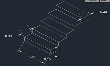
Fig. 10: Isometric view of steps
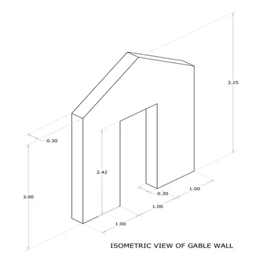
Fig. 11: C6
Procedure followed for drawing C5:
- Go to snap setting and select isometric snap from there. Now isometric diagram can be drawn.
- Keep ortho on and select isoplane right command.
- Select the first point position for the line.
- Now extend the line in vertically downward direction (in -ve Y direction) and enter the length as 3 and press enter.
- Now change the direction of line to horizontal (towards right i.e. +ve X-direction) and write 1 and press enter.
- Now extend the line in vertically upward direction (in Y direction) and enter the length as 2.42 and press enter.
- Now change the direction of line to horizontal (towards right i.e. +ve X-direction) and write 1 and press enter.
- Now extend the line in vertically downward direction (in Y direction) and enter the length as 2.42 and press enter.
- Now change the direction of line to horizontal (towards right i.e. +ve X-direction) and write 1 and press enter.
- Now extend the line in vertically upward direction (in Y direction) and enter the length as 3 and press enter.
- Now change the direction of line to horizontal (towards right i.e. +ve X-direction) and write 0.3 and press enter. Press “ESC”.
- Select line command from the toolbar.
- Select start point as the left corner of the drawing. Keeping the direction of line as horizontal (towards right) enter 1.5 distance then press “enter”.
- Now extend the line in vertically upward direction (in Y direction) and enter the length as 3.25 and press enter. Press “ESC”.
- Join the top end of both the vertical faces with the top end of the recently drawn line one by one.
- Press F5 so that isoplane left is selected.
- Now, select line command from the toolbar.
- Select bottom corner point as first point for the line and keeping direction of line as Z -ve, specify the length as 0.3 and press enter.
- Now extend the line in vertically upward direction and enter the length as 3 and press enter.
- Now change the direction of line to horizontal (towards right +ve Z) and write 0.3 and press enter. Press “ESC”.
- Now, select line command from the toolbar.
- Select inner point of the top of the wall i.e. located at 3.25m from bottom as first point for the line and keeping direction of line as Z -ve, specify the length as 0.3 and press enter.
- Join this end with the last point of previously drawn 0.3m line so as to show the thickness of wall.
- Repeat the same process for another side of the wall. Then press “ESC”.
- To draw the thickness of the wall, select the line command from the toolbar.
- Select the front bottom corner of door as starting point of the wall.
- Now extend the line in -ve Z direction and enter the length as 0.3 and press enter.
- Press F5 and select isoplane top.
- Keeping vertical direction for the line, extend the line by 3m.
- Select Trim command from the toolbar, remove the extra portion which was extended beyond top part of the door.
- Select the line which was drawn to locate the top point of the wall and press delete.
- To specify dimensions on the drawing, select linear command from annotation toolbar. Click on the start point and end point of the line for which dimension is required to be specified.
- Repeat the same process for every line so as to show the dimensions.
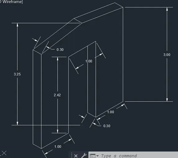
Fig. 12: Isometric view of Gable wall