Drafting of various geometries using Chamfer, Fillet tool in AutoCad
CHALLENGE-3
PREPARED BY- MEGHA GUPTA
Drafting of various elements using AutoCAD.
Aim: Aim of the challenge is to understand the basics tools used for the purpose of drafting in AutoCAD.
Introduction: In this project various geometries have been created using various tools like rectangle, polyline, circle, move, offset etc. available in AutoCAD.
As per requirement of the challenge, various drawings showing different element details have been created. Decimal system, architectural system, engineering system has been used for the drafting in this project. Procedure followed for creating the drawing has been discussed below with each of the drawing.
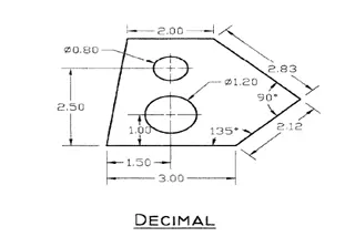
Fig. 1: Drawing 1
Procedure followed for drawing Element of Fig.1:
- Select the current drawing units as decimal.
- Select polyline command from the toolbar.
- Specify the first point for the line.
- Select length and keeping horizontal (towards right) direction of the line (making sure that ortho is on) write 3.0 and press enter.
- Specify in the command box @2.12<45 and Press enter.
- Specify in the command box @2.83<135 and Press enter.
- Specify in the command box @2.0<180 and Press enter.
- Press “c” and enter.
- Select Line command from the toolbar.
- Select the bottom left point of the drawn boundary.
- Keeping the direction as horizontal (towards right) specify the distance as 1.5 and press enter.
- Specify in the command box @1.0<90 and Press enter.
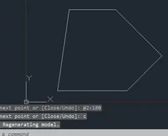
Fig. 2
- Now, select circle command from the toolbar.
- Select top of last drawn line as the centre of circle and press “d” to specify diameter. Then press enter.
- Now, give the value of diameter as 1.2 and press enter.
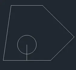
Fig. 3
- Select the extra line drawn for pointing the centre of circle and press “delete”.
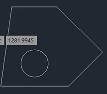
Fig. 4
- Again, select Line command from the toolbar.
- Select the centre of the circle as the first point for the line.
- Keeping line vertical (with ortho on) and specify the distance as 1.5 and press enter.
- Select top of last drawn line as the centre of circle and press “d” to specify diameter. Then press enter.
- Now, give the value of diameter as 0.8 and press enter.
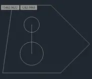
Fig. 5
- Select the extra drawn line and press “delete”.
- To specify dimensions on the drawing, select linear command from annotation toolbar. Click on the start point and end point of the line for which dimension is required to be specified.
- Repeat the same process for every line so as to show the dimensions.
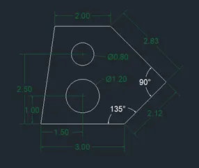
Fig. 6: Complete drawing
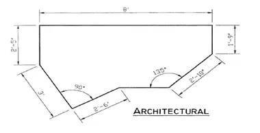
Fig. 7
Procedure followed for drawing Element of Fig. 7:
- Select the current drawing units as architectural.
- Select polyline command from the toolbar.
- Specify the first point for the line.
- Specify in the command box @2’-10”<45 and Press enter.
- Specify in the command box @1’-9”<90 and Press enter.
- Specify in the command box @8’-0”<180 and Press enter.
- Specify in the command box @2’-5”<270 and Press enter.
- Specify in the command box @3’-0”<320.2 and Press enter.
- Specify in the command box @2’-6”<50.2 and Press enter.
- Press “c” and enter.
- To specify dimensions on the drawing, select linear command from annotation toolbar. Click on the start point and end point of the line for which dimension is required to be specified.
- Repeat the same process for every line so as to show the dimensions.
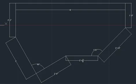
Fig. 8
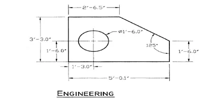
Fig. 9
Procedure followed for drawing Element of Fig. 9:
- Select the current drawing units as engineering.
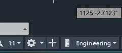
Fig. 10
- Select polyline command from the toolbar.
- Specify the first point for the line.
- Specify in the command box @2’-6.5”<180 and Press enter.
- Specify in the command box @3’-3”<270 and Press enter.
- Specify in the command box @5’-0.1”<0 and Press enter.
- Specify in the command box @1’-6”<90 and Press enter.
- Press “c” and enter.
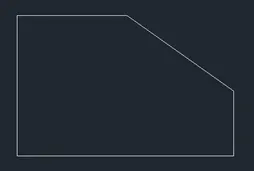
Fig. 11
- Select Line command from the toolbar.
- Select the bottom left point of the drawn boundary.
- Keeping the direction as horizontal (towards right) specify the distance as 1’-3” and press enter.
- Specify in the command box @1’-6”<90 and Press enter.
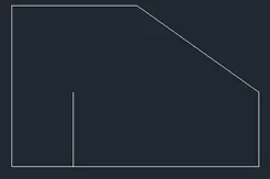
Fig. 12
- Now, select circle command from the toolbar.
- Select top of last drawn line as the centre of circle and press “d” to specify diameter. Then press enter.
- Now, give the value of diameter as 1’-6” and press enter.
- Select the extra drawn line and press “delete”.
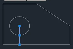
Fig. 13
- To specify dimensions on the drawing, select linear command from annotation toolbar. Click on the start point and end point of the line for which dimension is required to be specified.
- Repeat the same process for every line so as to show the dimensions.
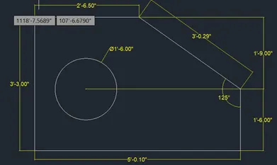
Fig. 14
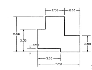
Fig. 15
Procedure followed for drawing Element of Fig. 15:
- Select the current drawing units as decimal.
- Select polyline command from the toolbar.
- Specify the first point for the line.
- Specify in the command box @3<0 and Press enter.
- Specify in the command box @0.5<270 and Press enter.
- Specify in the command box @2.5<0 and Press enter.
- Specify in the command box @2.5<90 and Press enter.
- Specify in the command box @2<180 and Press enter.
- Specify in the command box @3<90 and Press enter.
- Specify in the command box @2.5<180 and Press enter.
- Specify in the command box @2<270 and Press enter.
- Specify in the command box @1<180 and Press enter.
- Press “c” and enter.
- To specify dimensions on the drawing, select linear command from annotation toolbar. Click on the start point and end point of the line for which dimension is required to be specified.
- Repeat the same process for every line so as to show the dimensions.
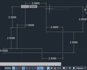
Fig. 16
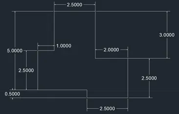
Fig. 17
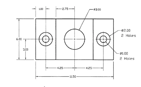
Fig. 18
Procedure followed for drawing Element of Fig. 15:
- Select the current drawing units as decimal.
- Select line command from the toolbar.
- Specify the first point for the line.
- Specify in the length of the line as 6 keeping direction vertically downward (Otho must be on) and Press enter.
- Specify in the length of the line as 6 keeping direction horizontal (towards right) and Press enter.
- Specify in the length of the line as 6 keeping direction vertically upward (Otho must be on) and Press enter.
- Specify in the length of the line as 6 keeping direction horizontal (towards left) and Press enter. Press “ESC”.
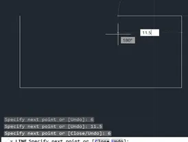
Fig. 19
- Select the offset command and specify the offset as 1.5 and Press enter.
- Now select the left face of the boundary and drag the cursor inner side the box and press left button of the mouse.
- Now select the right face of the boundary and drag the cursor inner side the box and press left button of the mouse.
- Select line command from the toolbar.
- Select the top left corner of the box as start point and specify in the command box @1.5<90 and Press enter.
- Specify in the command box @3<270 and Press enter.
- Specify in the command box @8.5<0 and Press enter. Press “ESC”.
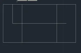
Fig. 20
- Now, select circle command from the toolbar.
- Select bend of last drawn line as the centre of circle and press “d” to specify diameter. Then press enter.
- Now, give the value of diameter as 1 and press enter.
- Again, select circle command from the toolbar.
- Select bend of last drawn line as the centre of circle and press “d” to specify diameter. Then press enter.
- Now, give the value of diameter as 2 and press enter.
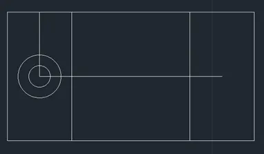
Fig. 21
- Select the circles drawn and then select copy command from the toolbar.
- Now select the centre of circles as the base point for making the copy of circles. Then sel2ct the other end of the line as the point for pasting the circle.
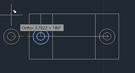
Fig. 22
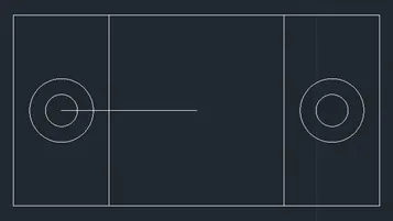
Fig. 23
- Select the unrequired line now and press delete.
- To specify dimensions on the drawing, select linear command from annotation toolbar. Click on the start point and end point of the line for which dimension is required to be specified.
- Repeat the same process for every line so as to show the dimensions.
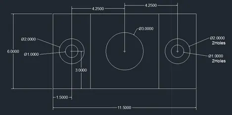
Fig. 24
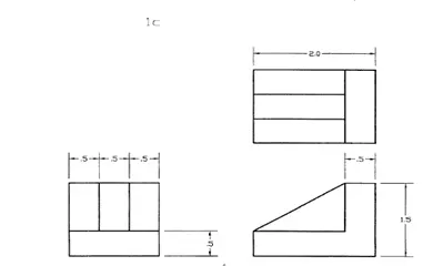
Fig. 25
Procedure followed for drawing Element of Fig. 25:
- Select the current drawing units as decimal.
- Select line command from the toolbar.
- Specify the first point for the line.
- Specify in the length of the line as 1.5 keeping direction horizontal (towards right) (Otho must be on) and Press enter.
- Specify in the length of the line as 1.5 keeping direction vertically upward (Otho must be on) and Press enter.
- Specify in the length of the line as 1.5 keeping direction horizontal (towards left) and Press enter.
- Specify in the length of the line as 1.5 keeping direction vertically downward (Otho must be on) and Press enter. Press “ESC”.
- Select offset command from the toolbar. Specify offset as 0.5 and press enter. Click on the vertical side face of the box drawn and then press left button on the mouse inside the box.
- Now, click on the new created line and then drag the cursor to the right side of the line and then press left button on the mouse.
- Now, click on the bottom line of box and move cursor above that line and press left button on the mouse. Now press “ESC”.
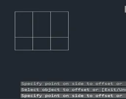
Fig. 26
- Select trim command from toolbar.
- Click on the unwanted portion of the line in order to delete it.
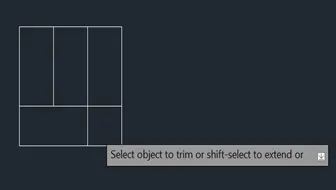
Fig. 27
- Select line command from the toolbar.
- Specify the first point for the line at same level as the bottom of first drawn image.
- Specify in the length of the line as 2.0 keeping direction horizontal (towards right) (Otho must be on) and Press enter.
- Specify in the length of the line as 1.5 keeping direction vertically upward (Otho must be on) and Press enter.
- Specify in the length of the line as 0.5 keeping direction horizontal (towards left) and Press enter.
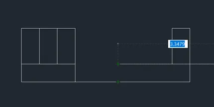
Fig. 28
- Specify in the length of the line as 1.0 keeping direction vertically downward (Otho must be on) and Press enter.
- Press “c” and press enter.
- Select line command from the toolbar.
- Select the left side of the bottom rectangular part of the drawing as the reference for the first point for the line.
- Specify in the command box @0.5<270. Then press “enter”.
- Specify in the command box @2<0. Then press “enter”.
- Specify in the command box @1.5<90. Press “enter”.
- Specify in the command box @0.5<180. Press “enter”.
- Specify in the command box @1.5<270. Press “enter”. Press “ESC”.
- Select the offset command from the toolbar. Specify the offset as 0.5 and press “enter”.
- Select the vertical face of the drawing and drag the cursor to the left side of the drawing and press left button on the mouse.
- Select the line command from the toolbar.
- Select first point drawn in this drawing as the first point for the line.
- Specify in the command box @1.5<0 and press enter.
- Select the offset command from the toolbar and specify offset distance as 0.5 and press enter.
- Click on the last drawn horizontal line and move cursor above the line and press left button on the mouse.
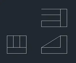
Fig. 29
- Select line command from the toolbar and connect the left face selecting one end and the other end.
- To specify dimensions on the drawing, select linear command from annotation toolbar. Click on the start point and end point of the line for which dimension is required to be specified.
- Repeat the same process for every line so as to show the dimensions.
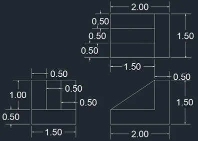
Fig. 30
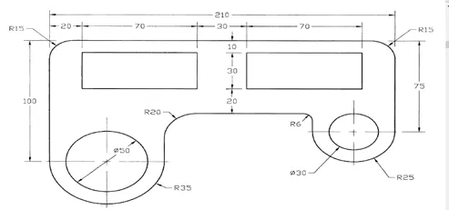
Fig. 31
Procedure followed for drawing Element of Fig. 31:
- Select the current drawing units as decimal.
- Select polyline command from the toolbar.
- Specify the first point for the line.
- Specify in the length of the line as 210 keeping direction horizontal (towards right) (Otho must be on) and Press enter.
- Specify in the length of the line as 75 keeping direction vertically downward (Otho must be on) and Press enter.
- Specify in the length of the line as 25 keeping direction vertically downward (Otho must be on) and Press enter.
- Specify in the length of the line as 50 keeping direction horizontal (towards left) and Press enter.
- Specify in the length of the line as 25 keeping direction vertically upward (Otho must be on) and Press enter.
- Specify in the length of the line as 15 keeping direction vertically upward (Otho must be on) and Press enter.
- Specify in the length of the line as 90 keeping direction horizontal (towards left) and Press enter.
- Specify in the length of the line as 40 keeping direction vertically downward (Otho must be on) and Press enter.
- Specify in the length of the line as 35 keeping direction vertically downward (Otho must be on) and Press enter.
- Specify in the length of the line as 70 keeping direction horizontal (towards left) and Press enter.
- Specify in the length of the line as 35 keeping direction vertically upward (Otho must be on) and Press enter.
- Specify in the length of the line as 100 keeping direction vertically upward (Otho must be on) and Press enter. Press “ESC”.
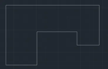
Fig. 32
- Select fillet command from the toolbar.
- Select radius in the command box.
- Now specify the radius for top left corner as 15 and press enter and the click on the lines one by one where curve is required with this diameter.
- Then, similarly specify the radius for the top right corner by selecting the right top corner.
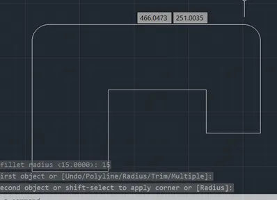
Fig. 33
- Select fillet command from the toolbar.
- Select radius in the command box.
- Now specify the radius for bottom left box as 35 and press enter and the click on the lines one by one where curve is required with this diameter.
- Select fillet command from the toolbar.
- Select radius in the command box.
- Now specify the radius for bottom right box as 25 and press enter and the click on the lines one by one where curve is required with this diameter.
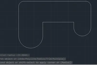
Fig. 34
- Select the line command from the toolbar.
- Locate the position as 20 from the corner in horizontal direction and 10 in vertical direction.
- Select rectangle command from the toolbar. Specify the last located point as the base of rectangle.
- Specify “d” for dimensions. Specify 70 against length and press enter.
- Specify width as 30 and press enter. Specify the position of rectangle as required in the drawing.
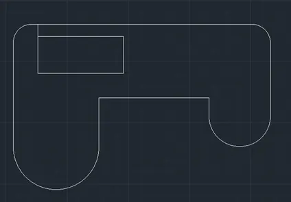
Fig. 35
- Select copy command from the toolbar and then select the rectangle.
- Select the corner of the rectangle as base point for copying the element. Then specify distance (keeping cursor towards right side in horizontal direction) as100 and press enter. Press “ESC”.
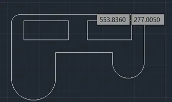
Fig. 36
- Now, select circle command from the toolbar.
- Select the centre of the left semicircle as the centre of circle and press “d” to specify diameter. Then press enter.
- Now, give the value of diameter as 50 and press enter.
- Again, select circle command from the toolbar.
- Select the centre of the right semicircle as the centre of circle and press “d” to specify diameter. Then press enter.
- Now, give the value of diameter as 30 and press enter.
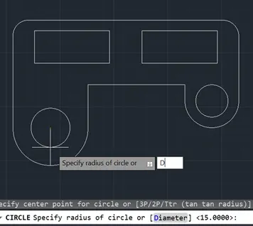
Fig. 37
- Select fillet command from the toolbar.
- Select radius in the command box.
- Now specify the radius for left inner corner as 20 and press enter and the click on the lines one by one where curve is required with this diameter.
- Select fillet command from the toolbar.
- Select radius in the command box.
- Now specify the radius for right inner corner as 6 and press enter and the click on the lines one by one where curve is required with this diameter.
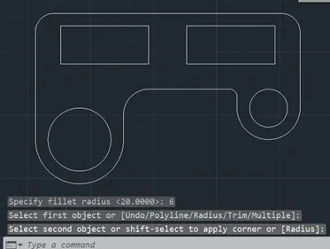
Fig. 38
- Now, click on the new created line and then drag the cursor to the right side of the line and then press left button on the mouse.
- Now, click on the bottom line of box and move cursor above that line and press left button on the mouse. Now press “ESC”.
- To specify dimensions on the drawing, select linear command from annotation toolbar. Click on the start point and end point of the line for which dimension is required to be specified.
- Repeat the same process for every line so as to show the dimensions.
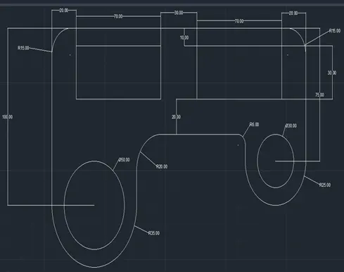
Fig. 39
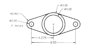
Fig. 40
Procedure followed for drawing Element of Fig. 40:
- Select the current drawing units as decimal.
- Now, select circle command from the toolbar.
- Select the centre of circle and press “d” to specify diameter. Then press enter.
- Now, give the value of diameter as 4 and press enter.
- Again, select circle command from the toolbar. Keeping the centre of circle to be same specify the diameter as 5 and press enter.
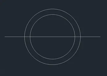
Fig. 41
- Select circle command from the toolbar.
- Specify the first point for the line as the centre of circle.
- Specify in the command box as @4.725<0 and press enter.
- Again, select line command and centre of the circle as start point.
- Specify in the command box as @4.725<180 and press enter.
- Select circle command from the toolbar.
- Select one end of the line as the centre of the circle.
- Specify the diameter as 0.9 and press enter.
- Again, repeat the same command keeping another end of the line as the centre of circle and specify the diameter as 0.9 and press enter.
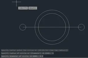
Fig. 42
- Select circle command from the toolbar again.
- Select one end of the line as the centre of the circle.
- Specify the diameter as 1.8 and press enter.
- Again, repeat the same command keeping another end of the line as the centre of circle and specify the diameter as 1.8 and press enter.
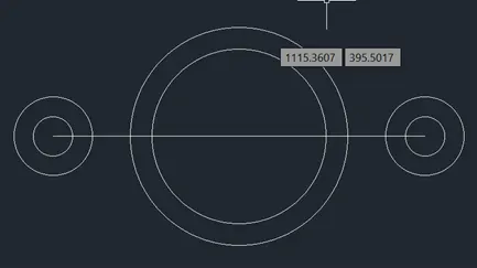
Fig. 43
- Turn on tangent command from snap setting turning off the other settings.
- Draw tangent from one circle to another circle and repeat the same process to connect the exterior circles to connect with interior circles.
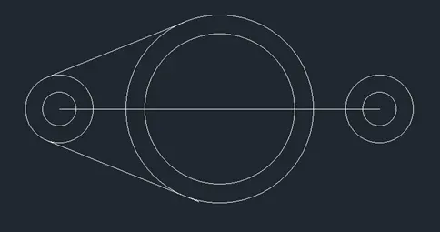
Fig. 44
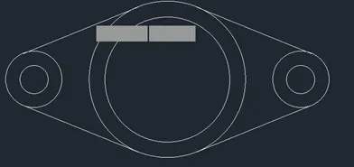
Fig. 45
- To specify dimensions on the drawing, select linear command from annotation toolbar. Click on the start point and end point of the line for which dimension is required to be specified.
- Repeat the same process for every line so as to show the dimensions.
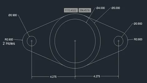
Fig. 46
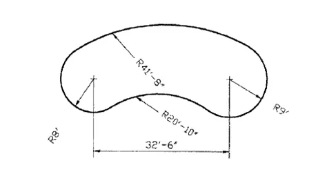
Fig. 47
Procedure followed for drawing Element of Fig. 47:
- Select the current drawing units as architectural.
- Select line command from the toolbar.
- Select the first point to draw the line.
- Specify the length of line in horizontal direction as 32’-6”.
- Now, select circle command from the toolbar.
- Select the left end of the line as centre of circle.
- Now, give the value of radius as 8’ and press enter.
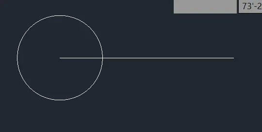
Fig. 48
- Now, select circle command from the toolbar.
- Select the right end of the line as centre of circle.
- Now, give the value of radius as 9’ and press enter.
- Select tangent command in snap setting.
- Select polyline from the toolbar.
- Select radius in the command box.
- Specify the radius as 41’-8” and connect the two circles from the top.
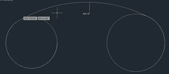
Fig. 49
- Select polyline from the toolbar.
- Select radius in the command box.
- Specify the radius as 20’-10” and connect the two circles from the bottom.
- To specify dimensions on the drawing, select linear command from annotation toolbar. Click on the start point and end point of the line for which dimension is required to be specified.
- Repeat the same process for every line so as to show the dimensions.
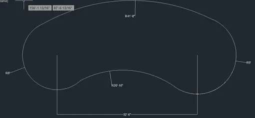
Fig. 50
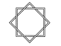
Fig. 51
Procedure followed for drawing Element of Fig. 51:
- Select the current drawing units as decimal.
- Select rectangle command from the toolbar.
- Specify the starting point for the rectangle.
- Select “d” for the dimensions.
- Specify 10 (assumed) against length and press enter.
- Specify 10 (assumed) against width and press enter.
- Select offset command from the toolbar.
- Specify offset value as 0.3 and press enter.
- Now, click on the boundary of the rectangle and then move the cursor inside the rectangle and press left button on the mouse.
- Select copy command and make a copy of rectangle next to it.
- Select rotate command from the toolbar and rotate one of the rectangles at 450.
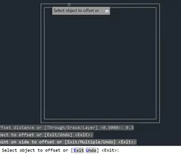
Fig. 52
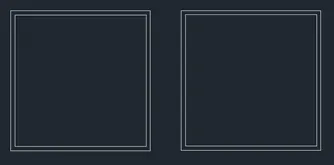
Fig. 53
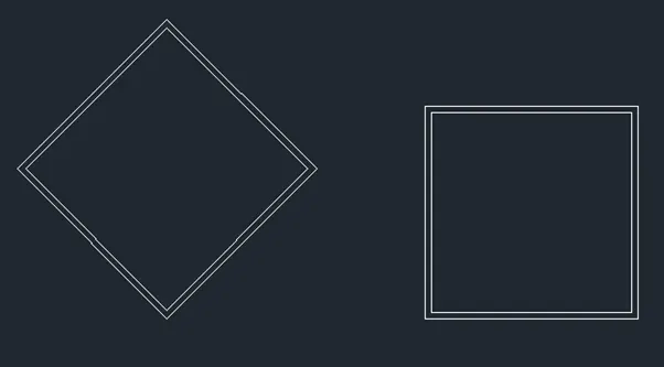
Fig. 54
- Select line command from the toolbar.
- Draw the diagonals for both the rectangle so as to find the centre of the rectangle.
- Select move command from the toolbar.
- Select the rectangle which has been rotated at 450.
- Select the intersection point of the diagonals as base point of moving the object.
- Now cleck on the point of intersection of the diagonals of the other rectangle.
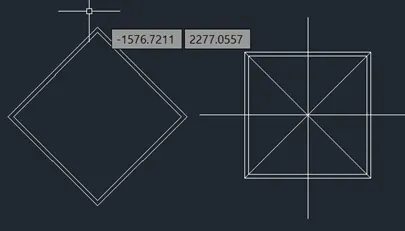
Fig. 55
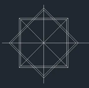
Fig. 56
- Select all the diagonals and press delete to remove them.
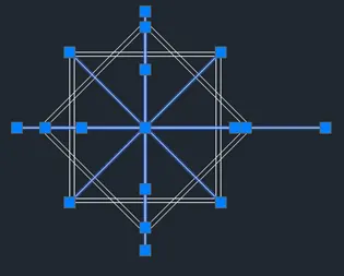
Fig. 57
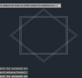
Fig. 58
- Select trim command from the toolbar.
- One by click on the overlapping part so as to remove the unwanted portion as given in Fig. 51.
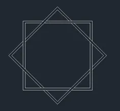
Fig. 59
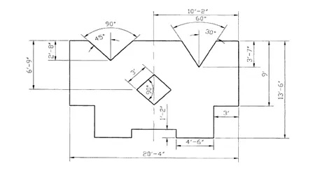
Fig. 60
Procedure followed for drawing Element of Fig. 60:
- Select the current drawing units as architectural.
- Select polyline command from the toolbar.
- Specify the first point for the line.
- Specify in the command box @9’<270 and Press enter.
- Specify in the command box @3’<0 and Press enter.
- Specify in the command box @4’-6”<270 and Press enter.
- Specify in the command box @4’-6”<0 and Press enter.
- Specify in the command box @1’-2”<90 and Press enter.
- Specify in the command box @5’-4”<0 and Press enter.
- Specify in the command box @1’-2”<270 and Press enter.
- Specify in the command box @4’-6”<0 and Press enter.
- Specify in the command box @4’-6”<90 and Press enter.
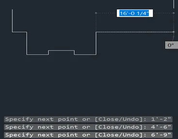
Fig. 61
- Specify in the command box @3’<0 and Press enter.
- Specify in the command box @9’<270 and Press enter.
- Press “c” and enter.
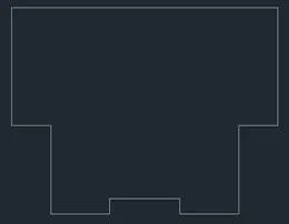
Fig. 62
- Select the current drawing units as architectural.
- Select line command from the toolbar.
- Specify the first point for the line as the centre of the top face of the box.
- Specify in the command box @6’-9”<270 and Press enter.
- Specify in the command box @2.12’<180 and Press enter.
- Now turn on polar coordinate system of 0,45,90..
- Then, keeping the line inclined at 450 and specify the distance at 3’ and press enter.
- Now, again keep the line at 450 so that it has an angle of 900 with the previous line, specify the distance as 3’ and press enter.
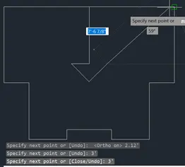
Fig. 63
- Now, again keep the line at 450 so that it has an angle of 900 with the previous line, specify the distance as 3’ and press enter.
- Now, again keep the line at 450 so that it has an angle of 900 with the previous line, specify the distance as 3’ and press enter. Press “ESC”.
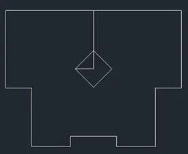
Fig. 64
- Now, select the extra drawn lines and press delete.
- Select offset command from the toolbar.
- Specify the offset as 2’-8” and press enter. Click on the top face of the box then move the cursor inside the box and press left button on the mouse.
- Select offset command from the toolbar.
- Specify the offset as 3’-7” and press enter. Click on the top face of the box then move the cursor inside the box and press left button on the mouse.
- Select line command from the toolbar.
- Select the first point of line as the centre of the half of the top face.
- Specify in the command box @2’-8”<270 and press enter.
- Keeping angle as 450 (towards right) draw the line cutting the top face.
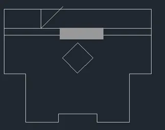
Fig. 65
- Select line command from the toolbar.
- Select the first point of line the bottom of the vertical line drawn for reference.
- Keeping angle as 450 (towards left) draw the line cutting the top face.
- Select the unwanted vertical line and then press delete.
- Select trim command from the toolbar and remove the extra portion of the line.
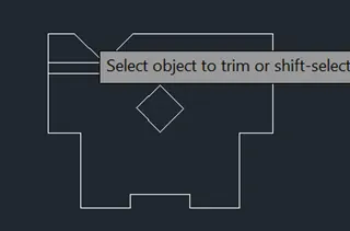
Fig. 66
- Select line command from the toolbar.
- Select the first point of line as the centre of the right half of the top face.
- Specify in the command box @3’-7”<270 and press enter.
- Keeping angle as 450 (towards right) draw the line cutting the top face.
- Select line command from the toolbar.
- Select the first point of line the bottom of the vertical line drawn for reference.
- Keeping angle as 450 (towards left) draw the line cutting the top face.
- Select the unwanted vertical line and then press delete.
- Select trim command from the toolbar and remove the extra portion of the line.
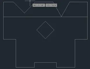
Fig. 67
- To specify dimensions on the drawing, select linear command from annotation toolbar. Click on the start point and end point of the line for which dimension is required to be specified.
- Repeat the same process for every line so as to show the dimensions.
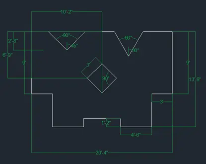
Fig. 68