Creating a Residence Layout, Seating plan, Toilet and Utility room plan using AutoCad
CHALLENGE-4
PREPARED BY- MEGHA GUPTA
Creating a residential layout, seating plan, toilet and utility room plan using AutoCAD.
Aim: Aim of the challenge is to create the layout for a residential building plan, seating plan and toilet and utility room plan in AutoCAD.
Introduction: In this project various plans have been created using various tools available in AutoCAD.
Residential building plan was created using engineering unit system whereas the remaining two were created using decimal system. All the required tools have been used in the creation of these plans like offset, trim, extend, fillet, line, rectangle, annotation etc. The plan has been created different layers and bylayers in order to make things simple and separate them.
Procedure followed for creating the plans has been discussed below with each of the drawing.
- Sketch the layout of a residential building shown in Fig. 1. Consider all dimensions as reference to sketch the unit plan. Also, the text in the layout are only for reference. Assume the missing dimensions. Also, refer the schedule for the size of doors.
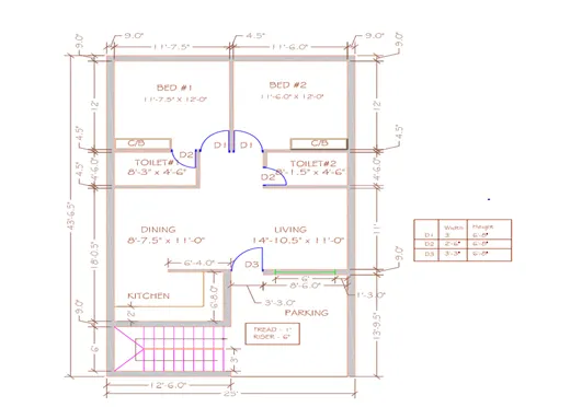
Fig.1: Residential building plan
Procedure followed for drawing Residential plan:
- Select the current drawing units as engineering.
- Select line command from the toolbar.
- Create a layer for wall. And turn it on.
- Specify the first point for the line.
- Specify in the command box @13’-9.5”<90 and Press enter.
- Specify in the command box @9”<90 and Press enter.
- Specify in the command box @11’<90 and Press enter.
- Specify in the command box @4.5”<90 and Press enter.
- Specify in the command box @4’-6”<90 and Press enter.
- Specify in the command box @4.5”<90 and Press enter.
- Specify in the command box @12’-9.5”<90 and Press enter.
- Specify in the command box @9”<90 and Press enter.
- Specify in the command box @9”<180 and Press enter.
- Specify in the command box @11’-6”<180 and Press enter.
- Specify in the command box @4.5”<180 and Press enter.
- Specify in the command box @11’-7.5”<180 and Press enter.
- Specify in the command box @9”<180 and Press enter.
- Specify in the command box @9”<270 and Press enter.
- Specify in the command box @12’<270 and Press enter.
- Specify in the command box @4.5”<270 and Press enter.
- Specify in the command box @4’-6”<270 and Press enter.
- Specify in the command box @4.5”<270 and Press enter.
- Specify in the command box @18’-0.5”<270 and Press enter.
- Specify in the command box @9”<270 and Press enter.
- Specify in the command box @6’<270 and Press enter.
- Specify in the command box @9”<270 and Press enter.
- Specify in the command box @12’-6”<0 and Press enter.
- Press “c” and enter.
- Select offset command from the toolbar.
- Specify offset as 9” and press enter.
- Now one by one select all the outer walls having thickness of 9” and moving cursor inside the plan press left button on the mouse.
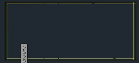
Fig. 2
- Now, select line command from the toolbar.
- Draw inner walls as given in the plan (referring Fig. 1) Use offset command to give their thickness as 4.5”.
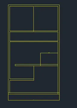
Fig. 3
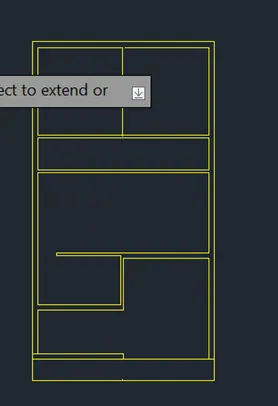
Fig. 4
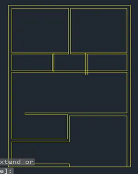
Fig. 5
- Select all the extra line and remove them by using trim command from the toolbar.
- Use line command to draw the staircase. Then use offset command to create all the steps at 1’ spacing in the plan as the tread is 1’.
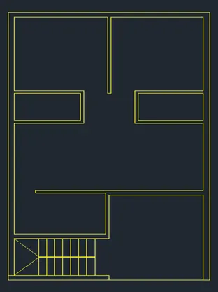
Fig. 6
- Select offset command from the toolbar.
- Specifying offset as 2’ draw the shelf for the kitchen.
- Use trim command to remove the overlapping or extra portion of the lines.
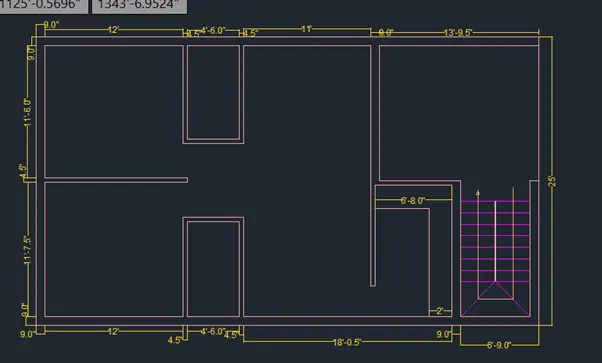
Fig. 7
- Create a new layer for doors.
- Now, select line command to draw the doors as per the schedule.
- D1 door has a width of 3’ which must be visible in the plan, to create that line command will be used.
- To show the direction of opening the door and its rotation circle.
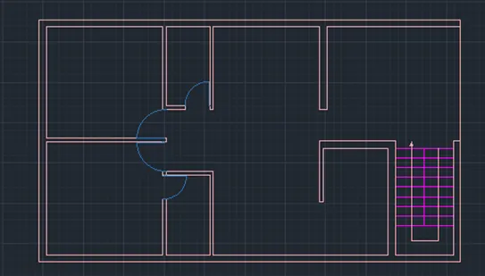
Fig. 8
- Now, select annotation text command to write the details. This will be done under text layer.
- Click inside the room and specify the dimensions using annotation command.
- Turn on the dimension layer.
- Using linear dimension command from the tool bar to specify the dimensions of different parts of the plan.
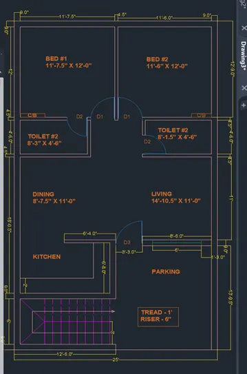
Fig. 9
- Now, using annotation text command create the table for door schedule. Here I have used a bylayer for changing the colour of the text.
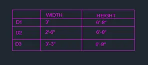
Fig. 10
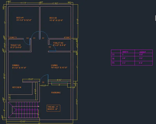
Fig. 11: Residential building plan with door schedule
- Sketch the seating plan for an outdoor canopy. Assume the dimensions for the seating. Also, consider the dimensions in mm.
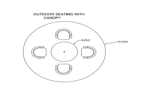
Fig. 12
Procedure followed for drawing sketch of seating plan with canopy:
- Select the current drawing units as decimal.
- Select circle command from the toolbar.
- Select the centre of the circle and specify radius as 1398 and press enter.
- Again, select the circle command from the toolbar.
- Selecting the same centre for the circle, specify the radius as 452 and press enter.
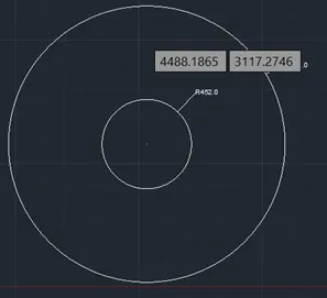
Fig. 13
- Now, to create the chair, select line command from the toolbar.
- Create a rectangle.
- Then select circle command from the toolbar selecting centre of the circle as the centre of back face of the rectangle with diameter same as that of length.
- Select trim command from the toolbar, and remove the front half of the circle and delete the unwanted line also.
- Select fillet command from the toolbar.
- Now, select the lines one by one so as to create the smooth curved surface at the corners.
- Now, select the offset command. Using offset create the back and hand rest for the chair.
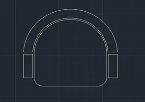
Fig. 14
- Select circle command from the toolbar and keeping same centre as other circles specify the radius as 600 and press enter.
- Now draw lines passing from the centre of circle so as to divide the circle in four parts.
- After creating a chair, it has to be placed at 4 sides as given in the Fig. 12.
- Select copy command and select the chair.
- Now, select the centre of the of the front face of the as base point and paste at the intersection point of circle and line drawn for reference.
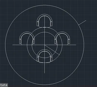
Fig. 15
- Now, select each chair one by one and rotate them in such a way that the chair is facing table.
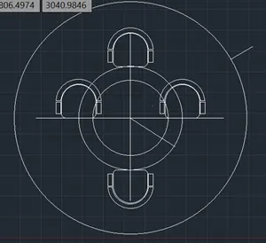
Fig. 16
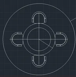
Fig. 17
- Select the circle and lines drawn just for the reference and delete them.
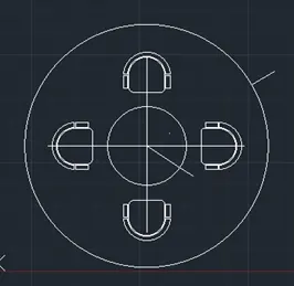
Fig. 18
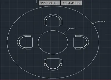
Fig. 19
- Sketch the part plan for the toilet and utility room. Consider the outer wall thickness as 300 mm and inner wall thickness as 150 mm. Also, assume the missing dimensions, texts, dimensions and hatches are only for references. Also, symbols for toilets and w/c are for references.
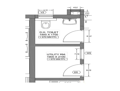
Fig. 20
Procedure followed for drawing toilet and utility room plan:
- Select the current drawing units as decimal.
- Select line command from the toolbar.
- Specify the first point for the line.
- Specify in the command box @1700<270 and Press enter.
- Specify in the command box @150<270 and Press enter.
- Specify in the command box @2100<270 and Press enter.
- Extend this line by 20 mm further to show the continuation of wall.
- Again, draw the line selecting the inner corner of the utility room wall as reference as per Fig. 20.
- Specify in the command box @1900<0 and Press enter.
- Specify in the command box @1700<90 and Press enter.
- Specify in the command box @150<90 and Press enter.
- Specify in the command box @2100<90 and Press enter.
- Press “c” and enter.
- Select line command from the toolbar.
- Select top right corner of the plan as first point to draw the line.
- Specify in the command box @201<90 and Press enter.
- Specify in the command box @402<180 and Press enter.
- Specify in the command box @201<270 and Press enter.
- Select offset command from the toolbar and specify the offset as 150 and press enter.
- Referring Fig. 20, provide the offset for the walls having thickness of 150mm.
- Select offset command again and specify the offset as 300 and provide the thickness for the outer walls as 300mm.
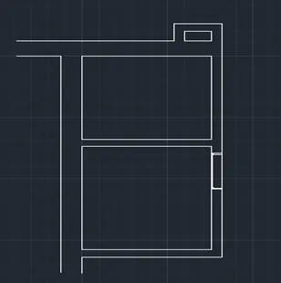
Fig. 21
- Now, use line command to create doors and to remove unwanted portion use trim command.
- Use, circle command from the toolbar to show the rotation of circle.
- Use line command from the toolbar, to create the window and ventilator.
- w/c and basin has been created using line, circle and trim commands.
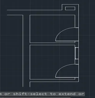
Fig. 22
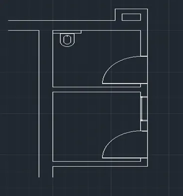
Fig. 23
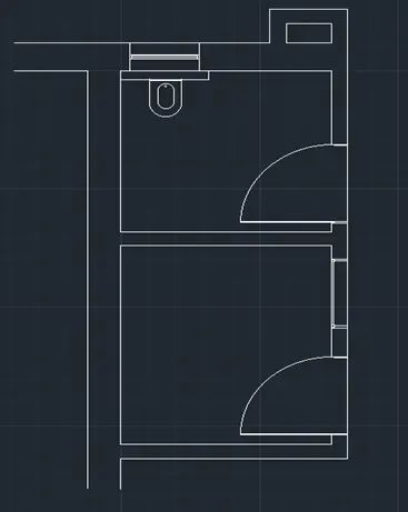
Fig. 24
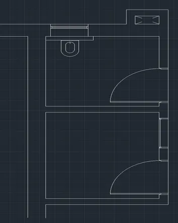
Fig. 25
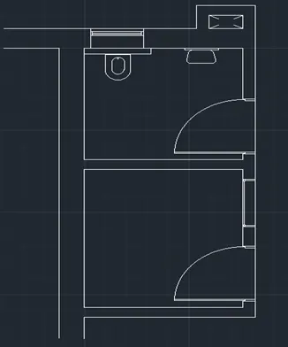
Fig. 26
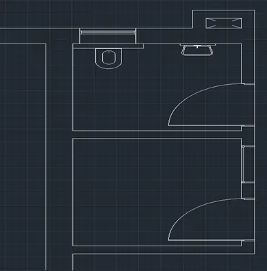
Fig. 27
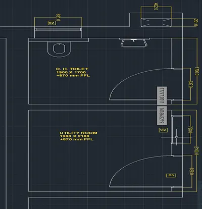
Fig. 28
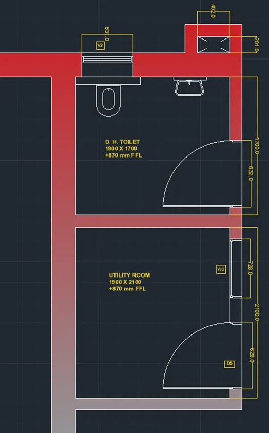
Fig. 29