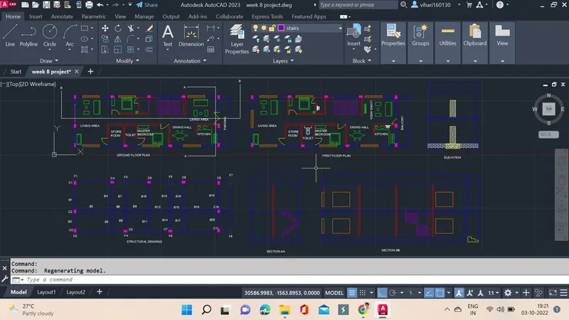
Project 1 _Creating an Architectural plan for the provided plot size and develop relevant basic structural drawings
AIM: To design and draft a layout of a residential building with the following details:a. Plot Size: 60’x20’(18.3m x6m)
b. Orientation- Facing East
c. Develop the following: 1. Architectural Drawing (Floor Plan, Elevations, and Sections) 2. Structural Drawing (Column, Bean, Footing Plan)
INTRODUCTION: Autocad software is basic and very important software used in the design and drafting the 2D and 3D structural buildings in the construction field. In this project we are going to use the following commands
- L line command to draw lines.
- ARC command is used to draw when required near doors.
- CO copy command to copy the objects.
- M move command is used to move the objects if required.
- RO rotate command is used when a object is copied and need to orient its position.
- REC rectangle command is used to draw the rectangles whenever required.
- LAYER is used to create layers to identify the individual walls and structural elements.
- DIMSTY a command used to specify the dimensions.
- DIMLIN is used to give the dimensions.
- H hatch command is used to hatch the required areas like concrete, brick work.
Procedure:
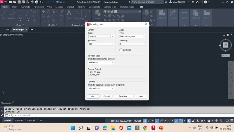
1. Open CAD software new file is created and then unit are specified to decimal.
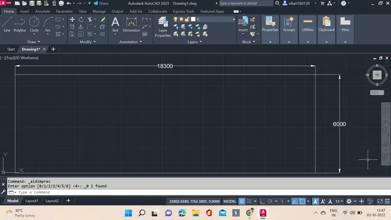
2. The next step is create the plot using the given specifications as 18.3m x 6m.
3. REC command is used and then dimensions are selected then length is given as 18300 and the width is given as 6000.
4. DIMLIN command is used and the dimensions are mentioned.
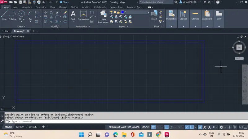
5. Architectural plan is made first using Layer command in order to specify the external walls and interna walls differently to identify quickly.
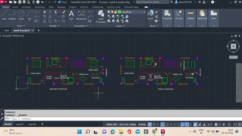
6. This plan consists of two floors ground floor, first floor with opening facing east according to the given plan.
7. Layer is opened a colour is specified and external walls name is specified and then O offset command is used and then 250mm is drawn inside the present rectangle.
8. Layer is opened a colour is specified and internal walls name is specified, next the rooms are divided into bedroom, kitchen, dining, living room etc.
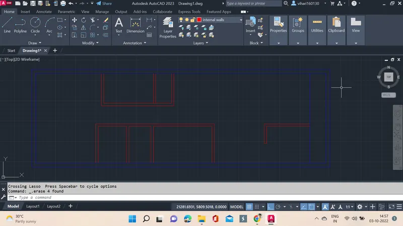
9. A layer is created a colour is specified and staircase is drawn for connecting ground and first floor.
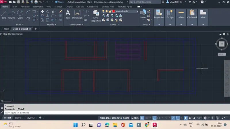
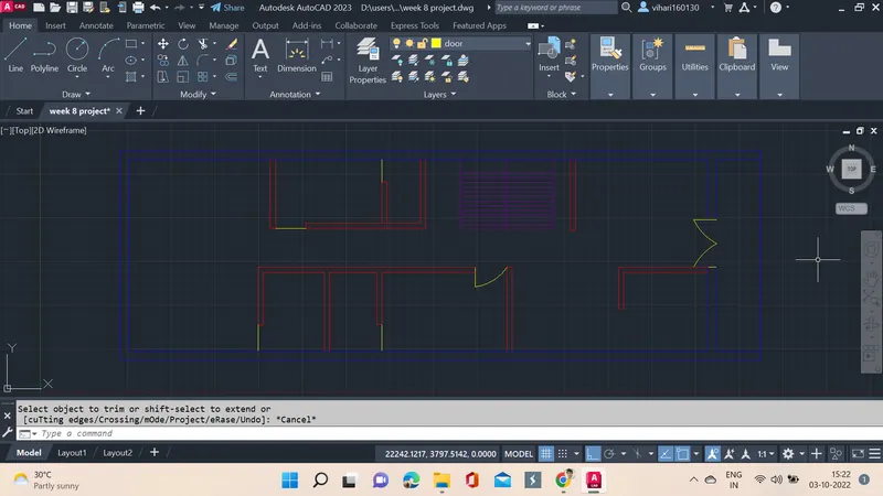
10. Now openings are made then doors are kept using anothher colour another layer.
11. Now windows are drawn using another colour another layer.
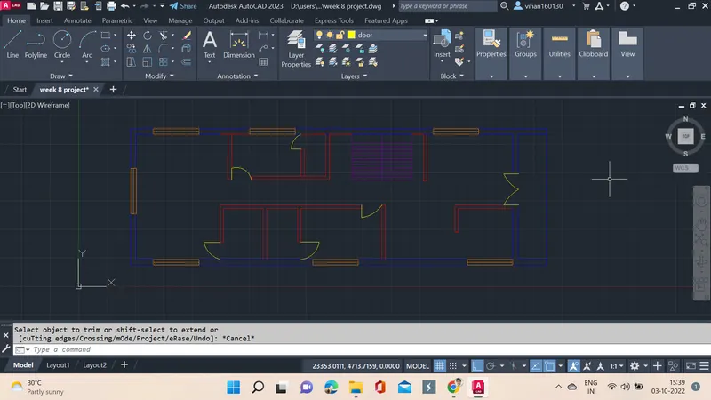
12. Some detailings like kitchen room is done, living room sofa is drawn.
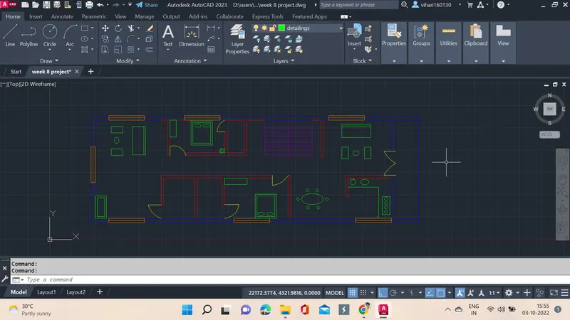
13. Columns are placed in the respective places.
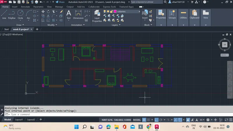
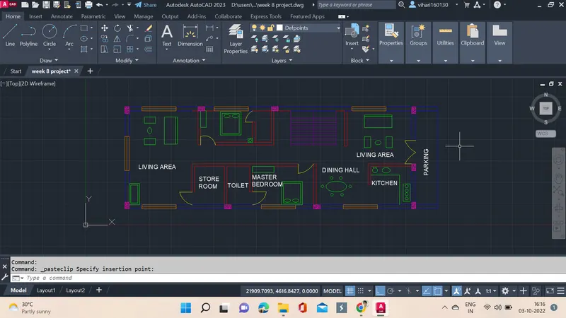
13. The MTEXT command is used to give texts and then ground floor is completed.
14. The process is almost the same for first floor plan so the steps are repeated and then the final first floor is as below.
15. Only change is that in place of parking balcony is drawn.
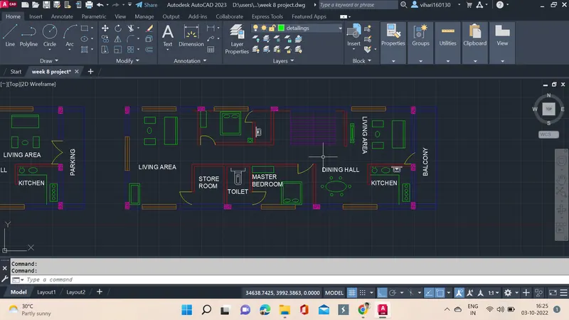
16. Architectural drawings are drawn for both floors.
17. Elevation is made for both floors using external walls layer itself.
18. L command is used to draw the elevation, first a point is specified and then a line is drawn using @6000,0.
19. next point is specified as @0, 600 and line is drawn, next point is specified as @-250,0 and a line is drawn.
20. next point is specified as @0,3060 and line is drawn, next point is specified as @-5500,0 and a line is drawn.
21. next point is specified as @0,3060 and line is drawn, next point is specified as @250,0 and a line is drawn.
22. next point is specified as @0, 1000 and line is drawn, next point is specified as @-6000,0 and a line is drawn.
23. the missed lines are joined and elevation is completed.
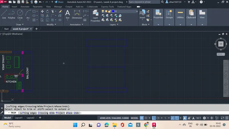
24. Small detailings are added and H hacthing is used hatch command is used.
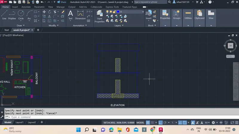
25. This step is to draw the structural elements like beam, columns, footing at respective places.
26. Using CON command construction line is used to draw the lines respectively with the columns.
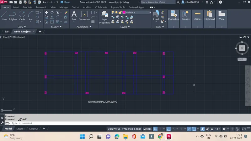
27. next step is to draw footings at respective places.
28. next stop is to draw the beams at the respective places.
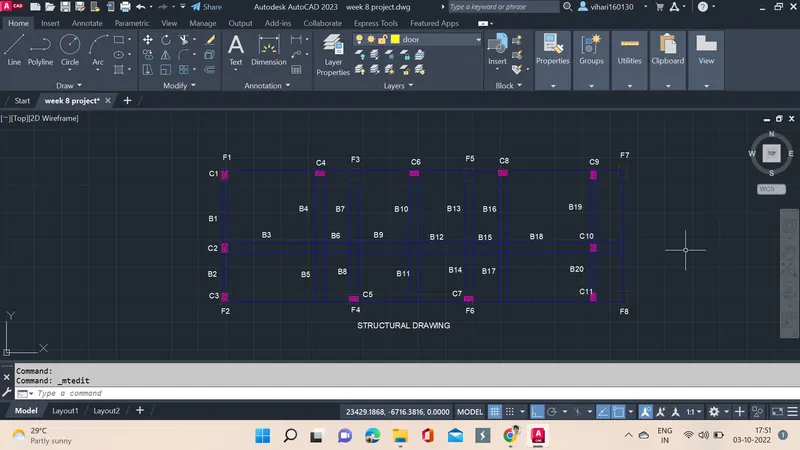
29. the final step is to draw the section drawings of AA and BB.
30. First AA section is drawn taking the elevation as base.
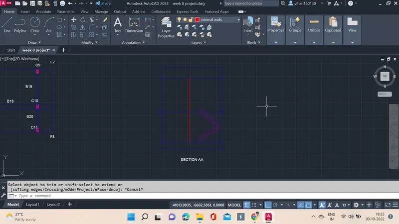
31. Section-BB is now drawn.
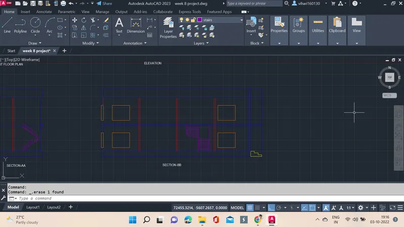
32. sectional drawings are also completed.
RESULT: A residential building is drawn which has plot size 18.3m x 6m, architectural drawing is drawn in which floor plans, elevation and sections, other than that structural drawing is drawn which consists of column, beam, footing plan are drawn using the AUTOCAD software.