Sketch a G+1 residential plan according to Vaastu Shastra and Calculation of Loads as per IS code
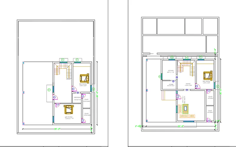
Residential plan, according to Vaastu Shastra:
- For a house to become a home, it needs to radiate the right kind of energy.
- According to a number of traditional beliefs, each home comes with its own energy type.
- A person dwelling in a house comes under the influence of a specific energy field, which in turn influences him in one way or the other.
- Therefore it's very crucial to understand the link between the healing art of Vastu and our homes in honing positivity and good vibes.
Tahe Vaastu shastra requirement/ needs to be followed for a house project :
Direction of the House
- According to vastu shastra, the entrance to a house is not meant just for people but also for energy.
- Energies flow in and out through the main door.
- The main entrance of house is East.
- Make sure you check this before you purchase your new home.
Direction Should the Rooms Face
- Kitchen: The kitchen placed in the south-east direction of the house. Never buy a house where the kitchen is built in the north direction.
- Master bedroom: The master bedroom should be built in the south-west direction.
- Dinning room: The placed in the south-west direction at home.
- Toilet: According to vastu shastra, the toilet/bathroom should be located in the west and north-west direction.
- Store Room: The Store room placed in the south-east direction of the house.
Shapes and Forms
- Vastu shastra experts also spell out guidelines on the shape of your rooms.
- Although circular rooms look more stylish and trendy, they are not compliant with vastu.
- Make sure your rooms follow strict lines and are square or rectangle in shape.
The Overhead Water Tank be Installed
- Ideally, the overhead water tank should be placed in the west or south-west direction of the house.
- If you place it in the south-west direction then make sure you place it two feet above the topmost slab.
The list of drawings that is mandatory to be provided to the site :
- A construction drawing or plan illustrates what you will build and what the finished product will look like when you complete it, but there are different types of construction drawings used.
- The types of drawings, such as blueprints, plans, working drawings, and are quite confusing.
- As with any complex document, the different types of commercial construction drawings require specialty skills to decipher.
1. Architectural Drawings:
- This is one of the types of construction drawings. It provides a complete view of a building.
- There several design programs out there but nothing like 3-D and 2-D Modeling can give architects and designers a more accurate example to articulate the end-product needed for the subcontractors to build.
- An architectural drawing is a technical rendition of a building (or building project) that falls within the classification of architecture.
- Historically, architectural drawings were made in ink on paper or similar material, and copies require an expensive printer that needs to be expensively hand delivered.
- If you’re still operating with a tremendous amount of paper, imagine the construction saving a digital ecosystem.
2. Structural Drawings:
- This type of construction drawing provides a complete view of the structure or structures involved in the building project.
- Structural drawings are typically prepared by licensed structural engineers relying on input from architectural drawings.
- Structural drawings emphasize load-carrying members (e.g., steel beams, joists, framing materials, and so forth) of the structure.
- Structural construction drawings are unique to other drawings because they do not address partition walls, plumbing, and mechanical systems, or other details like surface finishes.
- We prepare the structural model to find the reinforcement bars and claculate tha load calculation.
- the we ready a footing drawing and footing reinforcement details.
- The we give a each element for structural reinforcement bar details.
- Give a excavation plan and deapth of excavation all deails to site engineers.
4. Electrical Drawings:
- This type of technical drawing illustrates information about lighting, wiring, power, and circuits for communication within the commercial construction project.
- Electrical construction drawings are meant to illustrate the physical layout of the wires and components they connect inside the building as well as the outside power grid.
- Standard schema symbols in electrical drawings represent circuit breakers, transformers, capacitors, bus bars, conductors, and many other details on drawings.
- Electrical contractors spend years mastering their craft and deserve software to make their jobs easier.
5. Plumbing and Sanitary Drawings:
- This type of technical drawing illustrates the system for pumping water in and out of the building.
- Equipment, pipes, pumps, and drains, the nature and size of sinks to the location of gas are carefully illustrated in a drawing.
- Plumbing construction drawings also indicate the position of sanitary, piping for water supply system, fixtures, and the process to connect every accessory.
- Read this article on how to save thousands of dollars a year with digital blueprint.
6. Finishing Drawing:
- This drawing illustrates the finishing details and appearance of the building.
- Construction Finishing drawings include every type of components of the building, such as painting colors, flooring pattern, plastering texture, elevation design, and false ceiling shapes.
- The drawing a completed and issued to site for revisied drawing given a name by revision 0 and revision 1.
Load calculation:
All columns are 300mm x 300mmx2.5m
- All beams are 300mm x 450mmx400mm
- Slab thickness if 125mm
- The height of the wall is 4.5m
LIVING ROOM:
DL For Column=0.3x0.3x2.5x25 =5.625kN
DL For Beam =0.3x0.45x0.4x25 =1.35kN
DL For Wall =3.7x20x0.23 =17.02kN/m
DL For Slab =.125x25 =3.125kN/m2
LL For Slab =2KN/m2
KITCHKEN ROOM:
DL For Column=0.3x0.3x2.5x25 =5.625kN
DL For Beam =0.3x0.45x0.4x25 =1.35kN
DL For Wall =3.7x20x0.23 =17.02kN/m
DL For Slab =0.125x25 =3.125kN/m2
LL For Slab = 2kN/m2
BEDROOM:
DL For Column=0.3x0.3x2.5x25 =5.625kN
DL For Beam =0.3x0.45x0.4x25 =1.35kN
DL For Wall =3.7x20x0.23 =17.02kN/m
DL For Slab =0.125x25 =3.125kN/m2
LL For Slab = 2kN/m2
BATH ROOM:
DL For Column=0.3x0.3x2.5x25 =5.625kN
DL For Beam =0.3x0.45x0.4x25 =1.35kN
DL For Wall =3.7x20x0.23 =17.02kN/m
DL For Slab =0.125x25 =3.125kN/m2
LL For Slab = 2kN/m2
STORE:
DL For Column=0.3x0.3x2.5x25 =5.625kN
DL For Beam =0.3x0.45x0.4x25 =1.35kN
DL For Wall =3.7x20x0.23 =17.02kN/m
DL For Slab =0.125x25 =3.125kN/m2
LL For Slab = 3kN/m2
NOTE:[Live Load is taken from IS 875 part-2]