Creating a Residence Layout, Seating plan, Toilet and Utility room plan using AutoCad
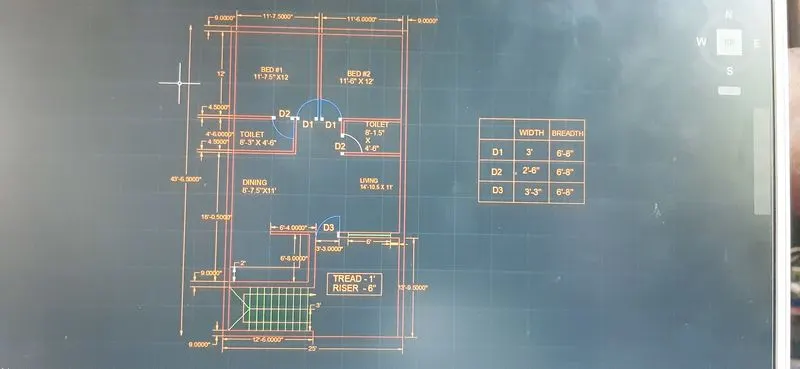
Aim:To draw the layout of the residential plan
Commands used:
- XL-H
- Offset
- fillet
- Extend
- Trim
PROCDURES:
- First create a new Autocad file with imperial settings
- Type ''Engineering'' in units and selects inches
- Set the limits with command ''LIMITS'' specify the left corner points and right corner enter zoom all
- draw construction line by XL-H
- Drawing bed:
- Take offset of construction line by 9'' by using command ''o''
- Take the offset 11'7.5 to the x direction and offset of 12' y direction so that the room is formed
- Again, give the offset to the both lines of 4.5'' so that wall thickness is created
- Trim the unwanted lines
- Drawing bed 2:
- Give offset from the wall thickness of bed 1 towords +x direction of 11'6
- offset the 9'' to create the wall on right side
- Extend the line of 12' from bed1 towords this line command ''EX'' select the line to where it should be extended 4.5'' offset line of bed 2
- Trim the the unwanted lines
- Drawing toilet 1:
- offset 4'6 downwords then also offset 4'5 wall
- Extend the left side wall towords the line 4'6'' and the wall
- From that line offset 8'3'' towords +x direction and offset the wall of 4'5''
- Trim the unwanted lines
- Drawing the toilet 2":
- Extend the wall thickness of bed 2 to the 4'6'' line
- offset a distance of 8'1.5'' towords -x direction and also 4'5'' wall thickness
- Trim the unwanted lines
- Drawing the dining and living room
- Give the offset of 11' from the wall of toilet and also the wall of 9''
- Extend the left wall towords the 11' line and 9'' line
- Use thefillet to jooin this line and the wall of toilet 2
- Give an offset of 8' 7.5 to understand the partition between the dining and living
- Trim of wall thicknedd of dining and offset it as 4.5''
- Drawing kitchen
- Give an iffset from the dining wall of 6'8 and givean oiffset of 9'' for wall thicness
- Extend the left wall towords this line
- Give an offset the wall thickness as 9''
- Drawing parking and staircase room:
- Draw offset 12'6'' to draw the parking, then give offset of 9'' towords inside
- Give offset 13'9.5 from the living wall towords downwords
- Extend both side line towords this line
- Extend both side lines towords this line
- Extend outer wall of kitchen , so that the staircase room is defined
- Drawing staircase:
- Given:Thread :1'
Riser: 6''
- Give a wall thickness of 9'' for the staircase room
- Divide the staircase room by giving offset 3' from the front wall rhickness
- Give an offset of 1'.96 to show the handrail
- Draw offset of 1' to draw the stair in plain view
- Draw 9 offset as there are 9 riser for 8 steps
- Trim the lines between the handrail and give the other side as dotted lines
- For the select the lines and change the line type to iso dash
- Make the direction of staircase
- Drawing doors
- Trim all the doors openings with their resp. width D1-3' ,D2-2'6''.D3-3'3''
- For open kitchen ,trim the line retainng a distance of 6'4'' from the right side of kitchen
- draw the doors creating a hinge of 0.5'' from the midpoint of both the wall , then drawing a circle with one point on the midpoint of one hinge and other the midpojnt of another hinge
- Place the windows
- For living , take an offset of 1'3, this is where the window starts
- using the line command draw a line of 6' from the centre of offset line inside the wall thickness
- Draw the windows wherever necessary : from the middle portion of a wall draw a line from the midpoint of that line give the distance i.e. the width of the window , then join the other side
- Trim all unwanted lines and fillet the corners with fillet radiouszero.compund f'' select both the lines
- Drawing rhe kitchen slab and cupboards
- Offset a distance of 2' to make the kitchen slab
- Draw the ccupboards by creating a reactangle command ''REC'' Specify base point click on dimension and give dimension as 5' x 2'
- Copy the rectangle to another bedroom also
- Placing each component in layer
- From layer property create new layer -create 8 layer each for wall ,door,window ,stairs ,kitchen slab and cupboard
- select the objects and place it in resp. layer
- RESULT
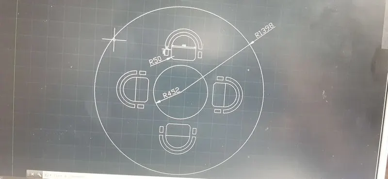
- AIM:To draw the seating plan for an outdoor canopy
- Commands used
- Circle
- offset
- fillet
- extend
- trim
- PROCEDURE
- Select metric unit as dimension in mm
- Draw a circle with a command ''C'' select a centre point and give the radious as 1398mm
- Draw another circle with same centre with radious 452mm
- Draw an offset of 200mm from the inner circle to determine the position of chairs
- Draw lines along the diameter of the bigger circle
- Drawing chairs
- Draw a rectangle with command "'rec"' giving dimension as 400mm and 200mm
- Draw an arc with start cnetre and end method with the end points and centre of the side of rectangle
- draw another rectangle of 55mm X 100mm for the handle of the chair command ''rec'' select the base point and click on dimension and give as 55mm and 100mm
- copy it on the other side so that handles are formed
- fillet the corner of rectangle by 50 mm command ''o'' give the fillet radious as 50mm command ''o'' give the fillet radious as 50 mm and select the two lines and trim off the unwanted lines
- ove the chair and place it such a way that it touches the offset 200mm circle by using command''m'' select the base point and move it
- mirror the chair to the opposite side command mi select the base point and draw the reference line where we need to mirror
- rotate the chair to the opposite side command mi select the base point and draw the reference line where we need to mirror
- rotate the chair and movie it so that the chair in left side is created command ''ro'' select the base point and rotate to desired angle
- again mirror the chair so as to create chair in right side
- delete the line and offset circle
- RESULT
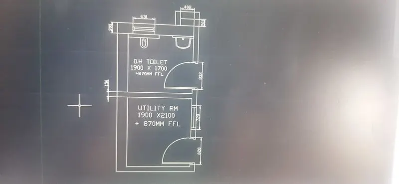
- AIM:To draw a plan for the toilet and utilities room
- Commands used:
- XL-V
- OFFSET
- FILLET
- EXTEND
- TRIM
- DESIGN CENTRE
- PROCEDURE
- First create a new autocad file with metric units
- set the limits with command ''LIMITS'' .Specify the left corner points and right corner points and enter zoom call
- draw construction lines by command XL-V for vertical and both hoorizontal
- trim the unwanted position of the construction line
- drawing the utility room
- draw an offset of 300mm from the left side if vertical construction line and an offset of 150mm from the bottom horizontal construction line
- draw an offset of 2100 mm upwords and offset of 1900mm towords the right side and give the wall thicknessof 150 mm and 300 mm resp.
- Drawing DH Toilet
- Draw an offset of 1700mm upwords and wall thickness of 300 mm as it is ext. wall and a room is formed
- Trim off the rest of the construction line
- create opening for door
- From toilet, after offset of 100mm , give the another offset of 832 mm and trim to form the door opening by creating 12.5 mm hinge and thendraw circle to the midpoint of other side of wall.Trim the rest of circle to form anarc
- Draw window of 728 mm iin the utility room and a ventilator of 631 mmun toilet room
- draw window of 728mm in the utility room and a ventilator of 631mm in the toilet room
- draw the duct shown behind the toilet room by offset at a distance of 201mm and 150mm wall thick wall thickness upwords
- extend the wall of toilet towords it and offset 402 mm,offset wall thickness as 150mm
- Drawing an utility symbols
- In the command line enter ''DS'' and select en-us- homre utility -select the symbols by draging them into autocad screen and place where ever required
- RESULT