Sketch a G+1 residential plan according to Vaastu Shastra and Calculation of Loads as per IS code
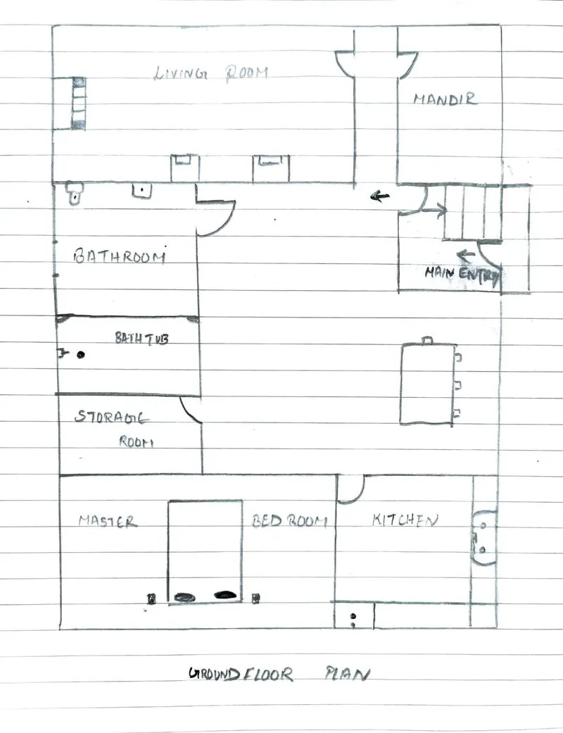
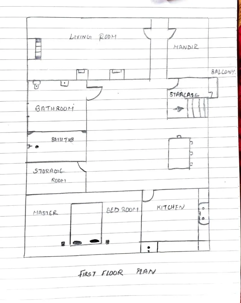
Introduction : Following drawing shown below are the G+1 Residential floor plan according to the Vastu Shastra.
 Lets
Lets
The dimention of the room is given below.
Assume that size of
Master Bedroom : 9m X 7m
Bath : 5m X 7m
Kitchen : 7m X 7m
Living Room : 9m X 8m
Dining Room : 7m X 4m
Balcony : 2m X 4m
Mandir : 3m X 5m
Storage Room : 5m X 4m
Main Entry G.F/ F.F : 4m X 4m
DEAD LOAD CALCULATION :
Lets Assume,
Column length : 0.3m
Column Breadth : 0.3m
Height of Columns : 4m ( wall height)
Volume of Column : 0.36 m^3
No. Of columns : 32 Nos ( 2 Floor Considered)
Unit Weight of RCC Column : 25 KN/m^3
Total Dead Load Of Column : 0.36 X 32 X 25 =288 KN
Lets Assume,
Beam Bredth : 0.3m
Beam Depth : 0.45m
G.F Beam Length : 155m
F.F Beam Length :155m
F.F Balcony Beam : 8m
Total Length of Beam : 318m
Volume of Beam : 0.3 X 0.45 X 318 = 42.93 m^3
Unit Weight of Beam : 25 KN/m^3
Total Dead Load of Beam : 42.93 X 25 = 1073.25 KN
Lets Assume for G.F Slab,
Slab thickness : 0.125m
Slab S1 Length : 16m
Slab S1 Bredth : 24m
Volume of Slab S1 : 0.125 X 16 X 24 = 48 m^3
Here also in F.F Slab,
Slab S2 Length : 16m
Slab S2 Breadth : 24m
Slab Thickness : 0.125m
Volume of Slab S2 : 0.125 X 16 X 24 = 48 m^3
In Balcony Area,
Slab S3 Length : 2m
Slab S3 Breadth : 4m
Slab thickness : 0.125m
Volume of Slab S3 : 2 X 4 X 0.125 = 1 m^3
Total Slab Vol: 48 + 48 + 1 = 97 m^3
Unit Weight of slab : 25 KN/m^3
Total Dead Load Of Slab : 97 X 25 = 2425 KN
Wall height : 4m
Wall thickness : 0.23m
Unit Weight of Brick wall : 20 KN/m^3
Dead Load of the wall : 4 X 20 X 0.23 = 18.40 KN/m
Live Load of the Plan
Bathroom : 2KN/m^3
Kitchen : 2 KN/m^3
Living room : 2 KN/m^3
Balcony : 3 KN/m^3
Store Room : 3 KN/m^3
Corridor / Staircase : 3 KN/m^3
Dining Room : 2 KN/m^3
Mandir : 2 KN/m^3
Wind Load on the Plan
Pz = 0.6 Vz^2
where,
Pz = Wind Pressure @ height z, in N/m^2
Vz = Design wind speed @ height z, in m/s
Vz = Vb X K1 X K2 X K3 X K4
here,
Vb = 55 m/s
K1 = 1
K2 = 1.05
K3 = 1
K4 =1
Now,
Vz = 55 X 1 X 1.05 X 1 X 1 = 57.75 KN/m^2
Important list of drawing that is mandatory to be provided to the site are :-
- Centre line drawing
- Footing and Column layout with reinforcement details - Column Schedule with reinforcement details.
- Plinth beam layout with reinforcement details.
- First floor beam layout with reinforcement details.
- First floor slab layout with reinforcement details.
- Lift pit and Headroom reinforcement details .
• Centre Line Drawing :- This is the first structural drawing that is provided to site. This drawing is used to mark the columns at site at the first stage of construction. Using the drawing the site engineer or Contractor mark the position of the column at the ground. This the point where excavation is done for the foundation. Here we have to mention all the measurements in the grid line.
• Footing and Layout with reinforcement :- In this drawing the foundation details are provided with the same grid and coulmn position. Here all the footing dimensions are provided with the Reinforcement details. The Reinforcement details will give the size and dia of the rebars that is designed by the structural engineer. The outer dotted line represents the PCC.
• Plinth beam layout with reinforcement details :- This drawing show's the Plinth beam layout. The size of the beam along with the depth is marked it in the drawing. The Reinforcement details are also provided by the structural engineer which indicates the size, number and dia of the rebars that is designed for the structure.
• First floor beam layout with reinforcement details :- The First floor beam layout with the size of the beam are provided for the beam construction. The Reinforcement details are also provided for the bar bending works.
• First floor slab layout with reinforcement details :- This drawing show's the slab details ie. Thickness of the slab, reinforcement details of the cross bar and main bars. The drawing also provided with the sunken slab for the kitchen and bathroom. The size are taken from the grid line. Measurement should be provided for the easy clarification to site engineer and the contractor.
• Lift pit and Headroom reinforcement details :- This drawing show's the lift details. The lift work should first be clarified with a vendor. The lintel beam should be provided above the doors. The vendor drawing should be taken before the lift drawings.