Creating a Floor plan, Footing detail and Isometric view using AutoCad
Aim : To Create a Floor plan, Footing detail and Isometric view using AutoCad.
Introduction :
Following Tools were used in this project :-
1. Line Tool
2. Rectangle Tool
3. Offset Tool
5. Isoplane Left/Right
6. Draft Setting.
7. Direct Distance Entry
Some Definition are as below :
Rectangle Tool : The rectangle command is used to create rectangles in our drawing. There are two methods to draw a rectangle. In the first method, we can create rectangles randomly by specifying the points. In the second method, we can create rectangles by specifying the value (length and width).
Direct distance entry method: It is another popular method used for drawing different shapes/geometries in AutoCAD. The direct distance entry method enables the user to draw an object by simply pointing the cursor in the desired direction and entering the required distance in the command line
Line Tool : Create a series of contiguous line segments. Each segment is a line object that can be edited separately.We mainly use relative, absolute methode and Distance methode.
Offset Tool: You can offset an object at a specified distance or through a point. After you offset objects, you can trim and extend them as an efficient method to create drawings containing many parallel lines and curves.
Isoplane :- Isoplane which allows you to easily draw at a 30 degree angle as needed for an isometric drawing. You can switch between the three 'isoplanes' (top, right, left) by using this command or by pressing the F5 key.
Procedure:
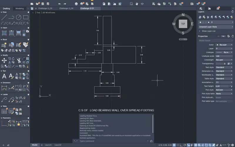
- > C.S Of Load bearing Wall on a Spread Footing. :
1. Create a new page from the application Menu.
2. Choose acad.dwt template from the drop down menu for imperial and decimal values.
3. Use the command type l for invoking line tool.
4. Type Starting Cordinate (0,0).
5. Using relative cordinate methode type (@1.15,0) for the second point.
6. Repeat the above step for the cordinate (@0,0.15); (@0.30,0); 4x times from the starting point (0,0).
7. Now after step 6 type Cordinate (@0,0.15) and followed by (@0,0.05) ; (@0,1); (@0.30); (@0,-1) ; (@0,-0.05) ; (@0,-0.60).
8. Now on clicking the last cordinate make a line to (0.30,0.15) in negative x direction.
9. Repeat the above step 8 to create a line from (1.20,0.60) and (0.120,0.15).
10. Using reactangle command create a rectangle with Length : 1.15 and Bredth : 0.60.
11. Now using line command create a line from Starting point (1.20,0.15) and (@0,-0.40) as second point.
12. Repeat the line tool by points (@-0.05,0); (@0,-0.40); (@-0.20,0); (@0,-0.25); (@0.90,0); (@0,0.25); (@-0.20,0); (@0,0.40); (@-0.05,0); (@0,0.40).
13. Now press the esc to exit the line tool.
14. Using offset tool create a parallel line above the bottom step by 0.25 space and also above rectangle by 0.05.
RESULT :-
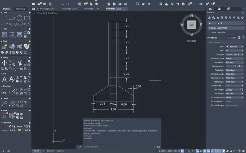
-> C.S Isolated Footing
1. Create a new page from the application Menu.
2. Choose acad.dwt template from the drop down menu for imperial and decimal values.
3. Use the command type l for invoking line tool.
4. Type Starting Cordinate (0,0).
5. Using relative cordinate methode type (@1,0) for the second point.
6. Following by (@0,0.15); (@-0.38,0.25); (@0,1.60); (@-0.24,0); (@0,-1.60); (@-0.38,-0.25); and type c to close the geometry.
7. Press Esc key to exit the line tool.
8. Now type offset to invoke offset tool and make a offset from the bottom with a space of 0.04.
9. Same to above column of space 0.04 on both sides in vertical direction.
10. Repeat for horizontal direction from the top side of space 0.20 for 9 x times.
12. Using trim tool to erase the in between unwanted lines.
13. Press Esc key to exit the offset tool.
RESULT :-
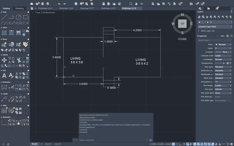
-> Line Diagram for two bedroom building
1.1. Create a new page from the application Menu.
2. Choose acad.dwt template
3. Using Rect command create rectangle with Length: 8.80 and Width : 3.60 from cordinate (0,0).
4. Now exit the rectangle tool by pressing esc key.
5. Using the line tool put the starting point as (3.60,0). Put the next point by relative cordinate system (@0,0.90).
6. Again from starting point put (@0,-0.90); (@1,0) and (@0,0.90).
7. By offset tool make Step by providing space 0.30 make 3 step.
8. Repeat above step 7 with starting point as (3.6, 3.6) and second point (@0,-1.80) and rest same for 3 steps.
9. Trim the last line of the 3rd step in both directions.
10. Now by using the text tool write the text "LIVING 3.6X4.2 " on right side and " LIVING 3.6X3.6" on left side.
RESULT :-
-> C.S of Load Bearing Wall Showing foundation details
1. Create a new page from the application Menu.
2. Choose acad.dwt template
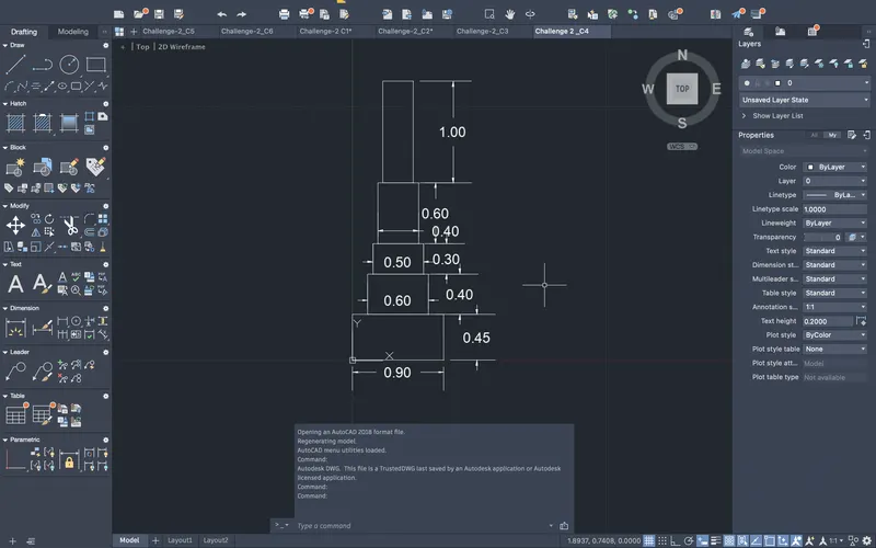
3. Using reactangle tool create reactangle from origin (0,0). Length : 0.90 and Breadth 0.45.
4. Again starting point (0.15,0.45) and next point (0.60,0.40).
5. Again starting point (0.20,0.85) and next point (0.50,0.30).
6. Again starting point (0.25,1.15) and next point (0.40,0.60).
7. Again starting point (0.30,1.75) and next point (0.30,1.0).
8. Exit the rectangle tool by esc Key.
9. Now using trim tool trim 2 and 3 horizontal line from bottom.
10. Press Esc key to exit the trim tool.
RESULT :-
-> Isometric View Of Steps
1. Create a new page from the application Menu.
2. Choose acad.dwt template from the drop down menu for imperial and decimal values.
3. Go to Draft Setting by typing ds in command line. And turn off snap and grid.
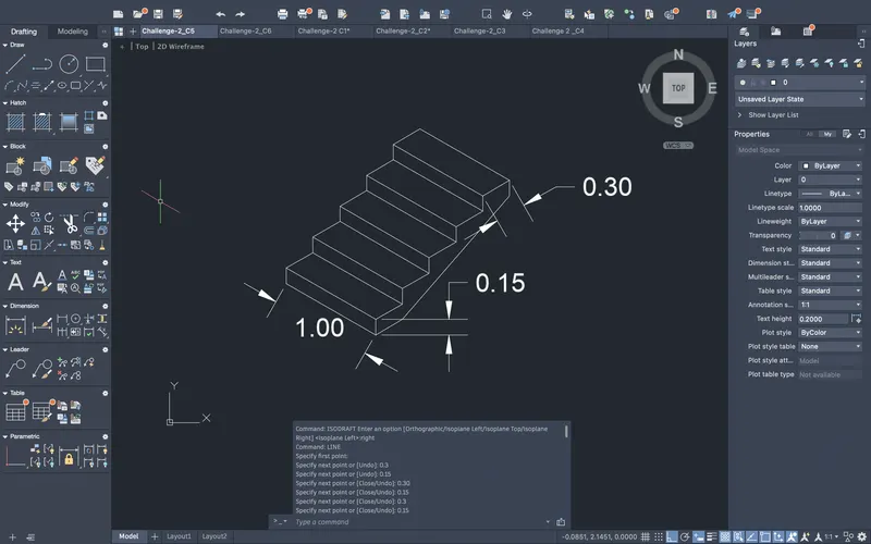
4. Turn on Isoplane left by typing IsoDraft in command.
5. Now by using distance method put 1 as the first line.
6. Now turn on Isoplane right .
7. Put horizontal line distance 0.30 and vertical 0.15. Repeat this to create 5 steps or 5 tread and 5 riser.
8. Make horizontal line of 0.30 in the bottom and 0.15 in the top.
9. Make a line intersection from the end point as the waist slab for stairs.
10. Now again turn on Isoplane left and make horizontal line of 1 unit from vertices of riser.
11. Exit the line tool by pressing esc key.
RESULT :-
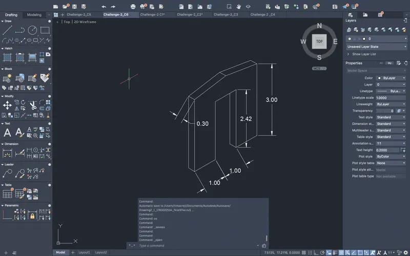
-> Isometric View Of Gable Wall
1. Create a new page from the application Menu.
2. Choose acad.dwt template from the drop down menu for imperial and decimal values.
3. Go to Draft Setting by typing ds in command line. And turn off snap and grid.
4. Turn on Isoplane right by typing IsoDraft in command.
5. Now using line tool and Distance method.
6. Type distance 3 as the vertical line followed by 1 unit, then vertical line 2.42.
7. Followed by 1 in horizontal, 2.42 in vertical, 1 in horizontal, 3 in vertical.
8. Now create a intersection line at the bottom.
9. Now enable mid point at OSNAP.
10. Using the mid point of the intersection line drawn in bottom. Make a line of 3.25 Unit vertical and 0.3 in horizontal.
11. Now using offset tool make offset of first 3 unit exterior wall line and right side inner wall line of 2.42. Also make 0.3 wall thickness at both the wall.
12. Now using move tool adjust the offset line.
13. Now again use offset tool to make roof of 0.3 and repeat the move tool adjustment.
14. Using Esc key exit the tools.
RESULT :-