Sketch a G+1 residential plan according to Vaastu Shastra and Calculation of Loads as per IS code
Aim: Aim of the following project two-fold
- Sketch a G+1 floor residential plan, according to Vaastu Shastra
- Calculate the individual corresponding loads from the members as per IS code for the above sketched G+1 floor residential plan by assuming the appropriate size of members
Introduction:
Vaastu Shastra: Vaastu Shastra lays down the principles of design, layout, measurements, ground preparation, space arrangement and spatial geometry for a home or any built-up structure; sometimes incorporating traditional Hindu (and even Buddhist) religious beliefs, the theories of Vaastu provide ideas and concepts for making a living space harmonious with nature. Vaastu Shastra considers a house to be a living soul and aims at balancing the five elements (earth, fire, water, space, and air) to reach the maximum level of positive energy. Each home or living space comes with its own energy and for a house to be harmonious and happy, it needs to radiate the right kind of energy. At the end of the day, it is the home’s energy that will influence each living members’ mental health. Vaastu Shastra is not restricted to rigid layout diagrams but are much more flexible.
Load Calculation: Load is the primary user of any structure which generates the stress in the building components. Various loads such as live load, dead load, wind load, seismic load, snow load, settlement load, erection load, etc. Structural member also has their own weight as no material is weightless which is called dead load. Dead load is the load that acts on any structure all the time irrespective of any situation. The size and shape of any structural member are always depending on the load (ultimately stress) acting on any member. For keeping economy, time and workmanship of any structural element within control, the load calculation is essentially important especially dead load calculation. For calculation of dead load, size and shape, material and dimensions of the structural member must be known.
SKETCH A G+1 FLOOR RESIDENTIAL PLAN, ACCORDING TO VAASTU SHASTRA
Following are the directions of the building components as per the drawing shown below
main gate = North
Meditation room = East to North East
Living Room = North
Bed Room = South West
Bathroom = North West
Parking = North West
Kitchen = South East
Store Room = South East
GenSat Room/Heavy item room = South West
Staircase = South
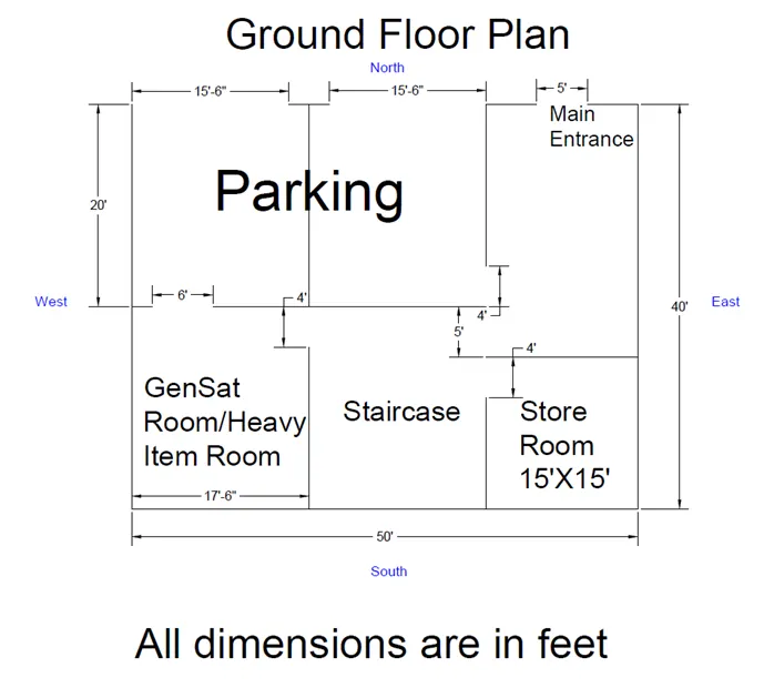
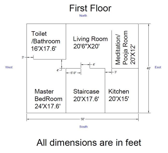
Important drawing for a project
- Centreline drawing
- Depth and soil strata of foundation details
- Footing and column layout with reinforcement details
- Elevation of building
- Column schedule with reinforcement details
- Plinth beam layout with reinforcement details
- Each floor beam layout with reinforcement details
- Each floor slab layout with reinforcement details
- Lift pit and headroom reinforcement details
- Staircase reinforcement and dimension details
CALCULATION OF LOAD OF THE BUILDING:
Calculation of dead load of the building:
A dead load of a building is an inherent property of the structure and it acts during the entire service life. So, calculation of dead load becomes inherent. For calculation of the dead load of the building sketched above I have assumed dimensions of the building component as follow:
Floor Height = 12 feet = 3.66 mtrs
Plinth level (Above ground level) = 0.4 mtrs
Total ht of building from ground level = 0.4 + 3.66 + 3.66 = 7.72 mtrs
Dimension of the beams = 300 mm X 400 mm
Dimension of the columns = 450 mm X 450 mm
Depth of foundation below plinth level = 2 Mtrs (Assuming isolated footing)
The thickness of the slab = 125 mm
The thickness of the wall (Outside walls) = 200 mm
Standard Size of brick = 190x90x90 mm
% of reinforcement in beam = 2% of gross area
% of reinforcement in column = 2 % of gross area
% of main reinforcement in the slab (Along with both directions) = 0.4 % of gross area
The column layout plan of the building is as follow:
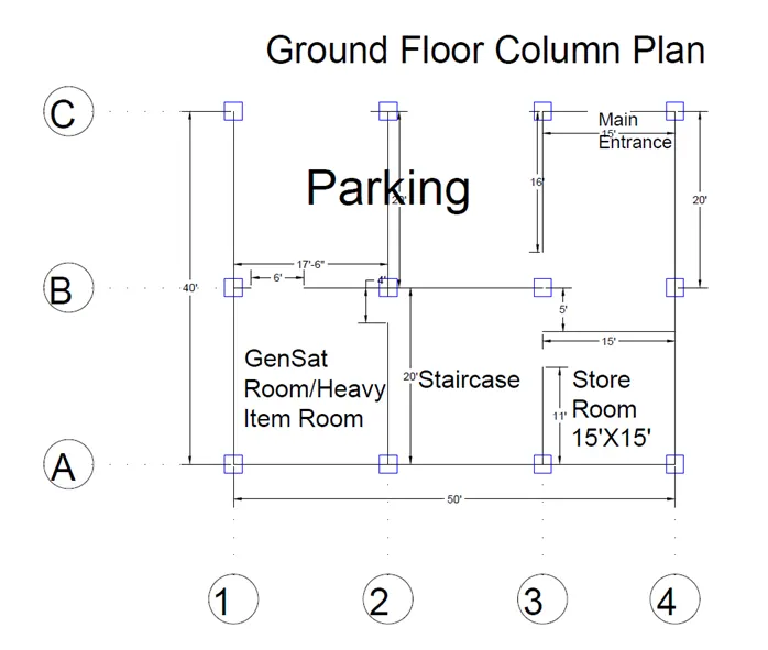
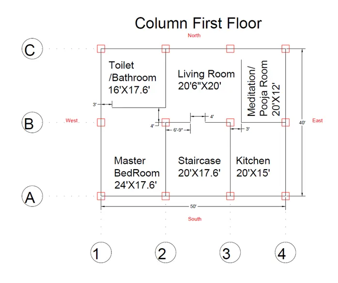
The beam is provided connecting all the columns at the plinth level and first-floor level. Secondary beams are provided on the first floor below the wall which is directly not falling on the beam connecting beams.
Calculation for columns
Number of Column = 12
Area of single column = 0.45*0.45 = 0.2025 m^2
Total Length of column = 2 (Below Plinth Level) + 3.66 + 3.66 = 9.72 mtrs
Area of R/F = 2 % of 0.2025 m^2 = 0.02*0.2025 = 0.00405 m^2
Area of concrete = 0.2025-0.00405 = 0.19845 m^2
Wt of single column = (Area of concrete * Density of concrete + Area of R/F * Density of R/F) * Length of each column
= (0.19845 * 2500 + 0.00405 * 7850) * 9.72
= 5131.358 Kgs = 5.131 MT
Wt of all columns = Wt of each column * number of columns
= 5.131 * 12
Wt of all columns = 61.572 MT = 603.82 KN
Calculation for beams
Number of beams along the shorter direction on all levels (Plinth, Ground Floor and first floor) = 24
Size of each beam = 0.3 X 0.4 = 0.12 m^2
Length of beams along shorter direction = 6.096 mtrs – 0.45 = 5.646 mtrs (reduction is for column size)
Area of R/F = 2 % of gross area
= 0.02 * 0.12
= 0.0024 m^2
Area of Concrete = 0.12 – 0.0024 = 0.1176 m^2
Wt of beams along the shorter direction = Length of beam along shorter dimension * (Area of concrete * 2500 + Area of R/F * 7850)
= 5.646 * (0.1176 * 2500 + 0.0024 * 7850)
= 1766.295 Kgs = 1.767 MT = 17.334 KN
UDL due to dead load on beam along shorter direction = 17.334/5.646 = 3.07 KN/m
Total wt of beam along the shorter direction on both floors = Number of similar beams * wt of each beam
= 24 * 1.767
= 42.408 MT = 416.023 KN
Number of beams along the longer direction on all levels (Plinth, Ground Floor and first floor) = 27
Size of each beam = 0.3 X 0.4 = 0.12 m^2
Length of beams along shorter direction = 5.334 mtrs – 0.45 = 4.884 mtrs (reduction is for column size)
Area of R/F = 2 % of gross area
= 0.02 * 0.12
= 0.0024 m^2
Area of Concrete = 0.12 – 0.0024 = 0.1176 m^2
Wt of beams along the shorter direction = Length of beam along shorter dimension * (Area of concrete * 2500 + Area of R/F * 7850)
= 4.884 * (0.1176 * 2500 + 0.0024 * 7850)
= 1527.911 Kgs = 1.528 MT = 14.989 MT
UDL due to dead load on beam along longer direction = 14.989/4.884 = 3.07 KN/m
Total wt of beam along the longer direction on both floors = Number of similar beams * wt of each beam
=27 * 1.528
= 41.256 MT = 404.721 KN
UDL on beam due to dead load = 3.07 KN/m
Calculation for slabs
The thickness of the slab = 125 mm
All floors slab dimensions = 50’ X 40’ = 15.24 X 12.19 metres
As all the slabs are having a larger dimension less than 2 times the shorter dimension, so all will be designed as two-way slabs.
Generally, slab R/F is found out using 1 metres width strip of slab
Cross section along the shorter dimension = Unit length along larger dimension * thickness
= 1 * 0.125
= 0.125 m^2
Cross section of Reinforcement = 0.4 % of gross area
= 0.004*0.125 = 0.0005 m^2
Cross section of concrete = 0.125 – 0.0005 = 0.1245 m^2
Weight of unit length of slab = 12.19 * (0.1245 * 2500 + 0.0005*7850)
= 3841.983 Kgs = 37.689 MT
Total weight of the slab = larger dimension * 37.689
= 574.3804 MT
Deduction for the staircase area = Area of slab over staircase along unit length
= 1 * 0.125
= 0.125 M^2
R/F area in the staircase slab = 0.004*0.125
= 0.0005 m^2
Area of concrete = 0.125 – 0.0005
= 0.1245 m^2
Unit width wt of staircase slab = 5.334 * (0.0005*7850+0.1245*2500) = 1681.143 Kgs = 16.492 MT
Total weight of staircase slab = 6.096 * 16.492
= 100.535 MT
Net Weight of slab = Total Weight – Deduction for staircase slab
= 574.3804 – 100.535
= 473.845 MT
Net area of slab = Total area – area of staircase
= 15.24 * 12.19 – 6.096 * 5.334
= 153.2595 M^2
UDL of slab = Net weight / Net Area
= 473.845/153.2595
= 3.09 KN/m^2
This UDL will be same on the first floor also.
Calculation for Walls
All walls are non-load bearing walls
For wall calculation, we have assumed windows and doors in rooms. For wall calculation, we have to reduce the weight of window and door openings
Height of each door = 7’ = 2.134 mtrs
Width of each door = as shown in plan above
Size of windows = 5’ X 4’ = 1.524 X 1.219 mtrs
The number of windows and gates in each room as follows
|
Room Type |
Nos of doors and size (Mtrs) |
Number of Windows |
|
Parking |
2, 4.724 |
2 |
|
Store Room |
1, 1.219 |
1 |
|
Staircase |
1, 1.524 |
2 |
|
GenSat Room |
1, 1.829 & 1, 1.219 |
2 |
|
Main Entrance |
1, 1.524 |
1 |
|
Master Bedroom |
1, 1.219 |
3 |
|
Toilet |
1, 0.914 |
0 |
|
Living Room |
1, 1.219 |
2 |
|
Pooja Room |
1, 0.914 |
2 |
|
Kitchen |
1, 0.914 |
3 |
|
Total |
|
18 |
Total area for windows = Number of windows * size of window
= 18 * 1.524 * 1.219
= 33.44 m^2
The total area of doors = Number of doors * size of doors
For Parking Doors = 2 * 4.424 * 2.134
= 18.882 m^2
For Doors of 6’ = 1 * 1.829 * 2.134
= 3.903 m^2
For Doors of 5’ = 2 * 1.524 * 2.134
= 6.504 m^2
For Doors of 4’ = 4 * 1.219 * 2.134
= 10.405 m^2
For Doors of 3’ = 3 * 0.914 * 2.134
= 5.851 m^2
Total area of doors = sum of all doors
= 18.882+6.504+10.405+5.851+3.903
= 45.545 m^2
Net Height of walls (Ceiling Height) = Floor height – Depth of beam – slab thickness
= 3.66 – 0.4 – 0.125
= 3.315 metres
Area of wall = sum of the length of all walls * Width of wall
Sum of length of all walls = sum on ground floor + sum on first floor
= (4*40+3*50) + (4*40 + 3*50)
= 620’ = 188.976 metres
Total area of walls = 188.976 * 3.315
= 626.455 m^2
Net area of walls =Total area – Area of doors – Area of windows
= 626.455 – 45.545 – 33.44
Net wall surface area = 547.47 m^2
The thickness of walls = 0.2 metres
Volume of walls = Net wall surface area * Thickness of walls
= 547.47 * 0.2
= 109.494 m^3
Taking the Unit weight of brick masonry = 1920 kg/m^3
Total weight of brick masonry = 109.494 * 1920
= 210.228 MT = 2062.341 KN
UDL on beam due to walls (Approx) = Total weight of walls / Total length of walls
= 2062.341/ 188.976
= 10.91 KN/m
(Here I have taken the total running length of the wall on one floor for approximate calculation, First Floor wall generates the same UDL on beams)
Calculation of live load of the building:
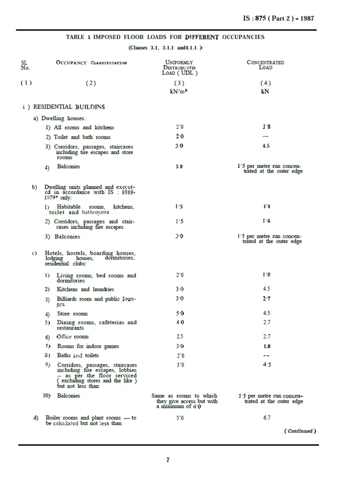
For live load calculation, I shall refer to the IS 875 (Part 2): 1987
As per table - 1 of the above-mentioned code, the following load on floors shall be taken for different parts of the buildings
For Kitchen = 2 kn/m^2 (UDL) and 1.8 KN (Concentrated Load)
For Living Room = 2 kn/m^2 (UDL) and 1.8 KN (Concentrated Load)
For Bedroom = 2 kn/m^2 (UDL) and 1.8 KN (Concentrated Load)
For Toilet = 2 kn/m^2 (UDL)
For Pooja Room = 2 kn/m^2 (UDL) and 1.8 KN (Concentrated Load)
Staircase = 3 kn/m^2 (UDL) and 4.5 KN (Concentrated Load)
Roof Load(Access Provided) = 1.5 kn/m^2 (UDL)
Calculation of Wind load of the building:
As per IS 875 (Part-3): 1987, wind load calculation for the building having a total height of fewer than 10 meters from ground level can be neglected.
Results:
A G+1 residential building plan as per Vaastu Shastra has been shown above with all the dimensions of the beams, columns, walls, doors and windows. Building components are placed as per the Vaastu as follow
The direction of the main gate = North
Meditation room = East to North East
Living Room = North
Bed Room = South West
Bathroom = North West
Parking = North West
Kitchen = South East
Store Room = South East
GenSat Room/Heavy item room = South West
Staircase = South
For the G+1 residential building load due to dead load, live load and wind load has been calculated and summarized as below:
For Column
Dead Load = 50.335 KN (For Single Column) and 603.82 KN (For all columns)
Live Load = 0 KN/m
Wind Load = 0 KN/m
For Beam
Dead Load = 3.07 KN/m (Beam Self Load) + 10.91 KN/m (Due to walls) = 13.98 KN/m
Live Load = 0 KN/m
Wind Load = 0 KN/m
For Slabs
Dead Load = 3.09 KN/m^2
Live Load
For Kitchen = 2 kn/m^2 (UDL) and 1.8 KN (Concentrated Load)
For Living Room = 2 kn/m^2 (UDL) and 1.8 KN (Concentrated Load)
For Bedroom = 2 kn/m^2 (UDL) and 1.8 KN (Concentrated Load)
For Toilet = 2 kn/m^2 (UDL)
For Pooja Room = 2 kn/m^2 (UDL) and 1.8 KN (Concentrated Load)
Staircase = 3 kn/m^2 (UDL) and 4.5 KN (Concentrated Load)
Roof Load (Access Provided) = 1.5 kn/m^2 (UDL)
Wind Load = 0 KN/m^2
The above-calculated load will be used for the design of the building with the load combination as provided by table 18 of IS 1893:2002