Creating a Floor plan, Footing detail and Isometric view using AutoCad
Cross Section of Load Bearing Wall over Spread Footing:
Aim:
Drawing of Cross Section Load Bearing Wall
Procedure:
Drawing of the first rectangle of 0.9x0.25
- Command: REC
- RECTANG
- Specify first corner point or [Chamfer/Elevation/Fillet/Thickness/Width]: 0,0
- Specify other corner point or [Area/Dimensions/Rotation]: d
- Specify length for rectangles <10.0000>: 0.9
- Specify width for rectangles <10.0000>: 0.25
- Specify other corner point or [Area/Dimensions/Rotation]:
Drawing of 1st and 2nd pedestal of 0.4 ht each just above rectangle drawn above
- Command: L
- LINE
- Specify first point: 0.2,0.25
- Specify next point or [Undo]: @0,0.4
- Specify next point or [Undo]: @0.05,0
- Specify next point or [Close/Undo]: @0,0.4
- Specify next point or [Undo]: @0.4,0
- Specify next point or [Undo]: @0,-0.4
- Specify next point or [Close/Undo]: @0.05,0
- Specify next point or [Close/Undo]: @0,-0.4
- Specify next point or [Close/Undo]: c
Drawing of Rectangle of 1.15x0.15 on the left side of wall
- Command: REC
- RECTANG
- Specify first corner point or [Chamfer/Elevation/Fillet/Thickness/Width]: 0.25,1.05
- Specify other corner point or [Area/Dimensions/Rotation]: d
- Specify length for rectangles <1.1500>: 1.15
- Specify width for rectangles <0.1500>: 0.15
- Specify other corner point or [Area/Dimensions/Rotation]:
Drawing wall of 1.65x0.3 above pedestal of 0.4 width
- Command: L
- LINE
- Specify first point: 0.3,1.05
- Specify next point or [Undo]: @0,1.65
- Specify next point or [Undo]: @0.3,0
- Specify next point or [Close/Undo]: @0,-1.65
- Specify next point or [Close/Undo]: c
Drawing of steps with riser of 0.15 above rectangular slab of 1.15x0.15
- Command: L
- LINE
- Specify first point: 0.3,1.05
- Specify next point or [Undo]: @-0.9,0
- Specify next point or [Undo]: @0,0.15
- Specify next point or [Close/Undo]: @0.3,0
- Specify next point or [Close/Undo]: @0,0.15
- Specify next point or [Close/Undo]: @0.3,0
- Specify next point or [Close/Undo]: @0,0.15
- Specify next point or [Close/Undo]: @0.3,0
- Specify next point or [Close/Undo]:
Drawing of rectangle of size 1x0.6 on right of wall
- Command: REC
- RECTANG
- Specify first corner point or [Chamfer/Elevation/Fillet/Thickness/Width]: 0.6,1.05
- Specify other corner point or [Area/Dimensions/Rotation]: d
- Specify length for rectangles <1.1500>: 1
- Specify width for rectangles <0.1500>: 0.6
- Specify other corner point or [Area/Dimensions/Rotation]:
Drawing of 2 lines in 0.3 width portion
- Command: L
- LINE
- Specify first point: 0.6,1.65
- Specify next point or [Undo]: @-0.3,0
- Specify next point or [Undo]:
- Command: OFFSET
- Current settings: Erase source=No Layer=Source OFFSETGAPTYPE=0
- Specify offset distance or [Through/Erase/Layer] <1.0000>: 0.05
- Select object to offset or [Exit/Undo] <Exit>:
- Specify point on side to offset or [Exit/Multiple/Undo] <Exit>:
- Select object to offset or [Exit/Undo] <Exit>: e
Result:
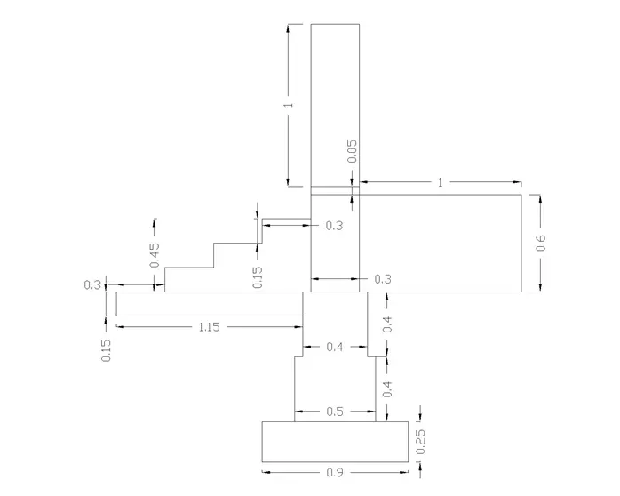
Cross Section of Load Bearing wall Over Spread Footing
Cross Section of Isolated Footing
Aim:
Drawing of Cross Section of Isolated Footings
Procedure:
Drawing of Outer walls of Footings
- Command: L
- LINE
- Specify first point: 0,0
- Specify next point or [Undo]: @1,0
- Specify next point or [Undo]: @0,0.15
- Specify next point or [Close/Undo]: @-0.38,0.25
- Specify next point or [Close/Undo]: @0,1.6
- Specify next point or [Close/Undo]: @-0.24,0
- Specify next point or [Close/Undo]: @0,-1.6
- Specify next point or [Close/Undo]: @-0.38,-0.25
- Specify next point or [Close/Undo]: @0,-0.15
- Specify next point or [Close/Undo]:
Drawing of Reinforcement of Isolated Footing
- Command: L
- LINE
- Specify first point: 0.42,0.2
- Specify next point or [Undo]: @0.16,0
- Specify next point or [Undo]:
- Command: OFFSET
- Current settings: Erase source=No Layer=Source OFFSETGAPTYPE=0
- Specify offset distance or [Through/Erase/Layer] <0.0500>: 0.2
- Select object to offset or [Exit/Undo] <Exit>:
- Specify point on side to offset or [Exit/Multiple/Undo] <Exit>: m
- Specify point on side to offset or [Exit/Undo] <next object>:
- Specify point on side to offset or [Exit/Undo] <next object>:
- Specify point on side to offset or [Exit/Undo] <next object>:
- Specify point on side to offset or [Exit/Undo] <next object>:
- Specify point on side to offset or [Exit/Undo] <next object>:
- Specify point on side to offset or [Exit/Undo] <next object>:
- Specify point on side to offset or [Exit/Undo] <next object>:
- Specify point on side to offset or [Exit/Undo] <next object>:
- Specify point on side to offset or [Exit/Undo] <next object>:
- Select object to offset or [Exit/Undo] <Exit>: e
Marking of Dimensions of Drawing
- Command: DIMLIN
- DIMLINEAR
- Specify first extension line origin or <select object>:
- Specify second extension line origin:
- Specify dimension line location or
- [Mtext/Text/Angle/Horizontal/Vertical/Rotated]:
- Dimension text = 1.6
- Command:
- DIMLINEAR
- Specify first extension line origin or <select object>:
- Specify second extension line origin:
- Specify dimension line location or
- [Mtext/Text/Angle/Horizontal/Vertical/Rotated]:
- Dimension text = 0.24
- Command:
- DIMLINEAR
- Specify first extension line origin or <select object>:
- Specify second extension line origin:
- Specify dimension line location or
- [Mtext/Text/Angle/Horizontal/Vertical/Rotated]:
- Dimension text = 0.16
- Command:
- DIMLINEAR
- Specify first extension line origin or <select object>:
- Specify second extension line origin:
- Specify dimension line location or
- [Mtext/Text/Angle/Horizontal/Vertical/Rotated]:
- Dimension text = 1
- Command: DIMLIN
- DIMLINEAR
- Specify first extension line origin or <select object>:
- Specify second extension line origin:
- Specify dimension line location or
- [Mtext/Text/Angle/Horizontal/Vertical/Rotated]:
- Dimension text = 0.15
- Command:
- DIMLINEAR
- Specify first extension line origin or <select object>:
- Specify second extension line origin:
- Specify dimension line location or
- [Mtext/Text/Angle/Horizontal/Vertical/Rotated]:
- Dimension text = 0.38
- Command:
- DIMLINEAR
- Specify first extension line origin or <select object>:
- Specify second extension line origin:
- Specify dimension line location or
- [Mtext/Text/Angle/Horizontal/Vertical/Rotated]:
- Dimension text = 0.16
- Command:
- DIMLINEAR
- Specify first extension line origin or <select object>:
- Specify second extension line origin:
- Specify dimension line location or
- [Mtext/Text/Angle/Horizontal/Vertical/Rotated]:
- Dimension text = 0.2
- Command:
- DIMLINEAR
- Specify first extension line origin or <select object>:
- Specify second extension line origin:
- Specify dimension line location or
- [Mtext/Text/Angle/Horizontal/Vertical/Rotated]:
- Dimension text = 0.04
- Command:
- DIMLINEAR
- Specify first extension line origin or <select object>:
- Specify second extension line origin:
- Specify dimension line location or
- [Mtext/Text/Angle/Horizontal/Vertical/Rotated]:
- Dimension text = 0.05
- Command:
- DIMLINEAR
- Specify first extension line origin or <select object>:
- Specify second extension line origin:
- Specify dimension line location or
- [Mtext/Text/Angle/Horizontal/Vertical/Rotated]:
- Dimension text = 0.38
Result:
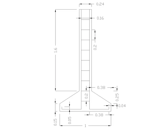
Drawing of Isolated Footing with Reinforcement
Line Diagram of Two Bedrooms Building
Aim:
Drawing of a line diagram of two bedrooms building
Procedure:
Drawing of Bedroom
- Command: L
- LINE
- Specify first point: 0,0
- Specify next point or [Undo]: @3.6,0
- Specify next point or [Undo]: @0,0.9
- Specify next point or [Close/Undo]:
- Command: L
- LINE
- Specify first point: 0,0
- Specify next point or [Undo]: @0,3.6
- Specify next point or [Undo]: @3.6,0
- Specify next point or [Close/Undo]: @0,-1.8
- Specify next point or [Close/Undo]:
Drawing of stairs on both sides of living room
- Command: L
- LINE
- Specify first point: 3.6,0
- Specify next point or [Undo]: @0,-0.9
- Specify next point or [Undo]: @1,0
- Specify next point or [Close/Undo]: @0,0.9
- Specify next point or [Close/Undo]: @0,-0.3
- Specify next point or [Close/Undo]: @-1,0
- Specify next point or [Close/Undo]:
- Command: CO
- COPY
- Select objects: 1 found
- Select objects:
- Current settings: Copy mode = Multiple
- Specify base point or [Displacement/mOde] <Displacement>: 4.6,-0.3
- Specify second point or [Array] <use first point as displacement>: -0.3
- Specify second point or [Array/Exit/Undo] <Exit>: e
As Stairs are symmetrical about the bedroom
- Command: _mirror
- Select objects: *Cancel*
- Command: MIRROR
- Select objects: Specify opposite corner: 6 found
- Select objects:
- Specify first point of mirror line: 3.6,1.8
- Specify second point of mirror line: <Ortho on>
- Erase source objects? [Yes/No] <No>: n
Drawing of Living Room
- Command: <Ortho off>
- Command: L
- LINE
- Specify first point: 4.6,0
- Specify next point or [Undo]: @4.2,0
- Specify next point or [Undo]: @0,3.6
- Specify next point or [Close/Undo]: @-4.2,0
- Specify next point or [Close/Undo]:
Marking of Dimensions in the drawings
- Command: DIMLIN
- DIMLINEAR
- Specify first extension line origin or <select object>:
- Specify second extension line origin:
- Non-associative dimension created.
- Specify dimension line location or
- Dimension text = 0.9
- Command:
- DIMLINEAR
- Specify first extension line origin or <select object>:
- Specify second extension line origin:
- Specify dimension line location or
- Dimension text = 0.3
- Command:
- DIMLINEAR
- Specify first extension line origin or <select object>:
- Specify second extension line origin:
- Specify dimension line location or
- Dimension text = 0.3
- Command:
- DIMLINEAR
- Specify first extension line origin or <select object>:
- Specify second extension line origin:
- Specify dimension line location or
- Dimension text = 0.3
- Command:
- DIMLINEAR
- Specify first extension line origin or <select object>:
- Specify second extension line origin:
- Specify dimension line location or
- Dimension text = 1
- Command:
- DIMLINEAR
- Specify first extension line origin or <select object>:
- Specify second extension line origin:
- Specify dimension line location or
- Dimension text = 1.8
- Command:
- DIMLINEAR
- Specify first extension line origin or <select object>:
- Specify second extension line origin:
- Specify dimension line location or
- Dimension text = 0.9
Adding Texts
- Command: TEXT
- Current text style: "Standard" Text height: 5000 Annotative: No Justify: Left
- Specify start point of text or [Justify/Style]:
- Specify height <2.5000>: 0.25
- Specify rotation angle of text <0>: 0
Result:
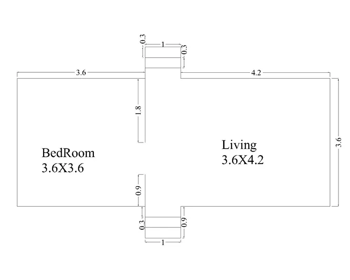
Line Diagram of Two-Bedroom Building
Cross Section of Load Bearing Wall Showing Foundation Details
Aim:
Drawing of a Cross-Section of Load Bearing Wall Showing Foundation Details
Procedure:
Drawing of Base Pedestal of Size 0.9x0.45
- Command: REC
- RECTANG
- Specify first corner point or [Chamfer/Elevation/Fillet/Thickness/Width]: 0,0
- Specify other corner point or [Area/Dimensions/Rotation]: d
- Specify length for rectangles <0.9000>: 0.9
- Specify width for rectangles <0.4500>: 0.45
- Specify other corner point or [Area/Dimensions/Rotation]:
Drawing of 2 Steps pedestal above base rectangle
- Command: L
- LINE
- Specify first point: 0.15,0.45
- Specify next point or [Undo]: @0,0.4
- Specify next point or [Undo]: @0.05,0
- Specify next point or [Close/Undo]: @0,0.3
- Specify next point or [Close/Undo]: @0.05,0
- Specify next point or [Close/Undo]: @0,0.6
- Specify next point or [Close/Undo]: @0.4,0
- Specify next point or [Close/Undo]: @0,-0.6
- Specify next point or [Close/Undo]: @0.05,0
- Specify next point or [Close/Undo]: @0,-0.3
- Specify next point or [Close/Undo]: @0.05,0
- Specify next point or [Close/Undo]: @0,-0.4
- Specify next point or [Close/Undo]:
Drawing of Top Pedestal of size 0.3X1
- Command: REC
- RECTANG
- Specify first corner point or [Chamfer/Elevation/Fillet/Thickness/Width]: 0.3,1.75
- Specify other corner point or [Area/Dimensions/Rotation]: d
- Specify length for rectangles <0.9000>: 0.3
- Specify width for rectangles <0.4500>: 1
- Specify other corner point or [Area/Dimensions/Rotation]:
Result:
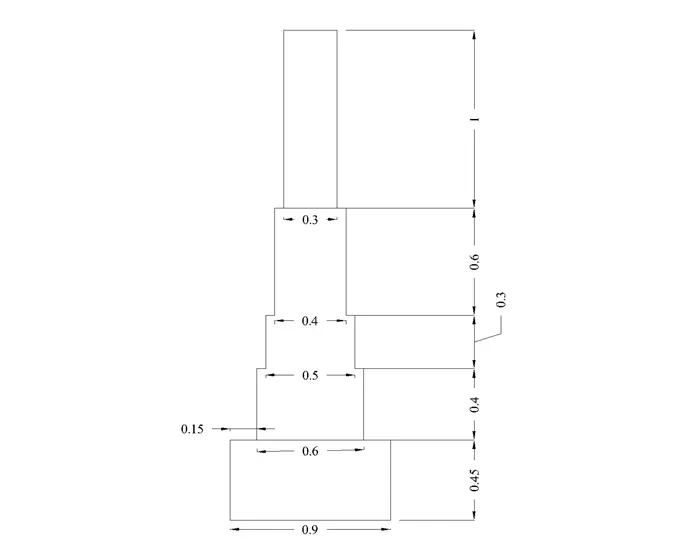
Cross Section of Load Bearing Wall Showing Foundation Details
Isometric View of Steps
Aim:
Drawing of Isometric View of Steps
Procedure:
Drawing of Steps with riser of 0.15
- Command: _.ISODRAFT
- Enter an option [Orthographic/isoplane Left/isoplane Top/isoplane Right] <Orthographic>:_Left
- Command: <Ortho on>
- Command: L
- LINE
- Specify first point: 0,0
- Specify next point or [Undo]: 1
- Specify next point or [Undo]: 0.15
- Specify next point or [Close/Undo]: 1
- Specify next point or [Close/Undo]: 0.15
- Specify next point or [Close/Undo]: c
Drawing of Landing of 0.3 width
- Specify next point or [Undo]: <Ortho off>
- Command: <Isoplane Top>
- Command: L
- LINE
- Specify first point: 0,0.15
- Specify next point or [Undo]: <Ortho on> 0.3
- Specify next point or [Undo]: 1
- Specify next point or [Close/Undo]: 0.3
- Specify next point or [Close/Undo]:
All the riser and landing are similar
- Command: COPY
- Select objects: Specify opposite corner: 9 found
- Select objects:
- Current settings: Copy mode = Multiple
- Specify base point or [Displacement/mOde] <Displacement>: 0,0
- Specify second point or [Array/Exit/Undo] <Exit>:
- Specify second point or [Array/Exit/Undo] <Exit>:
- Specify second point or [Array/Exit/Undo] <Exit>:
- Specify second point or [Array/Exit/Undo] <Exit>:
Drawing of Staircase slab at back of stairs
- Command: L
- LINE
- Specify first point: 0,0
- Specify next point or [Undo]: <Ortho on> 0.3
- Specify next point or [Undo]:
- Command: L
- LINE
- Specify first point: 1.299,1.5
- Specify next point or [Undo]: <Isoplane Left> 0.15
- Specify next point or [Undo]:
- Command: <Ortho off>
- Command: L
- LINE
- Specify first point:
- Specify next point or [Undo]:
- Specify next point or [Undo]:
Marking Dimesons of Stairs
- Command: DIMALI
- DIMALIGNED
- Specify first extension line origin or <select object>:
- Specify second extension line origin:
- Specify dimension line location or
- [Mtext/Text/Angle]:
- Dimension text = 0.3
- Command:
- DIMALIGNED
- Specify first extension line origin or <select object>:
- Specify second extension line origin:
- Specify dimension line location or
- [Mtext/Text/Angle]:
- Dimension text = 1
- Command:
- DIMALIGNED
- Specify first extension line origin or <select object>:
- Specify second extension line origin:
- Specify dimension line location or
- [Mtext/Text/Angle]:
- Dimension text = 0.15
Result:
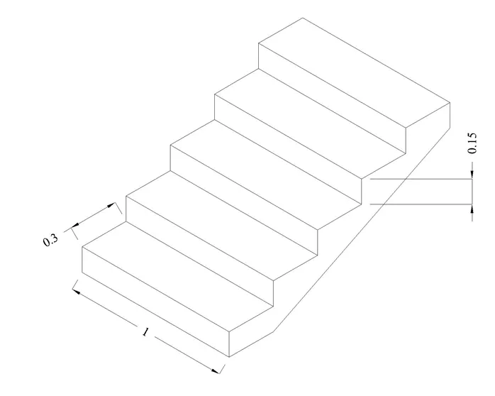
Isometric View of Steps
Isometric View of Gable Wall
Aim:
Drawing of Isometric View of Gable Wall
Procedure:
Drawing from Left side of wall in Isometric View using cursor guide
- Select objects: <Isoplane Right>
- Command: <Ortho on>
- Command: L
- LINE
- Specify first point: 0,0
- Specify next point or [Undo]: 1
- Specify next point or [Undo]: 2.42
- Specify next point or [Close/Undo]: 1
- Specify next point or [Close/Undo]: 2.42
- Specify next point or [Close/Undo]: 1
- Specify next point or [Close/Undo]: 3
- Specify next point or [Close/Undo]:
- Command: L
- LINE
- Specify first point: 0,0
- Specify next point or [Undo]: 3
- Specify next point or [Undo]: <Isoplane Left> 0.3
- Specify next point or [Close/Undo]: 3
- Specify next point or [Close/Undo]: 0.3
- Specify next point or [Close/Undo]:
- Command: <Isoplane Left>
Drawing of Double Line on right side of opening at 0.3 width
- Command: L
- LINE
- Specify first point:
- Specify next point or [Undo]: 0.3
- Specify next point or [Undo]:
- Specify next point or [Close/Undo]:
Drawing of 0.3 widths of the triangular portion
- Command: L
- LINE
- Specify first point:
- Specify next point or [Undo]: 0.3
- Specify next point or [Undo]:
Drawing of Triangular Dimensions with the help of AutoCAD Drawing given in instruction due to insufficient data given in question
- Command: L
- LINE
- Specify first point: 0,3
- Specify next point or [Undo]: @2.18<53
- Specify next point or [Undo]: 2.5984,4.5
- Specify next point or [Close/Undo]:
- Command: COPY
- Select objects: Specify opposite corner: 0 found
- Select objects: Specify opposite corner: 2 found
- Select objects:
- Current settings: Copy mode = Multiple
- Specify base point or [Displacement/mOde] <Displacement>: 0,3
- Specify second point or [Array] <use first point as displacement>: -0.2598,3.15
- Specify second point or [Array/Exit/Undo] <Exit>: e
Result:
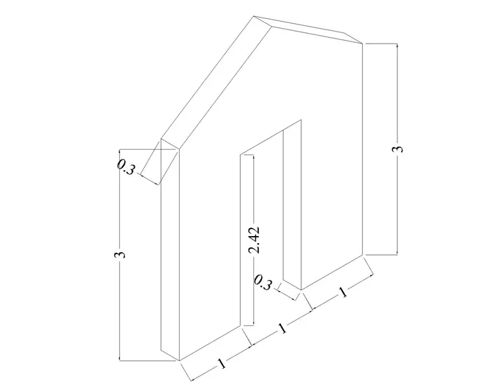
Isometric View of Gable Wall
Conclusion:
Drawing of some practice line diagrams gives a very well-founded practice for various tools of AutoCAD which are very useful in advanced drafting. Upon drawing drawings there is a good practice of various tools like – Line, Copy, Mirror, Move, Rectangle, Ortho, Isometric View, Dimension, etc.