Drafting of various geometries using Chamfer, Fillet tool in AutoCad
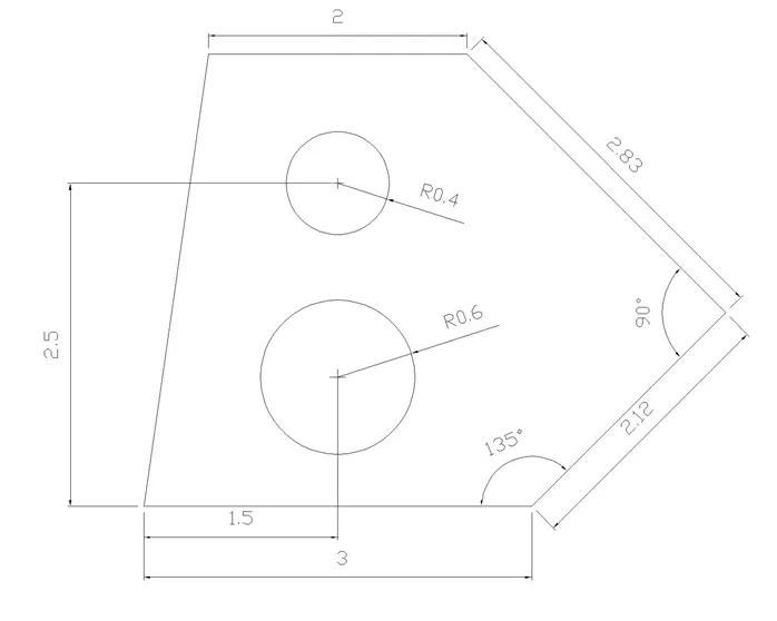
Decimal System of Unit Measurement/ Drawing No 1
Aim: Use of decimal system unit measurement on a drawing
Procedure:
Starting from first point as origin of UCS i.e. (0,0)
- Command: L
- LINE
- Specify first point: 0,0
- Specify next point or [Undo]: @3,0
- Specify next point or [Undo]: @2.12<45
- Specify next point or [Close/Undo]: @2.83<135
- Specify next point or [Close/Undo]: @2<180
- Specify next point or [Close/Undo]: c
Drawing of circles
- Command: CIRCLE
- Specify center point for circle or [3P/2P/Ttr (tan tan radius)]: 1.5,1
- Specify radius of circle or [Diameter] <1.2000>: d
- Specify diameter of circle <2.4000>: 1.2
- Command: CIRCLE
- Specify center point for circle or [3P/2P/Ttr (tan tan radius)]: 1.5,2.5
- Specify radius of circle or [Diameter] <0.6000>: d
- Specify diameter of circle <1.2000>: 0.8
Setting decimal system for measurement
- Home>Annotation>Dimension style
- Click Modify>Choose Primary Unit set decimal amongst dropdowns of unit format
Measuring Dimensions
- Command: DIMALI
- DIMALIGNED
- Specify first extension line origin or <select object>:
- Specify second extension line origin:
- Specify dimension line location or
- Dimension text = 2.83
- Command:
- DIMALIGNED
- Specify first extension line origin or <select object>:
- Specify second extension line origin:
- Non-associative dimension created.
- Specify dimension line location or
- Dimension text = 2
- Command:
- DIMALIGNED
- Specify first extension line origin or <select object>:
- Specify second extension line origin:
- Specify dimension line location or
- Dimension text = 2.12
- Command:
- DIMALIGNED
- Specify first extension line origin or <select object>:
- Specify second extension line origin:
- Non-associative dimension created.
- Specify dimension line location or
- Dimension text = 3
- Command: CENTERMARK
- Select circle or arc to add center mark: circle
- Select circle or arc to add center mark: circle
- Command: DIMLIN
- DIMLINEAR
- Specify first extension line origin or <select object>:
- Specify second extension line origin:
- Specify dimension line location or
- Dimension text = 1.5
- Command: DIMLIN
- DIMLINEAR
- Specify first extension line origin or <select object>:
- Specify second extension line origin:
- Non-associative dimension created.
- Specify dimension line location or
- Dimension text = 2.5
- Command: DIMRAD
- DIMRADIUS
- Select arc or circle:
- Dimension text = 0.6
- Command:
- DIMRADIUS
- Select arc or circle:
- Dimension text = 0.4
- Command: DIMANG
- DIMANGULAR
- Select arc, circle, line, or <specify vertex>:
- Select second line:
- Dimension text = 135
- Command:
- DIMANGULAR
- Select arc, circle, line, or <specify vertex>:
- Select second line:
- Dimension text = 90
Result:
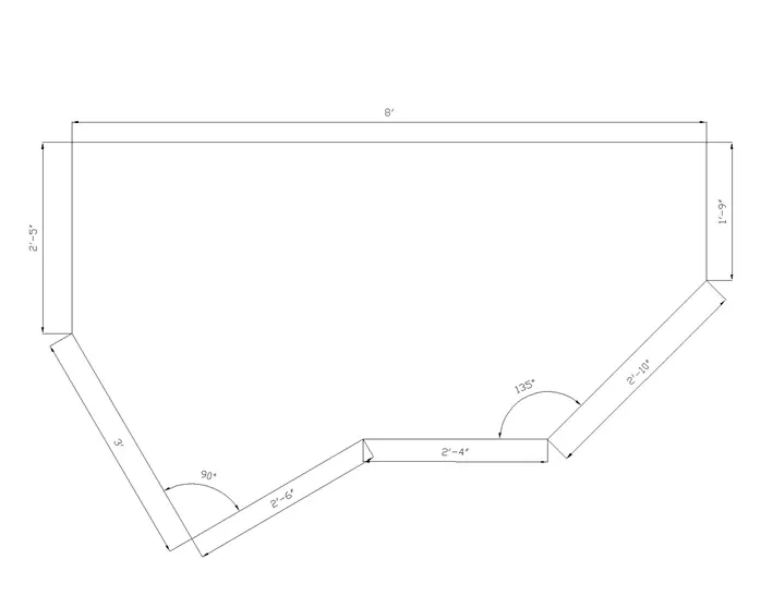
Architectural System of Unit Measurement/ Drawing No 2
Aim: Use of architectural system unit measurement on a drawing
Procedure:
Starting from the first point as the origin of UCS i.e. (0,0)
Setting architectural system for measurement
- Home>Annotation>Dimension style
- Click Modify>Choose Primary Unit set architectural amongst dropdowns of unit format
- Command: UNITS
- Set units as architectural as a unit set to measure as inches
Drawing of diagram
- Command: L
- LINE
- Specify first point: 0,0
- Specify next point or [Undo]: @8',0'
- Specify next point or [Undo]:
- Specify next point or [Undo]: @0,-1'9"
- Specify next point or [Close/Undo]: @2'10"<225
- Specify next point or [Close/Undo]:
- Command: L
- LINE
- Specify first point: 0,0
- Specify next point or [Undo]: @2'5"<270 <Ortho off>
- Specify next point or [Undo]: @3'<300.2296
- Specify next point or [Close/Undo]: @2'6"<30.2296
- Specify next point or [Close/Undo]:
- Specify next point or [Close/Undo]:
Results:
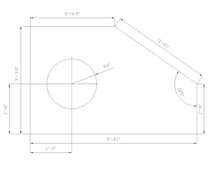
Engineering System of Unit Measurement/Drawing No 3
Aim: Use of engineering unit measurement on a drawing
Procedure:
Starting from the first point as the origin of UCS i.e. (0,0)
Setting engineering system for measurement
- Home>Annotation>Dimension style
- Click Modify>Choose Primary Unit set engineering amongst dropdowns of unit format
- Command: UNITS
- Set units as engineering as unit set to measure as inches
Drawing of sketch
- Command: L
- LINE
- Specify first point: 0,0
- Specify next point or [Undo]: @5'0.1",0
- Specify next point or [Undo]: @0,1'6"
- Specify next point or [Close/Undo]: @3'0.13"<145
- Specify next point or [Close/Undo]: @2'6.5"<180
- Specify next point or [Close/Undo]: c
- Command: CIRCLE
- Specify center point for circle or [3P/2P/Ttr (tan tan radius)]: 1'3",1'6"
- Specify radius of circle or [Diameter] <0'-0">: d
- Specify diameter of circle <0'-1">: 1'6"
Results:
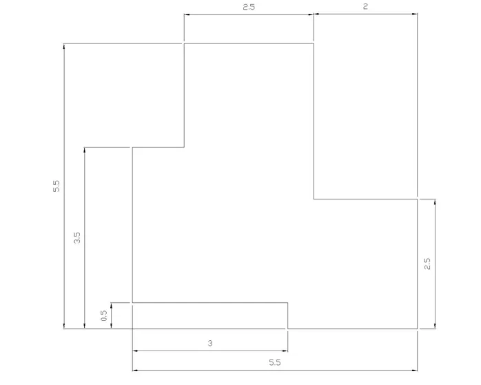
Drawing No 4
Aim: Drawing of Given Drawing using various tools in AutoCAD
Procedure:
Starting from the first point as the origin of UCS i.e. (0,0). All the drawings from now on will be drawn in Decimal System.
Setting engineering system for measurement
- Home>Annotation>Dimension style
- Click Modify>Choose Primary Unit set Decimal amongst dropdowns of unit format
- Command: UNITS
- Set units as Decimal as unit set to measure as millimeter
Drawing
- Command: L
- LINE
- Specify first point: 0,0
- Specify next point or [Undo]: @3,0
- Specify next point or [Undo]: @0,-0.5
- Specify next point or [Close/Undo]: @2.5,0
- Specify next point or [Close/Undo]: @0,2.5
- Specify next point or [Close/Undo]: @-2,0
- Specify next point or [Close/Undo]: @0,3
- Specify next point or [Close/Undo]: @-2.5,0
- Specify next point or [Close/Undo]: @0,-2
- Specify next point or [Close/Undo]: @-1,0
- Specify next point or [Close/Undo]: c
Dimension Measurement:
- Command: DIMLIN
- DIMLINEAR
- Specify first extension line origin or <select object>:
- Specify second extension line origin:
- Specify dimension line location or
- Dimension text = 2.5
- Command:
- DIMLINEAR
- Specify first extension line origin or <select object>:
- Specify second extension line origin:
- Specify dimension line location or
- Dimension text = 2
- DIMLINEAR
- Specify first extension line origin or <select object>:
- Specify second extension line origin:
- Specify dimension line location or
- Dimension text = 2
- Command:
- DIMLINEAR
- Specify first extension line origin or <select object>:
- Specify second extension line origin:
- Specify dimension line location or
- Dimension text = 2.5
- Command: DIMLIN
- DIMLINEAR
- Specify first extension line origin or <select object>:
- Specify second extension line origin:
- Specify dimension line location or
- Dimension text = 5.5
- Command:
- DIMLINEAR
- Specify first extension line origin or <select object>:
- Specify second extension line origin:
- Specify dimension line location or
- Dimension text = 3.5
- Command:
- DIMLINEAR
- Specify first extension line origin or <select object>:
- Specify second extension line origin:
- Specify dimension line location or
- Dimension text = 0.5
- Command:
- DIMLINEAR
- Specify first extension line origin or <select object>:
- Specify second extension line origin:
- Non-associative dimension created.
- Specify dimension line location or
- Dimension text = 3
- Command:
- DIMLINEAR
- Specify first extension line origin or <select object>:
- Specify second extension line origin:
- Non-associative dimension created.
- Specify dimension line location or
- Dimension text = 5.5
Results:
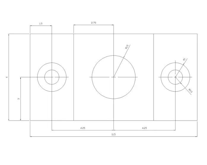
Drawing No 5
Aim: Drawing of Given Drawing using various tools in AutoCAD
Procedure:
Starting from the first point as the origin of UCS i.e. (0,0)
- Command: L
- LINE
- Specify first point: 0,0
- Specify next point or [Undo]: 11.50,0
- Specify next point or [Undo]: @0,6
- Specify next point or [Close/Undo]: @-11.50,0
- Specify next point or [Close/Undo]: c
- Command: L
- LINE
- Specify first point: 3,0
- Specify next point or [Undo]: @0,6
- Specify next point or [Undo]:
- Command: O
- OFFSET
- Current settings: Erase source=No Layer=Source OFFSETGAPTYPE=0
- Specify offset distance or [Through/Erase/Layer] <Through>: 5.5
- Select object to offset or [Exit/Undo] <Exit>:
- Specify point on side to offset or [Exit/Multiple/Undo] <Exit>:
- Select object to offset or [Exit/Undo] <Exit>: e
- Command: CIRCLE
- Specify center point for circle or [3P/2P/Ttr (tan tan radius)]: 1.5,3
- Specify radius of circle or [Diameter]: d
- Specify diameter of circle: 2
- Command:
- CIRCLE
- Specify center point for circle or [3P/2P/Ttr (tan tan radius)]: 1.5,3
- Specify radius of circle or [Diameter] <1>: d
- Specify diameter of circle <2>: 1
- Command: C
- CIRCLE
- Specify center point for circle or [3P/2P/Ttr (tan tan radius)]: 10,3
- Specify radius of circle or [Diameter] <1>: d
- Specify diameter of circle <1>: 2
- Command:
- CIRCLE
- Specify center point for circle or [3P/2P/Ttr (tan tan radius)]: 10,3
- Specify radius of circle or [Diameter] <1>: d
- Specify diameter of circle <2>: 1
- Command:
- CIRCLE
- Specify center point for circle or [3P/2P/Ttr (tan tan radius)]: 5.75,3
- Specify radius of circle or [Diameter] <1>: d
- Specify diameter of circle <1>: 3
- Command: CENTERMARK
- Select circle or arc to add center mark:
- Select circle or arc to add center mark:
- Select circle or arc to add center mark:
- Select circle or arc to add center mark:
Results:
Drawing No 6
Aim: Drawing of Given Drawing using various tools in AutoCAD
Procedure:
Starting from the first point as the origin of UCS i.e. (0,0)
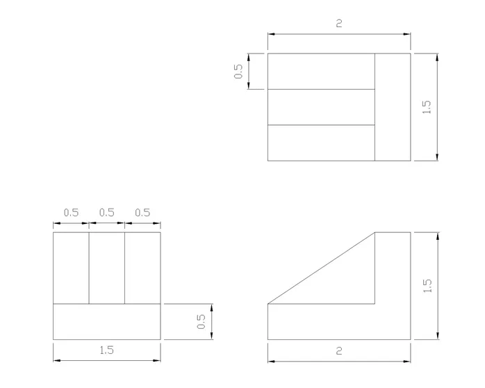
Drawing of diagram with 3 vertical rectangles
- Command: RECTANG
- Specify first corner point or [Chamfer/Elevation/Fillet/Thickness/Width]: 0,0
- Specify other corner point or [Area/Dimensions/Rotation]: d
- Specify length for rectangles <10>: 1.5
- Specify width for rectangles <10>: 0.5
- Specify other corner point or [Area/Dimensions/Rotation]:
- Command:
- RECTANG
- Specify first corner point or [Chamfer/Elevation/Fillet/Thickness/Width]: 0,0.5
- Specify other corner point or [Area/Dimensions/Rotation]: d
- Specify length for rectangles <2>: 0.5
- Specify width for rectangles <1>: 1
- Specify other corner point or [Area/Dimensions/Rotation]:
- Command: COPY
- Select objects: 1 found
- Select objects:
- Current settings: Copy mode = Multiple
- Specify base point or [Displacement/mOde] <Displacement>: d
- Specify displacement <0, 0, 0>: 0.5
- Command:
- COPY
- Select objects: 1 found
- Select objects:
- Current settings: Copy mode = Multiple
- Specify base point or [Displacement/mOde] <Displacement>: d
- Specify displacement <1, 0, 0>: 0.5
Drawing of 2nd diagram with triangular shape
- Command: L
- LINE
- Specify first point: 3,0
- Specify next point or [Undo]: 5,0
- Specify next point or [Undo]: @0,1.5
- Specify next point or [Close/Undo]: @-0.5,0
- Specify next point or [Close/Undo]: @0,-1
- Specify next point or [Close/Undo]: @-1.5,0
- Specify next point or [Close/Undo]: c
- Command: L
- LINE
- Specify first point: 3,0.5
- Specify next point or [Undo]: @1.5,1
- Specify next point or [Undo]:
Drawing of 3rd diagram with 3 horizontal rectangles
- Command: RECTANG
- Specify first corner point or [Chamfer/Elevation/Fillet/Thickness/Width]: 5,2.5
- Specify other corner point or [Area/Dimensions/Rotation]: d
- Specify length for rectangles <1>: 0.5
- Specify width for rectangles <1>: 1.5
- Specify other corner point or [Area/Dimensions/Rotation]:
- Command:
- RECTANG
- Specify first corner point or [Chamfer/Elevation/Fillet/Thickness/Width]: 4.5,2.5
- Specify other corner point or [Area/Dimensions/Rotation]: d
- Specify length for rectangles <1>: 1.5
- Specify width for rectangles <2>: 0.5
- Command: COPY
- Select objects: 1 found
- Select objects:
- Current settings: Copy mode = Multiple
- Specify base point or [Displacement/mOde] <Displacement>: d
- Specify displacement <0, 0, 0>: <Ortho on> 0.5
- Command:
- COPY
- Select objects: 1 found
- Select objects:
- Current settings: Copy mode = Multiple
- Specify base point or [Displacement/mOde] <Displacement>: d
- Specify displacement <0, 1, 0>: 0.5
Results:
Drawing No 7
Aim: Drawing of Given Drawing using various tools in AutoCAD
Procedure:
Starting from the first point as the origin of UCS i.e. (0,0)
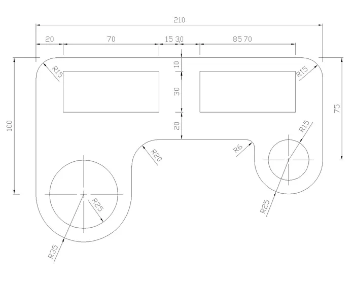
Drawing of a polygon with dimensions as 100, 210, 75, 50, 90, 40, 70
- Command: L
- LINE
- Specify first point: 0,0
- Specify next point or [Undo]: @0,100
- Specify next point or [Undo]: @210,0
- Specify next point or [Close/Undo]: @0,-75
- Specify next point or [Close/Undo]: @-50,0
- Specify next point or [Close/Undo]: @0,15
- Specify next point or [Close/Undo]: @-90,0
- Specify next point or [Close/Undo]: @0,-40
- Specify next point or [Close/Undo]: c
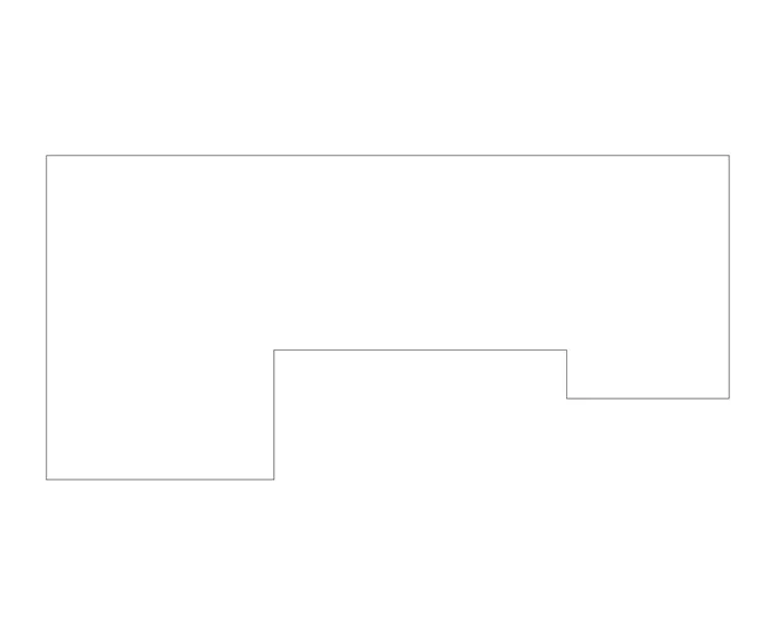
Applying fillet operations on the above polygon
- Command: FILLET
- Current settings: Mode = TRIM, Radius = 0
- Select first object or [Undo/Polyline/Radius/Trim/Multiple]: r
- Specify fillet radius <0>: 35
- Select first object or [Undo/Polyline/Radius/Trim/Multiple]:
- Select second object or shift-select to apply corner or [Radius]:
- Command:
- FILLET
- Current settings: Mode = TRIM, Radius = 35
- Select first object or [Undo/Polyline/Radius/Trim/Multiple]: r
- Specify fillet radius <35>: 25
- Select first object or [Undo/Polyline/Radius/Trim/Multiple]:
- Select first object or [Undo/Polyline/Radius/Trim/Multiple]:
- Select second object or shift-select to apply corner or [Radius]:
- Command:
- FILLET
- Current settings: Mode = TRIM, Radius = 25
- Select first object or [Undo/Polyline/Radius/Trim/Multiple]: r
- Specify fillet radius <25>: 15
- Select first object or [Undo/Polyline/Radius/Trim/Multiple]:
- Select second object or shift-select to apply corner or [Radius]:
- Command:
- FILLET
- Current settings: Mode = TRIM, Radius = 15
- Select first object or [Undo/Polyline/Radius/Trim/Multiple]: r
- Specify fillet radius <15>: 15
- Select first object or [Undo/Polyline/Radius/Trim/Multiple]:
- Select second object or shift-select to apply corner or [Radius]:
- Command:
- FILLET
- Current settings: Mode = TRIM, Radius = 15
- Select first object or [Undo/Polyline/Radius/Trim/Multiple]: r
- Specify fillet radius <15>: 20
- Select first object or [Undo/Polyline/Radius/Trim/Multiple]:
- Select second object or shift-select to apply corner or [Radius]:
- Command:
- FILLET
- Current settings: Mode = TRIM, Radius = 20
- Select first object or [Undo/Polyline/Radius/Trim/Multiple]: r
- Specify fillet radius <20>: 6
- Select first object or [Undo/Polyline/Radius/Trim/Multiple]:
- Select second object or shift-select to apply corner or [Radius]:
- Command: ERASE
- Select objects: 1 found
- Select objects: 1 found, 2 total
- Select objects:
Drawing of circles and rectangles
- Command: RECTANG
- Specify first corner point or [Chamfer/Elevation/Fillet/Thickness/Width]: 20,60
- Specify other corner point or [Area/Dimensions/Rotation]: d
- Specify length for rectangles <2>: 70
- Specify width for rectangles <1>: 30
- Specify other corner point or [Area/Dimensions/Rotation]:
- Command: COPY
- Select objects: 1 found
- Select objects:
- Current settings: Copy mode = Multiple
- Specify base point or [Displacement/mOde] <Displacement>: d
- Specify displacement <0, 1, 0>: <Ortho on> 100
- Command: CIRCLE
- Specify center point for circle or [3P/2P/Ttr (tan tan radius)]: 35,0
- Specify radius of circle or [Diameter] <2>: d
- Specify diameter of circle <3>: 50
- Command:
- CIRCLE
- Specify center point for circle or [3P/2P/Ttr (tan tan radius)]: 185,25
- Specify radius of circle or [Diameter] <25>: d
- Specify diameter of circle <50>: 30
- Command: CENTERMARK
- Select circle or arc to add center mark:
- Select circle or arc to add center mark:
- Select circle or arc to add center mark:
Results:
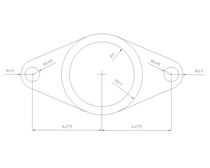
Drawing No 8
Aim: Drawing of Given Drawing using various tools in AutoCAD
Procedure:
Starting from the first point as the origin of UCS i.e. (0,0)
Drawing of circles
- Command: CIRCLE
- Specify center point for circle or [3P/2P/Ttr (tan tan radius)]: 0,0
- Specify radius of circle or [Diameter] <15>: d
- Specify diameter of circle <30>: 4
- Command:
- CIRCLE
- Specify center point for circle or [3P/2P/Ttr (tan tan radius)]: 0,0
- Specify radius of circle or [Diameter] <2>: d
- Specify diameter of circle <4>: 5
- Command:
- CIRCLE
- Specify center point for circle or [3P/2P/Ttr (tan tan radius)]: -4.275,0
- Specify radius of circle or [Diameter] <3>: d
- Specify diameter of circle <5>: 0.9
- Command: MIRROR
- Select objects: Specify opposite corner: 1 found
- Select objects:
- Specify first point of mirror line:
- Specify second point of mirror line: <Ortho on>
- Erase source objects? [Yes/No] <No>: n
- Command: L
- LINE
- Specify first point: -4.275,0.9
- Specify next point or [Undo]: <Ortho off>
- Specify next point or [Undo]:
- Command:
- LINE
- Specify first point: 4.275,0.9
- Specify next point or [Undo]:
- Specify next point or [Undo]:
- Command: MIRROR
- Select objects: 1 found
- Select objects: 1 found, 2 total
- Select objects:
- Specify first point of mirror line:
- Specify second point of mirror line: <Ortho on>
- Erase source objects? [Yes/No] <No>: n
- Command: FILLET
- Current settings: Mode = TRIM, Radius = 6
- Select first object or [Undo/Polyline/Radius/Trim/Multiple]: r
- Specify fillet radius <6>: 0.9
- Select first object or [Undo/Polyline/Radius/Trim/Multiple]:
- Select second object or shift-select to apply corner or [Radius]:
- Command:
- FILLET
- Current settings: Mode = TRIM, Radius = 1
- Select first object or [Undo/Polyline/Radius/Trim/Multiple]: r
- Specify fillet radius <1>: 0.9
- Select first object or [Undo/Polyline/Radius/Trim/Multiple]:
- Select second object or shift-select to apply corner or [Radius]:
- Command:
- FILLET
- Current settings: Mode = TRIM, Radius = 1
- Command: CENTERMARK
- Select circle or arc to add center mark:
- Select circle or arc to add center mark:
- Select circle or arc to add center mark:
Results:
Drawing No 9
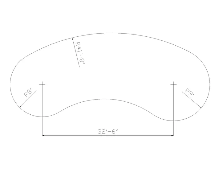
Aim: Drawing of Given Drawing using various tools in AutoCAD
Procedure:
Starting from the first point as the origin of UCS i.e. (0,0)
Creating 2 points 32’6” distance away
- Command: PO
- POINT
- Current point modes: PDMODE=0 PDSIZE=0'-0"
- Specify a point: 0,0
- Command:
- POINT
- Current point modes: PDMODE=0 PDSIZE=0'-0"
- Specify a point: 32'6",0
- Command: PTYPE
- Regenerating model.
- Regenerating model.
- Command: CIRCLE
- Specify center point for circle or [3P/2P/Ttr (tan tan radius)]: 0,0
- Specify radius of circle or [Diameter] <0'-1">: 8'
- Command:
- CIRCLE
- Specify center point for circle or [3P/2P/Ttr (tan tan radius)]: 32'6",0
- Specify radius of circle or [Diameter] <8'-0">: 9'
- Command: C
- CIRCLE
- Specify center point for circle or [3P/2P/Ttr (tan tan radius)]: t
- Specify point on object for first tangent of circle:
- Specify point on object for second tangent of circle:
- Specify radius of circle <9'-0">: 41'8"
- Command: C
- CIRCLE
- Specify center point for circle or [3P/2P/Ttr (tan tan radius)]: t
- Specify point on object for first tangent of circle:
- Specify point on object for second tangent of circle:
- Specify radius of circle <41'-8">: 20'10"
Trimming excess arcs from the diagram
- Command: tr
- TRIM
- Current settings: Projection=UCS, Edge=None, Mode=Quick
- Select object to trim or shift-select to extend or
- [cuTting edges/Crossing/mOde/Project/eRase]:
- Select object to trim or shift-select to extend or
- [cuTting edges/Crossing/mOde/Project/eRase/Undo]:
- Select object to trim or shift-select to extend or
- [cuTting edges/Crossing/mOde/Project/eRase/Undo]:
- Select object to trim or shift-select to extend or
- [cuTting edges/Crossing/mOde/Project/eRase/Undo]:
- Select object to trim or shift-select to extend or
- [cuTting edges/Crossing/mOde/Project/eRase/Undo]:
Results:
Drawing No 10
Aim: Drawing of Given Drawing using various tools in AutoCAD
Procedure:
Starting from the first point as the origin of UCS i.e. (0,0). The assumed dimension of the square is 10’ due to the absence of depicted dimensions in question.
- Command: REC
- RECTANG
- Specify first corner point or [Chamfer/Elevation/Fillet/Thickness/Width]: 0,0
- Specify other corner point or [Area/Dimensions/Rotation]: d
- Specify length for rectangles <10'-0">: 10'
- Specify width for rectangles <10'-0">: 10'
- Specify other corner point or [Area/Dimensions/Rotation]:
- Command: SCALE
- Select objects: 1 found
- Select objects:
- Specify base point:
- Specify scale factor or [Copy/Reference]: c
- Scaling a copy of the selected objects.
- Specify scale factor or [Copy/Reference]: 0.9
- Command: RO
- ROTATE
- Current positive angle in UCS: ANGDIR=counterclockwise ANGBASE=0
- Select objects: Specify opposite corner: 2 found
- Select objects:
- Specify base point:
- Specify rotation angle or [Copy/Reference] <0>: c
- Rotating a copy of the selected objects.
- Specify rotation angle or [Copy/Reference] <0>: 45
- Command: TR
- TRIM
- Current settings: Projection=UCS, Edge=None, Mode=Quick
- Select object to trim or shift-select to extend or
- [cuTting edges/Crossing/mOde/Project/eRase]:
- Select object to trim or shift-select to extend or
- [cuTting edges/Crossing/mOde/Project/eRase/Undo]:
- Specify next fence point or [Undo]:
- Specify next fence point or [Undo]:
- Specify next fence point or [Undo]:
- Specify next fence point or [Undo]:
- Select object to trim or shift-select to extend or
- [cuTting edges/Crossing/mOde/Project/eRase/Undo]:
- Select object to trim or shift-select to extend or
- [cuTting edges/Crossing/mOde/Project/eRase/Undo]:
- Specify next fence point or [Undo]:
- Specify next fence point or [Undo]:
- Specify next fence point or [Undo]:
- Specify next fence point or [Undo]:
- Select object to trim or shift-select to extend or
- [cuTting edges/Crossing/mOde/Project/eRase/Undo]:
- Select object to trim or shift-select to extend or
- [cuTting edges/Crossing/mOde/Project/eRase/Undo]:
- Specify next fence point or [Undo]:
- Specify next fence point or [Undo]:
- Specify next fence point or [Undo]:
- Specify next fence point or [Undo]:
- Select object to trim or shift-select to extend or
- [cuTting edges/Crossing/mOde/Project/eRase/Undo]:
- Select object to trim or shift-select to extend or
- [cuTting edges/Crossing/mOde/Project/eRase/Undo]:
- Specify next fence point or [Undo]:
- Specify next fence point or [Undo]:
- Specify next fence point or [Undo]:
- Specify next fence point or [Undo]:
- Select object to trim or shift-select to extend or
- [cuTting edges/Crossing/mOde/Project/eRase/Undo]:
- Command: TR
- TRIM
- Current settings: Projection=UCS, Edge=None, Mode=Quick
- Select object to trim or shift-select to extend or
- [cuTting edges/Crossing/mOde/Project/eRase]:
- Select object to trim or shift-select to extend or
- [cuTting edges/Crossing/mOde/Project/eRase/Undo]:
- Specify next fence point or [Undo]:
- Specify next fence point or [Undo]:
- Specify next fence point or [Undo]:
- Specify next fence point or [Undo]:
- Select object to trim or shift-select to extend or
- [cuTting edges/Crossing/mOde/Project/eRase/Undo]:
- Select object to trim or shift-select to extend or
- [cuTting edges/Crossing/mOde/Project/eRase/Undo]:
- Specify next fence point or [Undo]:
- Specify next fence point or [Undo]:
- Specify next fence point or [Undo]:
- Specify next fence point or [Undo]:
- Select object to trim or shift-select to extend or
- [cuTting edges/Crossing/mOde/Project/eRase/Undo]:
- Select object to trim or shift-select to extend or
- [cuTting edges/Crossing/mOde/Project/eRase/Undo]:
- Specify next fence point or [Undo]:
- Specify next fence point or [Undo]:
- Specify next fence point or [Undo]:
- Specify next fence point or [Undo]:
- Select object to trim or shift-select to extend or
- [cuTting edges/Crossing/mOde/Project/eRase/Undo]:
- Select object to trim or shift-select to extend or
- [cuTting edges/Crossing/mOde/Project/eRase/Undo]:
- Specify next fence point or [Undo]:
- Specify next fence point or [Undo]:
- Specify next fence point or [Undo]:
- Specify next fence point or [Undo]:
- Select object to trim or shift-select to extend or
Results:

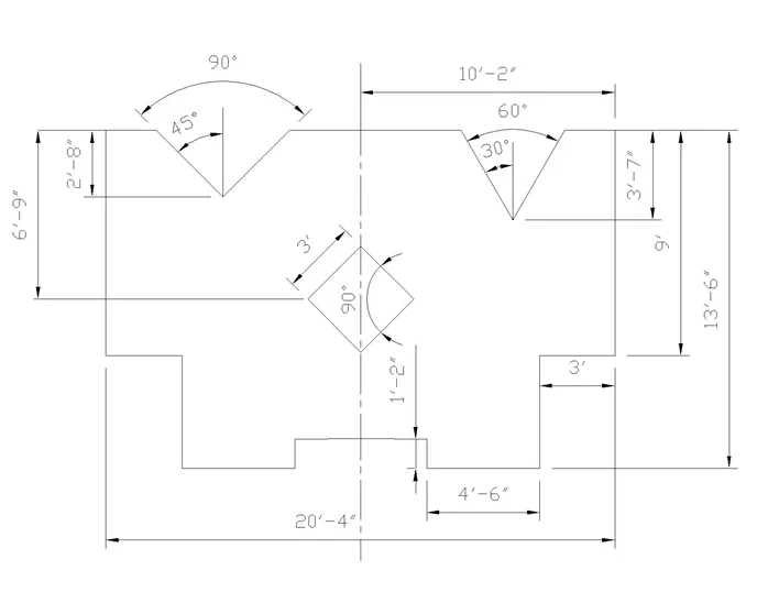
Drawing No 11
Aim: Drawing of Given Drawing using various tools in AutoCAD
Procedure:
Starting from first point as origin of UCS i.e. (0,0)
- Command: L
- LINE
- Specify first point: 0,0
- Specify next point or [Undo]: @0,9'
- Specify next point or [Undo]: @2',0
- Specify next point or [Close/Undo]: @2'8",
- Point or option keyword required.
- Specify next point or [Close/Undo]: @2'8",-2'8"
- Specify next point or [Close/Undo]: @2'8",2'8"
- Specify next point or [Close/Undo]:
- Specify next point or [Close/Undo]: 10'2",9'
- Specify next point or [Close/Undo]: @4',0
- Specify next point or [Close/Undo]: @2'0.826",-3'7"
- Specify next point or [Undo]: @2'0.826",3'7"
- Specify next point or [Undo]: @2',0
- Specify next point or [Close/Undo]:
- Specify next point or [Undo]: @0,-9'
- Specify next point or [Undo]: @-3',0
- Specify next point or [Close/Undo]: @0,-4'6"
- Specify next point or [Close/Undo]:
- Specify next point or [Close/Undo]: @-4'6",0
- Specify next point or [Close/Undo]: @0,1'2"
- Specify next point or [Close/Undo]:
Drawing Line to divide polygon equally
- Command: _line
- Specify first point:
- Specify next point or [Undo]:
- Specify next point or [Undo]:
Bottom Part of Polygon seems symmetrical
- Command:
- Command: MIRROR
- Specify first point of mirror line:
- Specify second point of mirror line:
- Erase source objects? [Yes/No] <No>:
Draw square in the middle of polygon
- RECTANG
- Specify first corner point or [Chamfer/Elevation/Fillet/Thickness/Width]:
- Specify other corner point or [Area/Dimensions/Rotation]: d
- Specify length for rectangles <10'-0">: 3'
- Specify width for rectangles <10'-0">: 3'
- Command: RO
- ROTATE
- Current positive angle in UCS: ANGDIR=counterclockwise ANGBASE=0
- Select objects: 1 found
- Select objects:
- Specify base point:
- Specify rotation angle or [Copy/Reference] <45>: c
- Rotating a copy of the selected objects.
- Specify rotation angle or [Copy/Reference] <45>: 45
Results:
Conclusion:
All the above drawings have been drawn using various tools of AutoCAD like – line, point, rectangle, circle, fillet, copy, move, scale, chamfer, dimension linear, dimension angular, dimension radius, dimension aligned, centermark, and various others. Extensive use of various commands of AutoCAD gives a well-founded practice and confidence. These drawing of basic line diagrams gives foundation for advanced study.