Simulink Week one challenge
Task 1
Aim :
To plot a basic function `y(x)=(x-1)*(x-3)^2 *(x-9)^2`using basic simulink blocks
Ojective :
To create a plot for the above function using simulink and show the results.
Theory:
Simulink:
Simulink is a Matlab-based graphical programming environment for modeling, simulating and analyzing multidomain dynamical system. Its primary interface is a graphical block diagramming tool and a customizable set of block libraries. It offers tight integration with the rest of the Matlab environment and can either drive MATLAB or be scripted from it. Simulink is widely used in automatic control and digital signal processing tool for multidomain simulation and model-based design.
Simulink model of the function:
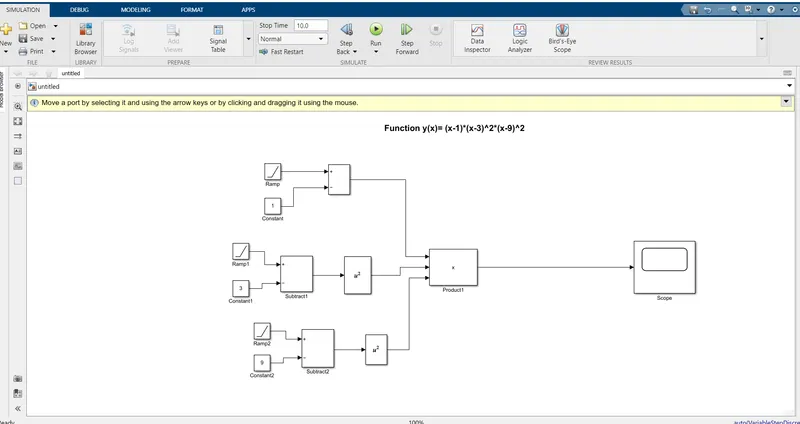
Explanation :
- We have defined variable x using ramp block(value changes with time).
- Used constant block to define constant values(1,3,9).
- Used Subtract block to subtract variables from constant.
- Used Square block to square when needed.
- Used Product block to mutiply the three values.
- Finally used Scope block to plot the results.
Output :
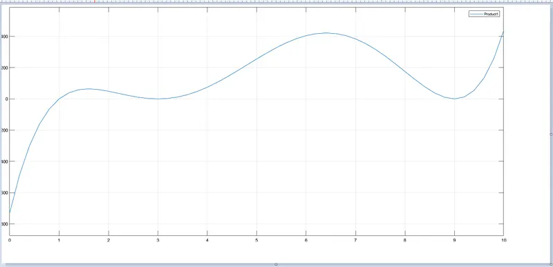
Plot for the function `y(x)=(x-1)*(x-3)^2 *(x-9)^2`has been inserted
Observations:
We can see how the function y(x) responds for different values of x.
We can see how the curves goes for the function.
Conclusion:
The plotting of the function `y(x)=(x-1)*(x-3)^2 *(x-9)^2` is done using simulink and the plot is obtained.
Task 2
Aim : To run 'Suspension system comparision' using simulink.
Ojective :
- What is the objective of the simulation? What are the similarities and differences between the three systems understudy?
- What are your observations from the results?
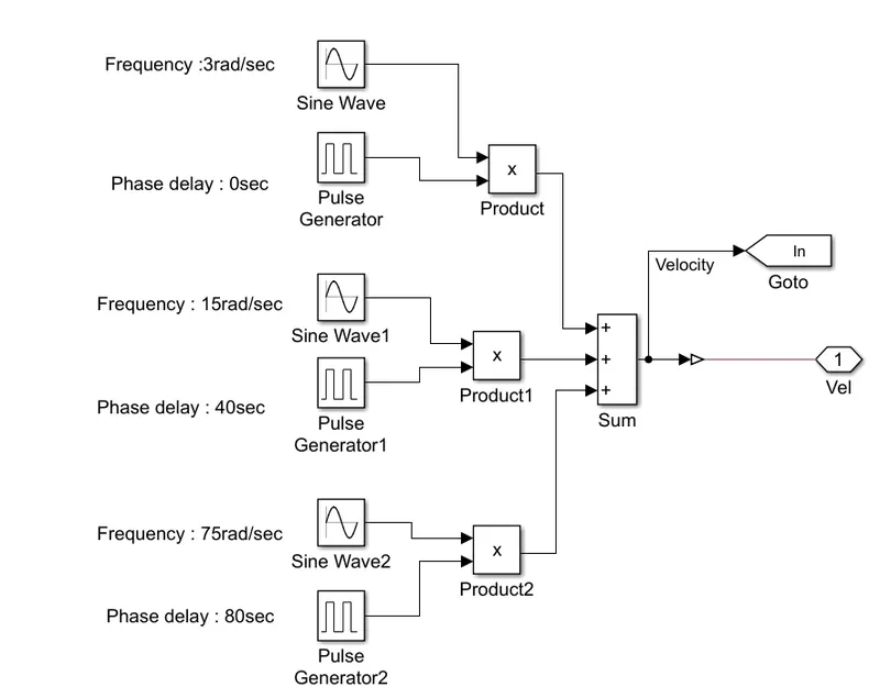
- How the oscillating velocity source is created?
Theory :
Shock Absorber : Shock absorbers are an integral part of a vehicle's suspension. A shock absorber is designed to absorb or dampen the compression and rebound of the springs and suspension. They control the unwanted and excess spring motion. Shock absorbers keep your tires in contact with the road at all times.
The proper name for shock absorbers is “damper” as it serves to dampen motion. While shock is absorbed by the spring, the damper functions to modulate the oscillations (bouncing). The unique feature of a damper is that its resistance to motion is proportional to how fast the motion occurs.
Simulink model of the Suspension system comparision :
Output :
The output plot of 'Suspension system comparision' is shown below,
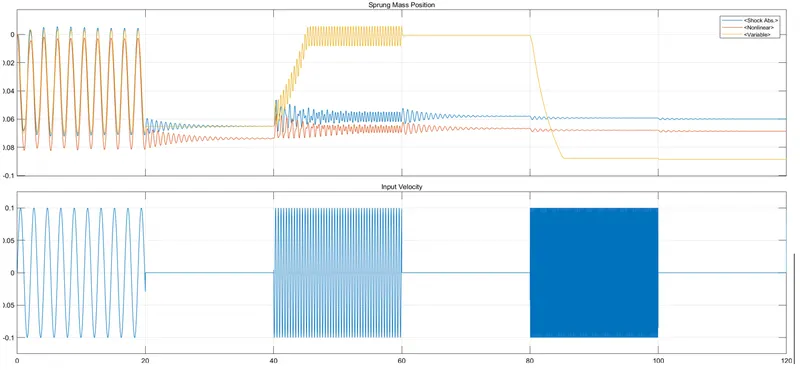
1. Sprung Mass Position,
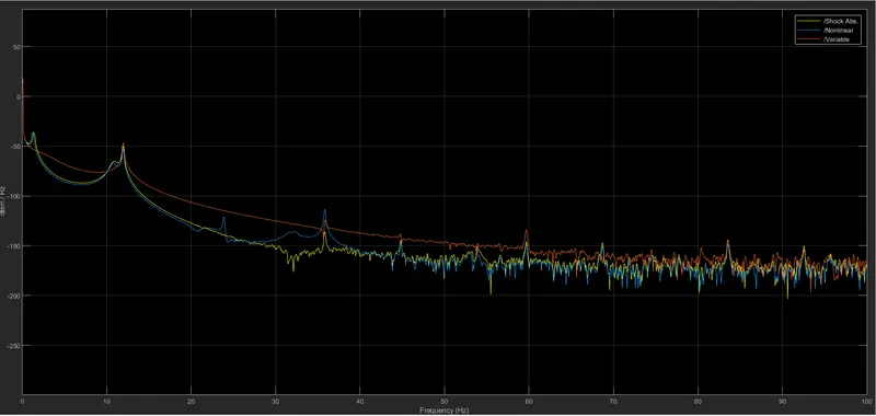
2. Spectrum Analyzer :
1.Objective of the simulation :
The objective of the above simulation is To test three different shock absorber system under Oscillating velocity source and plot the results.
Similarities and differences between the three systems Understudy :
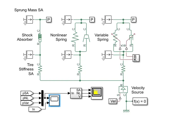
- This example shows a testbed containing three sets of springs and dampers excited by the same oscillating velocity source.
- The first uses the Shock Absorber block and includes linear stiffness and damping. Optional friction and hard stops are not used.
- The second shock absorber uses a Nonlinear Translational Spring and a Nonlinear Translational Damper specified by symmetric polynomials.
- The third uses a Variable Translational Spring and Variable Translational Damper.
- The spring constant is varied during the simulation using open loop control and the damping coefficient adjusts to ensure critical damping is achieved. Closed loop control can be added to simulate an adaptive suspension system.
- Tire stiffness, sprung mass and unsprung mass are similar for all three system.
- Goto blocks are send signals to From blocks that have the specified tag.
2.Observation from the result :
1. Here from the graph, we applied input oscillating frequency of 3 rad/sec for a period of 0-20 sec,in all three system the position of the sprung mass is almost similar.
2. And from 20 - 40 sec we give no input velocity then the variable spring mass position is also contant and the shock absorber and non linear show similar movement.
3. And then we increase the input oscillating frequency to 15rad/sec for a time period between 40-60 sec, the variable shows a positive sprung mass postion and and maintains its position and the non linear and shock absorber show similar movement with some variation in sprung mass polsition.
4. And then from 60-80 sec, when input velocity is zero the variable also show zero sprung mass position and the non linear and shock absorber initially gives more movement and the comes to a constant position.
5. And then from 80-100sec we increase the input oscillating frequency tp 75rad/sec, the variable shows a neagtive sprung mass position and then moves in a constant positon and the non linear and the shock absorber shows a similar movement of the sprung position.
6. In the spectrum analyzer, the variable consumes more power when compared to the non linear and the shock absorber.
3.Oscillating velocity source :
Ideal translation velocity source :
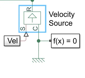
The block represents an ideal source of velocity that generates a velocity differential at its terminals proportional to the input physical signal. The source is ideal in a sense that it is assumed to be powerful enough to maintain specified velocity regardless of the force exerted on the system.
Block connections R and C are mechanical translational conserving ports. Port S is a physical signal port, through which control signal that drives the source is applied. The relative velocity is determined as V = V_R - V_C, where V_R and V_C are the absolute velocities of terminals R and C, respectively.
If we press the Vel block this opens,
Conclusion :
- Simulink example Suspension System Comparision is Done in Simulink sucessfully.
- When comparing all system, the shock absorber spring system has good stiffness and vibrations are less.
- The non-linear spring system is same as the shock absorber but the stiffness is low comparatively.
- The variable spring system has the very low stifness with sudden highs and fall and overall shows a poor performance.